
Master AC drive troubleshooting with structured diagnostics, fault isolation, and controlled restarts to minimize costly industrial downtime.
A tripped AC drive can look like a small electrical fault, but the operational consequences are much larger. One industrial survey found that 83% of decision makers said unplanned downtime costs at least $10,000 per hour, while 76% said the cost can reach $500,000 per hour. The same survey reported equipment-related interruptions at least monthly for 44% of respondents and every week for 14%. These figures are reported in ABB's industrial downtime survey.
That cost structure changes how maintenance teams should approach a drive trip. A reset might restore production temporarily, but it doesn't prove the drive caused the problem. The fault may be in the incoming supply, motor, output cable, grounding, cooling, control logic, fieldbus, or the process itself. Effective AC drive troubleshooting isolates those possibilities in a controlled order, preserves the evidence, and authorizes a restart only when the original failure path has been addressed.
Table of Contents
- The True Cost of Unplanned Drive Downtime
- Safety Protocols and Initial Fault Isolation
- Electrical Testing and Component Verification
- Tracing External System and Process Interactions
- Managing Environmental Degradation and Aging
- Executing Controlled Restarts and Post-Trip Monitoring
The True Cost of Unplanned Drive Downtime
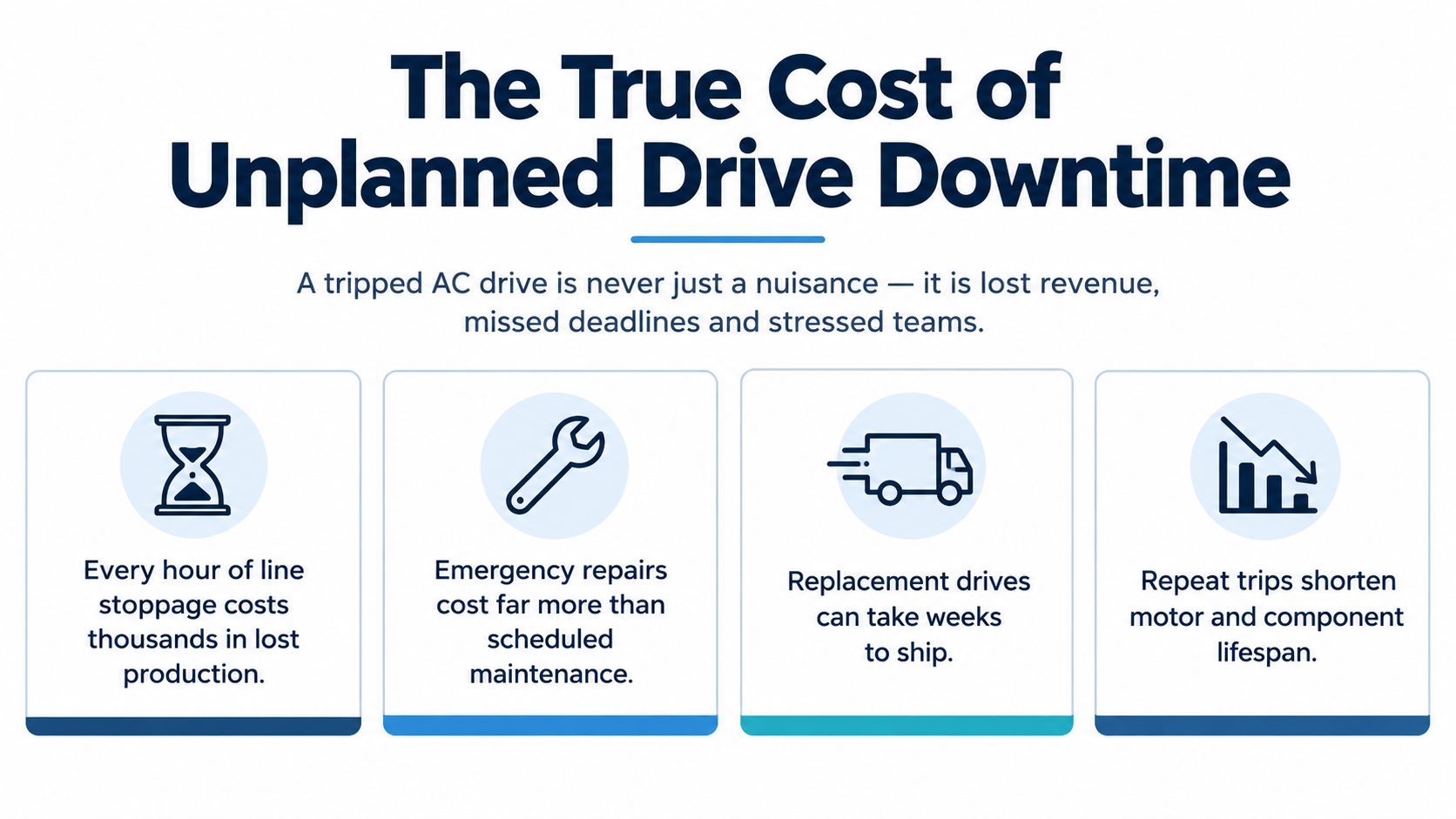
A drive trip is an operational event, not merely an equipment alarm. The motor stops, the process falls out of sequence, upstream and downstream equipment may continue operating in an abnormal state, and operators often face pressure to restore the line before the cause is understood. That pressure is where poor decisions begin.
The familiar response is to acknowledge the alarm, reset the drive, and see whether it runs. If it trips again, someone may replace a fuse, a control board, or the entire drive without confirming the failure path. This approach can produce a short-term recovery while leaving a grounded motor, restricted cooling path, unstable supply, or excessive mechanical load ready to cause another trip.
Why first-pass diagnosis matters
The value of a structured first response is easy to underestimate. The technician who records the fault history before clearing it may identify an overtemperature pattern that points to airflow restriction. The technician who checks the motor and cable before condemning the inverter may find insulation damage that would destroy a replacement unit. The engineer who compares the alarm timestamp with a process change may discover that the drive is correctly protecting the machine from a new load condition.
A survey of installed variable frequency drives reported that only 33% were free of problems, while 20% required replacement parts and 47% had problems that didn't require parts, as summarized in this VFD troubleshooting reference. The practical lesson is important. A fault indication doesn't automatically mean the drive needs to be replaced. Many incidents are recoverable through cleaning, tightening, thermal inspection, parameter review, insulation testing, or correction of an external condition.
Practical rule: Don't approve a replacement because the drive tripped. Approve it when the evidence shows that the drive's internal power or control section has failed, or when its condition and lifecycle risk make repair uneconomical.
The cost of the wrong recovery
Trial-and-error replacement has three disadvantages. First, it consumes time while technicians wait for parts or repeat tests. Second, it can damage the replacement if the original external fault remains. Third, it destroys an opportunity to learn from the event because the original fault history, operating conditions, and physical evidence may be lost.
Maintenance teams should therefore treat the first response as a diagnostic containment process. Secure the equipment, capture the drive's memory, establish whether the fault is repeatable, separate the drive from the motor and supply where safe, and test each part of the system independently. That discipline protects production, personnel, and the next drive that will be connected to the same process.
Safety Protocols and Initial Fault Isolation
Safety starts before the cabinet door opens. A drive can retain hazardous energy after incoming power has been removed, and a control circuit or remote command can create an unexpected start condition. The person performing the work must follow the site's electrical safety rules, manufacturer instructions, and approved lockout/tagout procedure.
Capture evidence before clearing the alarm
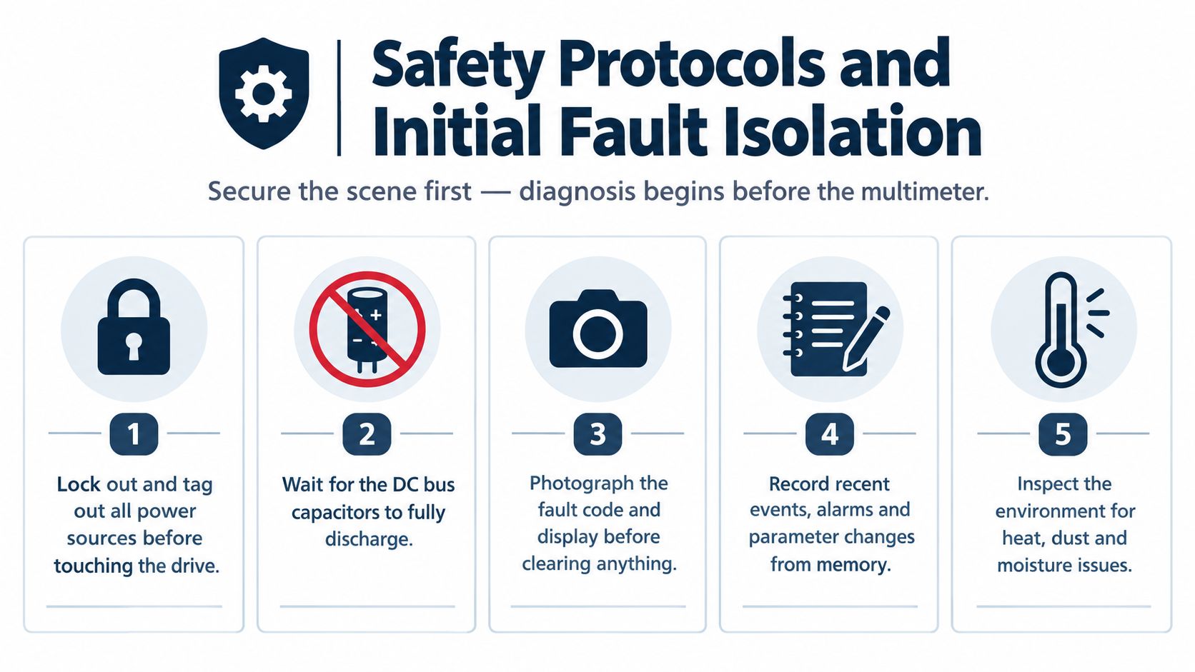
Photograph the display and record the exact alarm code, not a general description such as “overcurrent.” Note whether the trip occurred during acceleration, deceleration, steady running, startup, braking, or a process transition. Record the commanded speed, output frequency, current, load condition, motor temperature, cabinet temperature, and any unusual sound or smell reported by operators.
Before clearing anything, extract the event history and parameter changes from the drive. Modern drives commonly retain the last 10 to 20 faults with timestamps and operating conditions, making that memory one of the most valuable diagnostic records, as described in this technical fault-history guide. Preserve the information in the maintenance record, especially if the fault is intermittent.
A useful intake record includes:
- Alarm details: Exact code, subcode, timestamp, and whether the alarm was a trip, warning, or inhibit.
- Operating state: Speed reference, output frequency, motor current, direction, and process step.
- Recent changes: New motor, cable work, parameter edits, PLC logic, fieldbus equipment, mechanical work, or cabinet modifications.
- Physical evidence: Dust, oil mist, moisture, discoloration, loose conductors, blocked filters, fan condition, and signs of overheating.
Establish a safe testing boundary
Apply lockout/tagout to every relevant energy source. That may include the drive's incoming supply, bypass supply, control power, auxiliary circuits, remote start circuits, and stored mechanical energy in the driven equipment. Test for the absence of voltage with an approved meter, using the site's verification method and a known live source before and after the test where required by procedure.
Wait for the drive's specified discharge period, then verify the DC bus directly with a properly rated instrument. A display going dark doesn't prove that the capacitors are discharged. Don't touch the DC bus, power terminals, or internal components until the measured voltage is at the safe level required by the manufacturer's instructions and site rules.
Once isolated, define the boundary for testing. Disconnect the motor leads when the manufacturer permits it and when doing so won't create another hazard. Keep control wiring identified, protect exposed terminals, and prevent remote systems from re-energizing the equipment. The objective isn't to make the cabinet safe. It's to create a known state in which supply-side, drive-side, and motor-side tests can be interpreted correctly.
Electrical Testing and Component Verification
With the equipment isolated and the fault record preserved, test from the source toward the load. That sequence prevents assumptions from spreading through the diagnosis. A drive that reports an overcurrent or ground fault may be reacting correctly to a downstream defect, while an undervoltage alarm may originate at the supply rather than inside the converter.
Test the incoming power first
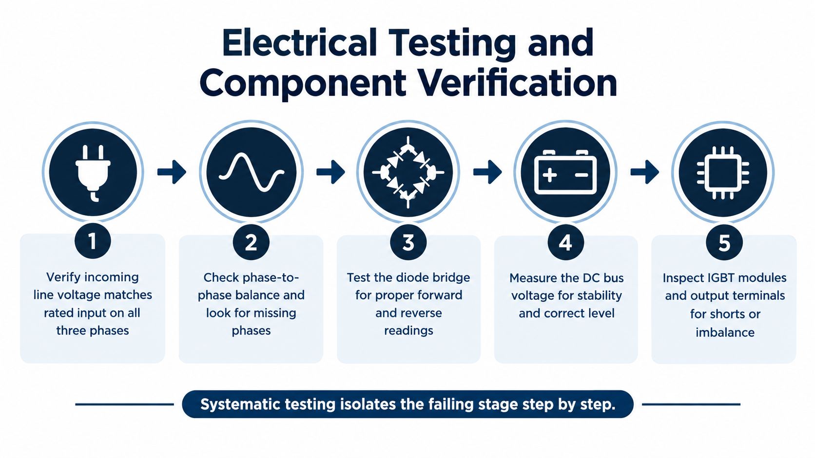
Measure line-to-line voltage at the drive input on all three phases. The reading should remain within approximately ±10% of nominal, and phase imbalance should remain below 3%, based on the workflow described in this AC drive testing guide. Take readings under conditions that reproduce the fault where possible. A supply that looks acceptable at no load can sag or distort when another large load starts.
Check for a missing phase, loose termination, damaged fuse holder, overheated disconnect, or contactor pole with excessive resistance. Inspect the terminals for discoloration and torque concerns, but don't retorque energized equipment. A poor connection can create heat and voltage instability without producing an obvious open circuit during a quick meter check.
The rectifier and DC bus require careful interpretation. After isolation and discharge verification, compare diode readings across the input bridge using the manufacturer's test procedure. Abnormal forward or reverse readings, a shorted path, or a significant phase-to-phase difference can indicate damage in the input stage. For the DC bus, verify that the measured value is stable and consistent with the drive's design and supply arrangement. Do not infer a healthy bus solely from a brief startup indication.
Separate the output stage from the motor circuit
Inspect the output terminals, cable lugs, shield terminations, and motor junction box. Look for phase-to-phase shorts, phase-to-ground leakage, damaged insulation, moisture, conductive dust, and cable movement at glands or flex points. A visual inspection doesn't replace electrical testing, but it often explains why a measured defect exists.
Use a properly rated 500 V or 1000 V megohmmeter to test the output cable and motor insulation, following the drive and motor manufacturers' instructions. Test the cable separately from the motor so the results identify the failing section. Readings below 1 megohm at 500 VDC are often treated as evidence of insulation failure in the referenced troubleshooting guidance. That threshold must still be applied with the equipment manufacturer's requirements and the motor's condition in mind.
Never megger through connected drive electronics unless the manufacturer explicitly allows it. Disconnect sensitive components, verify the test configuration, and discharge the tested circuit afterward. A healthy drive connected to a compromised motor can trip immediately, while a damaged output module may show abnormal readings even with the motor and cable removed.
Complete the sequence by checking the IGBT or output power modules according to the drive's service procedure. Look for shorts between terminals, imbalance between phases, cracked solder joints, thermal discoloration, and damage around bus connections. If the input, bus, output, cable, and motor tests are normal but the same fault occurs with the motor isolated, suspicion should move toward the drive's internal power stage or control circuitry.
<iframe width="100%" style="aspect-ratio: 16 / 9;" src="https://www.youtube.com/embed/yEPe7RDtkgo" frameborder="0" allow="autoplay; encrypted-media" allowfullscreen></iframe>Tracing External System and Process Interactions
The drive isn't always the culprit. It may be the component that detects a problem first and shuts down to protect the motor, converter, or process. Treating every trip as an internal drive failure leads to unnecessary parts replacement and guarantees repeat incidents when the external condition remains.
Build the sequence around the event
Start with time correlation. Place the drive fault timestamp beside PLC events, SCADA trends, motor current, speed reference, valve or damper position, pressure, flow, temperature, and operator actions. An intermittent overcurrent that appears only when a valve changes position has a different diagnostic path from an overcurrent that occurs at every acceleration.
Ask what changed before the fault appeared:
- Process conditions: Has the material, viscosity, temperature, recipe, throughput, or operating mode changed?
- Mechanical load: Has a conveyor jammed, a bearing deteriorated, a pump partially blocked, or a fan damper moved?
- Electrical environment: Was nearby high-power equipment added, relocated, or switched differently?
- Control system: Were acceleration, deceleration, current limit, braking, speed reference, or interlock parameters edited?
- Communications: Did a fieldbus timeout, signal distortion, network interruption, or PLC state change occur at the same time?
A fault history that shows rising current before each trip points toward a different cause than a clean current trace followed by a sudden communication loss. The distinction matters because changing the drive won't correct an overloaded machine or a bad reference signal.
Check power quality and control signals
Power-quality distortion can stress the input stage and create protective events that appear unrelated to the supply. Measure voltage and current distortion with a suitable class-A analyzer when the operating environment justifies it. Compare phase currents under the same load and investigate imbalance beyond approximately 3%, as recommended in the field troubleshooting protocol. That source has already been used for the fault-history guidance above, so the operational principle is more important here than repeating the citation.
Review the drive's control mode and command path. A speed reference that jumps, a loss of enable, an incorrect direction command, or a network value that freezes at its last state can create a trip without any failed inverter component. Check the actual command value at the drive, not only the value the PLC believes it transmitted.
Don't overlook grounding and shielding. Poor bonding, damaged shield terminations, and noisy signal routes can produce unstable feedback or communication behavior. For an intermittent fault, capture the drive event, PLC diagnostic state, and process trend together. A single synchronized record is more useful than separate screenshots collected after the event.
Decide whether the drive is reacting correctly
A protective trip is evidence of a condition, not proof of component failure. If the drive reports overload while current rises with mechanical torque, investigate the machine. If it reports a communication fault while power and motor values remain normal, investigate the network and control sequence. If it reports a ground fault with the motor and cable disconnected, internal drive testing becomes more justified.
This system-level approach also supports predictive maintenance. Trend temperature, voltage, current, vibration, load, runtime, and alarm recurrence rather than waiting for a hard trip. The guidance on AI-supported predictive maintenance for industrial drive repair describes this shift from reactive response toward correlated operating data. The value isn't the label attached to the technology. It's the ability to distinguish a developing external condition from a deteriorating internal component before production stops.
Managing Environmental Degradation and Aging
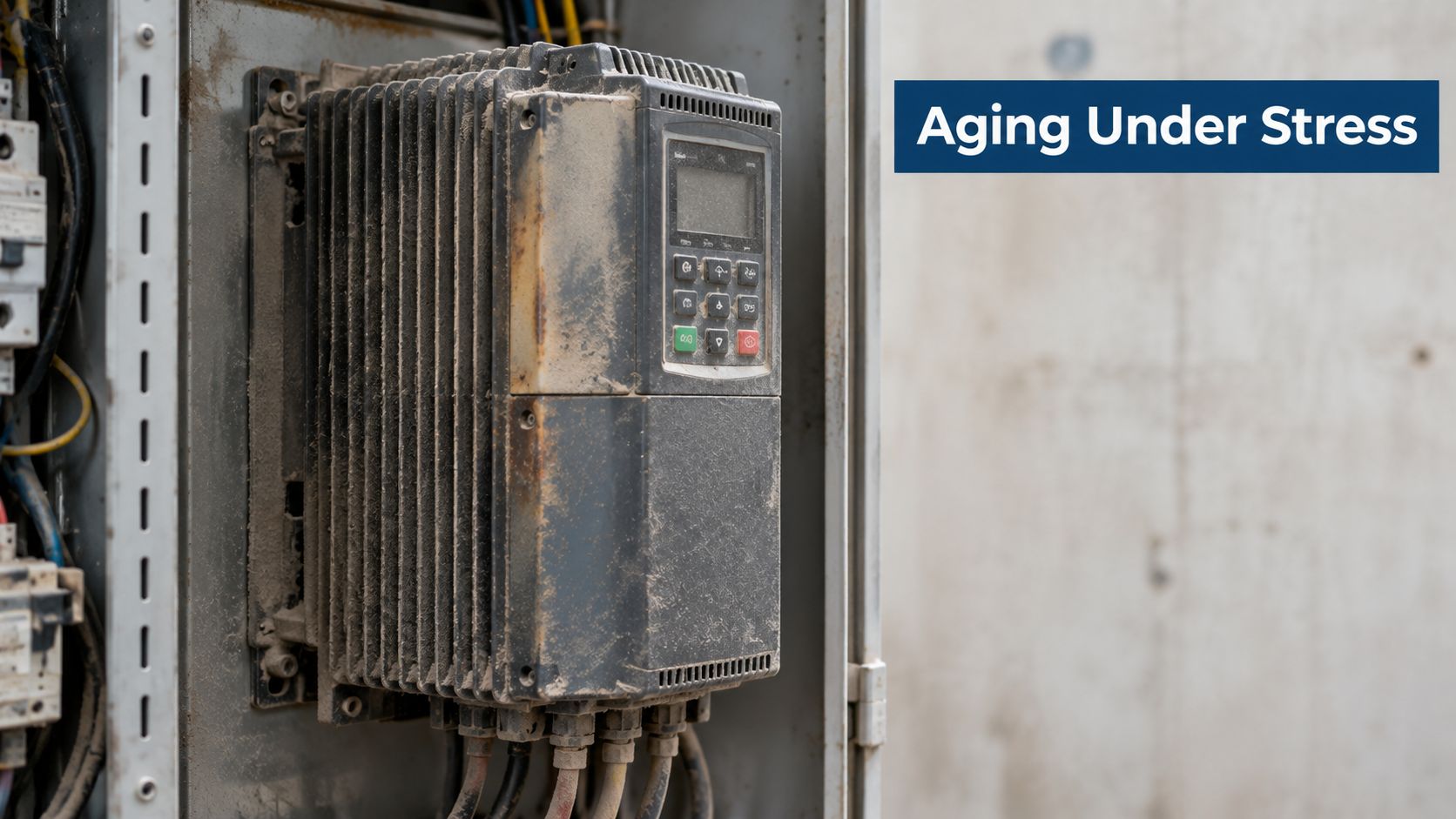
A drive can pass a basic functional test and still be approaching a serious reliability problem. Heat, conductive contamination, moisture, vibration, and repeated electrical stress gradually reduce the margin between normal operation and protective failure. In a harsh cabinet, cleaning and airflow inspection are electrical reliability tasks, not cosmetic work.
Find degradation before the hard trip
Start with the environment around the drive. Check cabinet temperature, fan operation, filters, heat sinks, ventilation paths, door seals, and the presence of oil mist or moisture. Conductive dust can create leakage paths across boards and insulation barriers. Saline atmospheres can accelerate corrosion at terminals, bus connections, connectors, and cooling hardware.
Look for evidence rather than relying on a single temperature reading:
- Thermal evidence: Discoloration, brittle insulation, swollen capacitors, darkened boards, and loose high-current joints.
- Contamination evidence: Deposits on heat sinks, boards, fans, filters, and terminal barriers.
- Mechanical evidence: Vibration marks, cracked supports, loose busbar hardware, and cable strain.
- Trend evidence: Increasing heatsink temperature, current ripple, nuisance alarms, or repeated faults under similar loads.
A drive's expected service life is often about 10 to 15 years under proper conditions, but harsh environments and weak maintenance can shorten that period, as outlined in this variable frequency drive lifecycle guidance. Age alone isn't a replacement decision. Age combined with contamination, thermal history, unsupported components, and recurring alarms is a risk profile.
Choose reconditioning or replacement deliberately
On-site reconditioning makes sense when the drive is physically large, difficult to transport, or still has serviceable major assemblies. It can include controlled cleaning, cooling-system restoration, connection inspection, capacitor assessment, power-module testing, control-board checks, and functional verification under representative conditions. The work should produce documented test results, not just a statement that the unit was cleaned.
Workshop repair may be more appropriate when component-level access, bench testing, or extended load simulation is required. Replacement becomes more defensible when the unit has extensive internal damage, unavailable or unreliable parts, repeated failures after corrective work, or a control architecture that no longer fits the process.
The decision should combine fault history with condition data. A single trip on a clean, stable, well-maintained drive may justify targeted repair. Repeated trips accompanied by rising thermal stress and contamination indicate a broader lifecycle problem that deserves planned intervention.
Turn maintenance into a lifecycle decision
Preventive programs are reported to reduce catastrophic failure rates by 75%, while systematic troubleshooting is reported to reduce mean time to repair by 60% when technicians use repeatable diagnostic workflows, according to the maintenance guidance on VFD troubleshooting. Those figures support a practical maintenance design, but they don't replace site-specific evidence.
Set inspection triggers based on the asset's environment and consequence of failure. Review alarm patterns, thermal readings, current balance, vibration, cooling performance, and cabinet condition during planned shutdowns. For critical medium- and high-voltage equipment, assess whether the work can be completed safely in place before accepting the transport risk and delay of offsite repair.
The correct question isn't “Can this drive run after a reset?” It's “What evidence supports continued operation, what degradation remains, and what intervention prevents the next trip?”
Executing Controlled Restarts and Post-Trip Monitoring
A restart is the final test of the diagnosis, not the beginning of production recovery. Before energizing, confirm that the fault evidence has been saved, the suspected cause has been corrected or contained, and every person involved understands the restart boundary. A reset without those conditions only converts an identified trip into an unverified experiment.
Set release conditions before energizing
Compare the active parameter set with the approved backup. Pay particular attention to motor nameplate data, acceleration and deceleration ramps, current limits, braking settings, control mode, thermal protection, speed limits, and communication configuration. A parameter mismatch can recreate the original symptom even after electrical repairs.
Inspect the power path and motor circuit one more time. Confirm that covers are installed, terminals are secure, guards are in place, cooling paths are clear, and the driven machine can start without exposing personnel to unexpected movement. Verify permissives, interlocks, emergency stops, and remote commands before applying power.
Use a staged restart where the process allows it:
- Energize without a run command and observe initialization, precharge behavior, alarms, and DC bus status.
- Run unloaded or at the lowest practical risk while checking direction, current, output frequency, feedback, and abnormal noise.
- Increase load gradually and compare operating values with the saved baseline or approved commissioning record.
- Return the process to normal duty only after the drive remains stable through the condition that previously caused the trip.
The recommended first steps after a drive trip should be part of the site's restart checklist. The record should show who authorized the restart, what was tested, which parameters were verified, and what restrictions remain.
Monitor the condition, not just the alarm
During the first operating period, watch motor current by phase, output frequency, DC bus behavior, heatsink temperature, cabinet temperature, vibration, process load, and communication status. Compare those values against the actual operating state. A current rise that follows load is expected. A persistent phase imbalance, rising temperature at steady load, or repeated communication error requires investigation.
Keep the original event history intact where the drive permits it, and save a new snapshot after the restart. Correlate any warning with PLC and SCADA records. A drive that runs for a short period and then trips under full load hasn't demonstrated recovery. It has only passed a partial test.
Restart standard: Production should resume because the failure mode is understood and controlled, not because the alarm disappeared.
If the fault returns, stop repeating resets. Reapply the isolation procedure, compare the new event with the original record, and determine whether the condition is identical, progressive, or newly introduced. That comparison often separates an incomplete repair from a second problem in the process or environment.
A sound closeout includes the root cause, evidence collected, corrective action, parameter changes, test results, monitoring period, and preventive action. Update the maintenance strategy while the information is fresh. The purpose of AC drive troubleshooting isn't only to get the motor turning again. It's to prevent the same failure path from taking the line down a second time.
DUCHENG Industrial provides structured on-site diagnosis, controlled restart support, workshop repair, and on-site reconditioning for industrial VFD assets. Visit DUCHENG Industrial to discuss fault isolation, lifecycle maintenance, or a planned recovery for a critical drive.