
Motor starter troubleshooting made practical. Step-by-step diagnosis of contactors, overload relays, and control circuits with safe restoration tips.
The starter fails just as the production line calls for a run. You hear a click, or perhaps a low hum, but the motor never reaches the point where the contactor holds cleanly. Someone resets the overload, another technician checks the motor terminals, and an hour later the team is still working at the wrong end of the circuit.
Motor starter troubleshooting gets faster when you stop treating every failed start as a motor problem. The useful decision is whether the fault is in the control circuit, the contactor and power circuit, or the overload and motor protection path. Each family has different test points, different meter readings, and different repair risks.
A conventional starter remains a straightforward assembly of a control circuit, a switching device, and a power circuit. That basic arrangement has existed through more than a century of starter development. The electric starter motor was patented on August 17, 1915, under U.S. Patent No. 1,150,523, and modern diagnostics still depend on the same fundamental question, does the control signal close the power path reliably under load? The historical and troubleshooting background is documented by Plant Engineering.
Table of Contents
- What Motor Starter Troubleshooting Really Involves
- Pre-Diagnostic Safety and Baseline Checks
- Control Circuit Symptoms and Where to Test First
- Contactor and Power Circuit Faults
- Overload Relay Trips and Current Verification
- Controlled Restart and Post-Fault Verification
- Common Mistakes and a Repeat-Trip Checklist
What Motor Starter Troubleshooting Really Involves
When a starter won't pull in, begin at the point where the symptom occurs. A dead starter, a chattering starter, a contactor that drops out during acceleration, and an overload that trips after several minutes don't point to the same component.
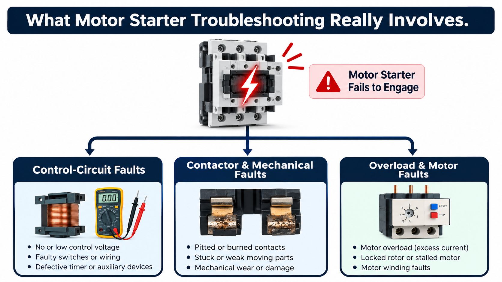
The three fault families
Control-circuit faults live on the command side. Check the control fuse, control transformer, stop and start pushbuttons, door interlocks, auxiliary contacts, overload auxiliary contacts, wiring, and the voltage directly across the contactor coil at A1 and A2. If the coil doesn't receive the expected voltage while the start command is active, don't replace the contactor yet. The fault is upstream.
Contactor and power-circuit faults begin once coil voltage and control continuity are proven. Test line-to-line voltage at the contactor line terminals, then verify that each main pole passes voltage to the load side when the contactor closes. Pitted contacts, a weak coil, a mechanically restricted armature, a missing phase, or a loose power termination can leave the motor without usable power even though the control circuit appears healthy.
Overload faults involve protection settings, current sensing, ambient conditions, and the driven load. A trip doesn't prove the overload relay is defective. It tells you that the relay detected, or believed it detected, a current or thermal condition that requires investigation.
Practical rule: If voltage is correct at A1 and A2 and the coil pulls in decisively, move to the contactor poles. If the poles pass balanced power, move to motor current, overload settings, and the mechanical load.
This guide applies to direct-on-line starters, reversing starters, star-delta arrangements, and soft-starter bypass contactors. Work from the documented schematic, use a true-RMS clamp meter and an insulation tester, and record readings before changing parts. Reliability references list a failure rate of 0.007987 failures per million hours for starters at or below 600 V, with an annualized value of 0.72 failures and a mean time between failures of 1,096,747 hours. For starters above 600 V, the listed failure rate is 0.009071 failures per million hours, with a mean time between failures of 965,683 hours. These figures, compiled from IEEE-based references and tied to IEEE Std 3006.8-2018 Table 2, support planned diagnostic discipline rather than guesswork. See the motor-starter reliability reference.
Pre-Diagnostic Safety and Baseline Checks
Safety starts before the cabinet door opens. Apply lockout/tagout, identify every energy source, verify zero energy with an approved meter, and use the arc-flash PPE required by the site assessment. A conventional starter may not be the only source to isolate, especially where a bypass arrangement, electronic starter, or alternate supply can backfeed the motor circuit.
If the equipment is still operating, capture useful information before isolation. Measure incoming line-to-line voltage, confirm phase rotation, observe the motor's running current, and note any abnormal sound, heat, smell, or vibration. Then isolate the equipment and prove the meter on a known source before and after the absence-of-voltage test.
Establish the electrical baseline
Use a visual inspection before probing terminals. Look for loose lugs, darkened insulation, melted control wire insulation, cracked fuse holders, contamination, and contactor discoloration. With power removed, move the contactor armature by hand where the design permits. It should travel smoothly, return fully, and show no evidence that the contacts are binding or welded.
For a de-energized insulation test, test phase-to-phase and each phase-to-ground at the appropriate isolated circuit points. The acceptable insulation value depends on the motor, cable, temperature, test voltage, and manufacturer or site standard, so don't invent a universal pass value. Compare the result with the equipment's documented baseline and investigate any sharp deterioration.
At the control transformer, record the secondary voltage before and after the fault. Photograph the as-found wiring, mark any heat-discolored terminal, and identify the coil rating from its nameplate. A healthy control circuit should hold its rated voltage under the start command, not merely display a correct open-circuit value.
| Test Point | Healthy Reading | Acceptable Tolerance |
|---|---|---|
| 24 VDC coil, A1 to A2 | Nominal control voltage | ±10% |
| 120 VAC coil, A1 to A2 | Nominal control voltage | 108 to 132 V |
| 240 VAC coil, A1 to A2 | Nominal control voltage | 216 to 264 V |
| Incoming three-phase supply | Balanced line-to-line voltage | Compare all phases with the site baseline |
| Motor terminals | Correct line voltage and phase order | Match nameplate and documented system data |
The commonly used coil benchmark is within ±10% of nominal, including 108 to 132 V for a 120 V AC coil and 216 to 264 V for a 240 V AC coil. The control-coil and overload checking guidance provides these reference values. Don't infer a control fault from a voltage reading taken with the circuit open. Test at A1 and A2 while the start command is active.
Control Circuit Symptoms and Where to Test First
The control circuit should be tested in sequence, not randomly. Start with the symptom, identify whether the coil is being commanded, and then work along the rung until the voltage disappears.
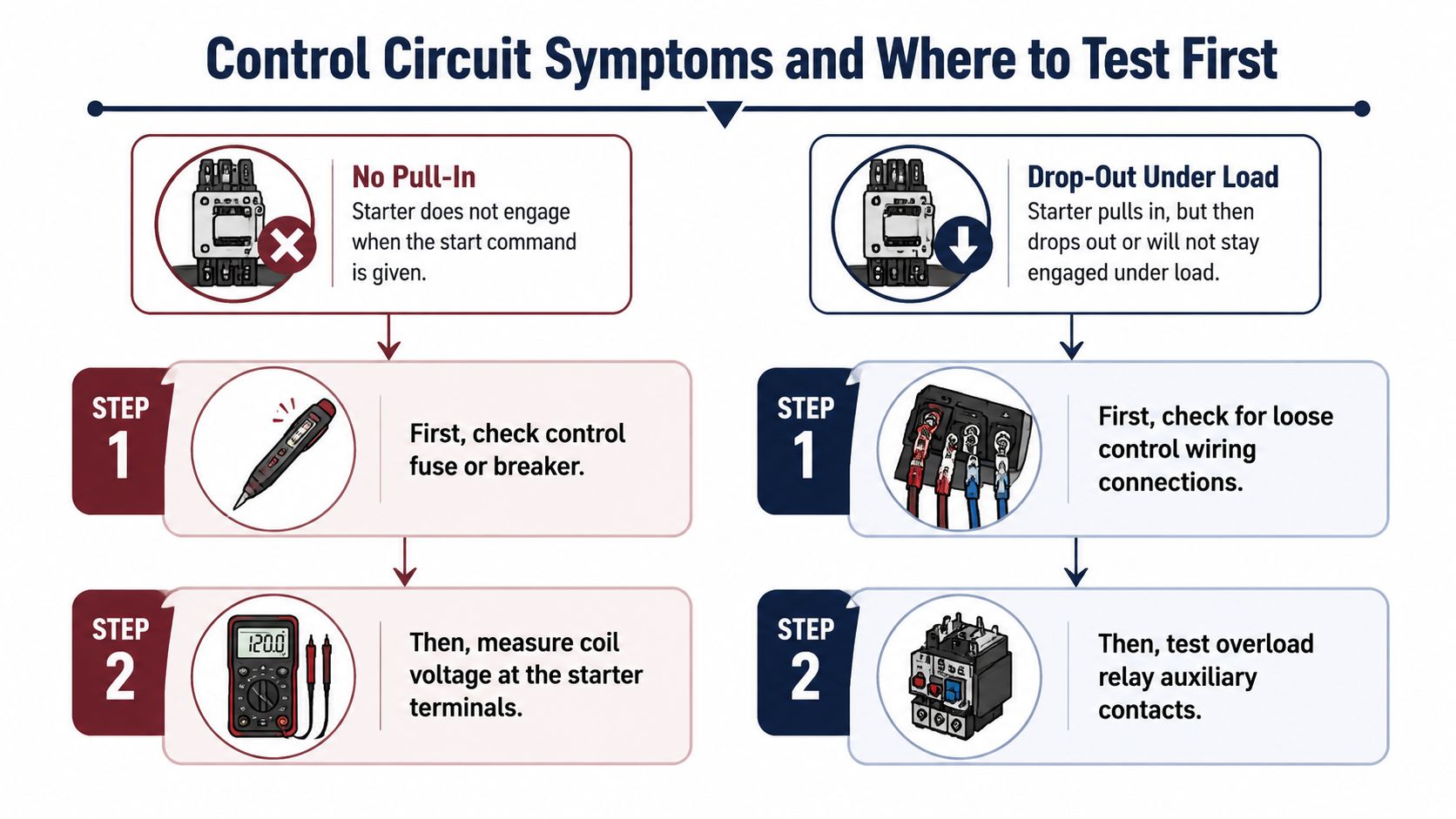
No pull-in
If nothing happens when the operator presses Start, inspect the control fuse or breaker first. A non-contact tester can indicate whether voltage is present, but it can't prove that the circuit can deliver current. Follow it with a two-lead measurement through the control path and finish at A1 and A2 with the start command held.
If the coil has the correct voltage but doesn't pull in, isolate power and test coil resistance against the nameplate or manufacturer's value. An open winding points to a failed coil. A coil that measures continuously but pulls in weakly may have mechanical damage, contamination, or an incorrect control voltage.
Trace the stop and start rung next. Check continuity across the stop device when it should be closed, then check the start device while it is pressed. Verify that the seal-in auxiliary contact closes and passes continuity after the contactor pulls in. On reversing starters, prove both electrical and mechanical interlocks. A broken stranded conductor at a door interlock or a loose crimp on a control terminal can create an intermittent open that looks like a bad contactor.
Chatter and dropout
A chattering coil usually has insufficient voltage at A1 and A2, a loose control connection, a failing pilot device, or a mechanical obstruction. Measure coil voltage while holding Start. If the reading collapses under command, measure across the control transformer secondary, across each control device, and across suspicious terminals to locate the voltage drop.
A grounded control conductor can produce phantom voltage. Confirm questionable readings with a low-impedance measurement method approved for the circuit, then inspect the conductor for insulation damage. In DC control circuits, confirm that the power supply and coil type are compatible. A control transformer that is overloaded by connected devices can also sag when the contactor is commanded.
For dropout under load without an overload trip, use a data-logging meter if available and watch the control voltage during motor acceleration. A supply sag can pull the coil below its holding level. Also check the seal-in auxiliary for contact bounce and inspect the overload relay's normally closed auxiliary contact. If that auxiliary opens, determine whether the relay tripped or whether its wiring is loose.
The decisive reading is at A1 and A2 during the failure. A correct reading there with clean continuity through the control devices sends the investigation to the power circuit, not back to the pushbutton.
Once coil voltage remains stable, the coil resistance is credible, the interlocks pass continuity, and the overload auxiliary is closed, stop repeating control tests. The next question is whether the contactor is delivering all phases to the motor.
<iframe width="100%" style="aspect-ratio: 16 / 9;" src="https://www.youtube.com/embed/A2IdXrJn0Ls" frameborder="0" allow="autoplay; encrypted-media" allowfullscreen></iframe>Contactor and Power Circuit Faults
With the control side proven, isolate and lock out the load before inspecting the power path. The line side of the contactor should provide the expected three-phase supply. Test each line-to-line pair at the contactor line terminals, then test line-to-ground where the circuit configuration and safety procedure permit.
A voltage reading alone isn't enough. A loose termination or damaged fuse connection may show normal voltage with no load and collapse when current flows. Check the line side, the load side, and the motor terminals under the same operating condition, then compare the readings with the recorded baseline.
Inspect the switching path
Look at every main pole. Pitting, erosion, welding, darkened insulation, and uneven contact wear indicate that the contactor has been working under abnormal stress or has reached the end of its serviceable condition. With the contactor de-energized, welded contacts can still show continuity. A contactor that remains closed after the coil is released is a safety and equipment risk, not a nuisance to work around.
If the design permits a controlled mechanical check, press the armature only under the site's approved isolation procedure and verify that each pole closes fully. Measure voltage on the load side with the contactor energized. One missing load-side phase, or a large drop across one pole, points to the contactor or its termination.
Don't overlook the coil's mechanical behavior. A coil that buzzes, pulls in slowly, or drops out after warming can have the wrong rating, a weakened winding, contamination in the magnetic circuit, or a damaged shading component where applicable. Check the coil resistance against its nameplate value with power removed. The resistance test is a screening test, not a substitute for measuring coil voltage while operating.
For a useful overview of internal switchboard inspection and repair considerations, review these motor switchboard internal structure repair tips.
| Test Point | Meter | Expected Reading | Fault Indication |
|---|---|---|---|
| Contactor line terminal pair | True-RMS meter | Stable supply voltage | Missing phase, sag, or upstream connection fault |
| Contactor load terminal pair, closed | True-RMS meter | Close to corresponding line-side voltage | Open or high-resistance main pole |
| Across each closed main pole | Low-resistance ohmmeter where suitable | Very low and consistent resistance | Pitted, contaminated, or damaged contact |
| Coil terminals A1 to A2 | True-RMS meter or DC meter as rated | Within ±10% of coil nominal | Control supply, wiring, or transformer fault |
| Motor lead current | True-RMS clamp meter | Comparable phase currents under the same load | Phase imbalance, load issue, or motor fault |
| Contactor with coil de-energized | Continuity or resistance test | Main poles open | Welded contacts |
After the poles pass voltage, confirm phase rotation before coupling the motor to the process. Then clamp each motor lead while running under load. A current imbalance above 10 percent is a warning threshold for investigating supply, termination, contactor, cable, and motor conditions. Treat that reading as a diagnostic boundary, not as permission to keep running a visibly hot or unstable machine.
Overload Relay Trips and Current Verification
An overload trip is a protective event. Record the trip indication before resetting the relay, especially if it stores trip current or cause. Repeated resets can turn a valid protection response into motor damage, so treat the reset button as an action, not a diagnostic test.
Check settings against the motor
Read the motor nameplate before adjusting the overload dial. The setting follows the motor's full-load current, not the starter's maximum rating. Confirm that the trip behavior matches the driven load, because normal acceleration and high-inertia starting place different thermal demands on the motor and relay.
For many starters, the commonly cited overload setting range is 115 to 125 percent of motor nameplate full-load current. Use the published coil and overload troubleshooting reference when checking that benchmark. Apply the equipment manufacturer's instructions and governing installation requirements where they specify a different value.
Trip class must match the duty. A relay that trips during every legitimate acceleration may be set for an unsuitable class. A relay that permits excessive heating may provide poor protection for the application. Class 10, Class 20, and Class 30 are common categories, but select among them from the motor duty, acceleration requirement, and approved protection design.
| Trip Class | Typical Application | Trip Time at 600% FLA |
|---|---|---|
| Class 10 | Normal acceleration and standard loads | Use the relay and manufacturer specification |
| Class 20 | Heavier starting duty | Use the relay and manufacturer specification |
| Class 30 | High-inertia or prolonged acceleration | Use the relay and manufacturer specification |
Verify current and environment
Run the motor under its normal process load and clamp each phase separately. Compare every reading with the nameplate FLA and with the other phases. Current that is high on all phases directs the investigation toward mechanical resistance, process load, incorrect motor selection, or an incorrect overload setting. One abnormal phase points toward supply imbalance, a loose termination, a contactor pole, cable condition, or a motor winding.
Use the current pattern to separate an overload problem from a contactor or supply fault. If one phase is low while another is high, inspect the corresponding power path before changing the relay setting. If all phases rise together, check the driven equipment and acceleration demand first.
Inspect enclosure temperature and the ventilation path. A blocked panel vent, heat from adjacent equipment, or high ambient conditions can make a thermal relay trip while the process still appears normal. Confirm that the reset mode suits the hazard. Manual reset is appropriate where unattended restart could create danger. Automatic reset belongs only where the process and safety design explicitly permit it.
Record the trip cause, overload setting, phase currents, ambient condition, and mechanical load together. Without that record, the next technician may reset the same fault and repeat the trip.
Controlled Restart and Post-Fault Verification
A controlled restart should reproduce the safe operating sequence, not bypass it. First confirm that the fault has been corrected, the overload is fully reset, the safety devices are made, and the control voltage is present at A1 and A2. Check that no temporary jumper, test lead, or defeated interlock remains in the circuit.
Energize the control circuit before issuing the run command. Listen for a clean contactor pull-in. Chatter, delayed closure, or immediate release means the restart stops there. Recheck coil voltage under command instead of allowing the contactor to hammer its contacts.
Watch the motor through acceleration
When the start command is applied, use the clamp meter to observe starting current and the transition to running current. Compare the result with the motor documentation and the known application behavior. Don't treat a single peak as proof of a fault without considering acceleration time, load inertia, and the starter type.
Once the motor runs, record each phase current, line voltage, rotation, sound, vibration, and temperature trend. Confirm that cooling fans, enclosure heaters, seal circuits, and process interlocks operate as designed. A motor that runs after a reset but lacks cooling or seal operation hasn't passed verification.
Use a written checklist during the observation period:
- Confirm the overload setting matches the motor nameplate and approved protection design.
- Verify all three phases remain present during starting and running.
- Check that the contactor remains mechanically stable without buzzing.
- Confirm safety interlocks and stop circuits respond correctly.
- Compare running current with the recorded baseline.
- Record the final readings and the exact corrective action.
The first steps after a trip should include preserving the last known state, identifying the trip path, and restoring operation only after the safety checks are complete. That discipline helps the next shift distinguish a verified repair from an assumed one.
Run the equipment through the actual production sequence if the process permits. A starter can behave normally with no load and fail once the driven machine reaches operating torque. Document the restart readings at the same test points used during diagnosis so future comparisons remain meaningful.
Common Mistakes and a Repeat-Trip Checklist
Most wasted hours come from starting at the wrong boundary. If the coil lacks voltage, work through the control circuit. If the coil is healthy but a pole doesn't pass power, inspect the contactor. If all phases reach the motor but current rises or the relay trips, investigate settings, load, environment, and motor condition.
Before closing the job, run this repeat-trip check:
- Control voltage: Measure A1 to A2 while the starter is commanded on.
- Control wiring: Recheck crimped terminals, door interlocks, seal-in contacts, and the overload auxiliary.
- Contactor condition: Inspect for pitting, welding, restricted travel, and heat damage.
- Overload setting: Match the relay to motor nameplate FLA and the approved application setting.
- Phase condition: Verify line voltage, phase rotation, and current on every phase.
- Insulation condition: Test phase-to-phase and phase-to-ground after a moisture event, using the site's acceptance criteria.
- Environment: Record cabinet temperature, ventilation condition, contamination, and nearby heat sources.
- Failure record: Log the trip indication, readings, operating state, and cycle context.
Don't replace a contactor while an upstream transformer is still causing coil chatter. Don't reset an overload without checking current and settings. Don't return restored power to production without proving rotation, interlocks, and running current. These three fault families remain the most useful map for keeping a short starter fault from becoming a repeat outage.
DUCHENG Industrial supports industrial electrical teams with structured diagnosis, controlled restarts, preventive maintenance, workshop repair, and on-site reconditioning for drive systems and related auxiliaries. For help preserving fault records, checking compatibility, planning a restart, or managing a difficult industrial motor-control issue, visit DUCHENG Industrial.