
Variable frequency drive troubleshooting made practical: pre-checks, symptom isolation, safe restart rules, and real fault scenarios.
The production line is down, the operator has reported a drive trip, and the display is showing a code that looks familiar enough to tempt an immediate reset. That reset may get the motor turning again, but it won't tell you whether the cause was a jammed load, a damaged motor cable, unstable incoming power, or heat building inside the cabinet. Variable frequency drive troubleshooting starts before the reset button and ends only when someone can justify a controlled restart or a clear escalation.
A reliable investigation treats the drive as one part of a system. You need evidence from the drive, motor, mechanical load, and incoming power, then you need to connect that evidence to the operating conditions at the moment of failure. This approach reduces repeat trips because it targets the fault pattern instead of treating the entire drive as the problem.
Table of Contents
- Why a Drive Trip Demands a Method, Not a Code Lookup
- Safety and Information Pre-Checks Before You Touch the Cabinet
- Reading Fault Codes, Event Logs and Drive Status
- Symptom Families That Point to Different Subsystems
- Building a Restart Decision That You Can Defend
- Time-Correlated Diagnosis Across Drive, Motor, Load and Power
- Two Field Cases That Show the Method in Practice
Why a Drive Trip Demands a Method, Not a Code Lookup
A fault code is a useful starting point, not a verdict. An overcurrent indication can result from an acceleration setting, a shorted motor lead, incorrect motor data, or a mechanical obstruction. An overtemperature indication may point to a failed fan or blocked airflow, but it can also reflect contamination, high ambient conditions, or sustained loading outside the intended duty.
The first question on a critical line should be, “What was the equipment doing when it tripped?” Record the running speed, commanded frequency, process state, product being handled, acceleration or deceleration phase, and any operator observation. A trip during an empty start means something different from a trip only when the machine reaches production load.
The four layers of isolation
A structured investigation separates the system into four practical layers:
- Drive: Review the fault, event history, parameters, cooling path, DC bus condition, and visible component health.
- Motor: Check insulation condition, winding balance, terminal connections, bearings, and nameplate data used by the drive.
- Mechanical load: Look for binding, blocked conveyors, seized bearings, incorrect tension, gearbox problems, and sudden process resistance.
- Power quality: Verify input voltage stability, loose terminations, upstream switching events, and supply disturbances.
This separation prevents a common waste of time, changing drive parameters when the driven machine is binding, or replacing the drive when the incoming supply is unstable.
Practical rule: Never treat “the drive tripped” as proof that the drive failed.
Reliability teams also need a consistent language for measuring repeat performance. MTBF means the statistical average time between failures, and it can be estimated from component FIT rates or from accumulated operating hours divided by failures in a fleet, as described in this industry reliability guide for AC variable-speed drives. That matters because a troubleshooting program should reduce repeat interruptions, not merely clear individual alarms.
The historical shift toward this method follows the technology. Practical industrial VFDs emerged in the late 1950s, heavier-industry adoption expanded in the 1970s, and microprocessor-controlled industrial drives appeared in 1982, according to this Control Engineering history of AC drives. As digital controls added richer status information and embedded protection, technicians gained better evidence for isolating overcurrent, thermal, and communication problems.
Safety and Information Pre-Checks Before You Touch the Cabinet
A technician shouldn't begin by probing terminals. The first task is to make the work safe and preserve the evidence that will explain the trip.
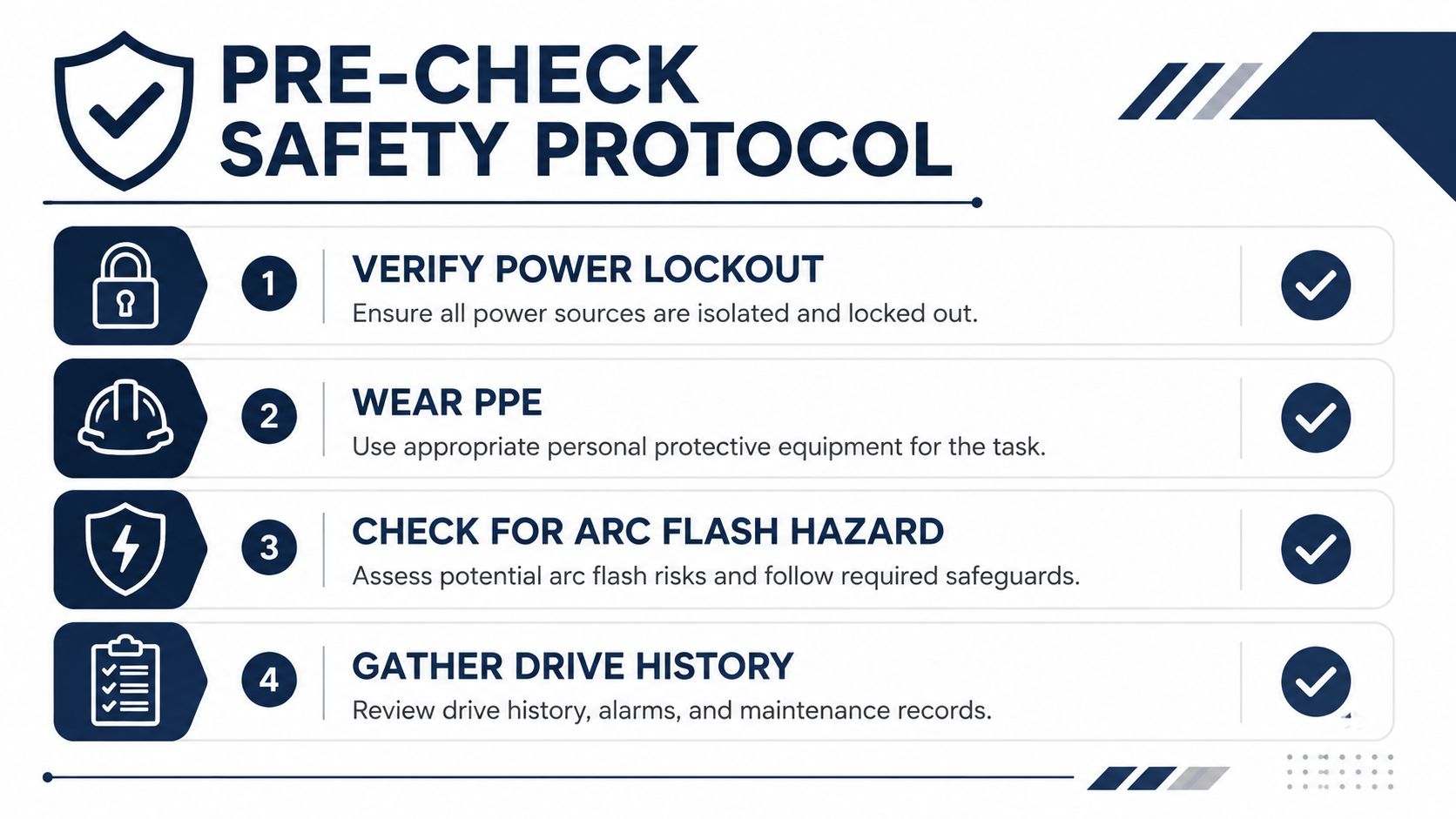
The non-negotiable routine
-
Verify the isolation boundary. Apply the site lockout and tagout procedure, isolate all relevant sources, and confirm that the motor cannot start from a remote command. A drive may have control power or auxiliary supplies that remain live after the main disconnect opens.
-
Allow stored energy to discharge. The DC bus can retain dangerous energy after isolation. Follow the manufacturer's discharge time and verify the absence of hazardous voltage with an appropriately rated meter and method. Never rely only on the display going dark.
-
Use the required PPE and approach boundaries. Arc-flash risk depends on the installation and site assessment, not on the apparent simplicity of the fault. Wear the PPE specified by the facility's electrical safety program, and don't open or test equipment outside your authorization.
-
Capture the drive identity. Photograph or record the manufacturer, model, rating, serial information, firmware where available, motor nameplate, parameter set, and cabinet condition. This prevents a later investigation from relying on memory or a mismatched manual.
-
Preserve the last known state. Before changing parameters, save the existing configuration if the equipment permits it. Note recent modifications, commissioning work, motor replacement, process changes, and control-system changes.
-
Interview the operator. Ask what the line was running, whether the fault appeared during start, acceleration, steady operation, or stopping, and whether the event is new or recurring. Ask about unusual noise, vibration, smell, heat, or visible process resistance.
For a concise site-side sequence, use this first-steps guide after a drive trip. It should complement, not replace, the site's electrical safety rules and the drive manufacturer's instructions.
What the supervisor should require
A good pre-check record includes the exact fault text, time of trip, operating state, reset attempts, and any alarm that appeared before the final trip. It also records whether the cabinet was dusty, wet, unusually hot, or obstructed, because environmental conditions often explain intermittent faults that a single electrical measurement misses.
Don't let production pressure turn an incomplete record into an informal restart. If the team can't establish the isolation status, preserve the event evidence, or identify who changed the operating conditions, the correct action is to stop and escalate.
Reading Fault Codes, Event Logs and Drive Status
The display is a diagnostic instrument. Use it to reconstruct the event before you use it to clear the event.
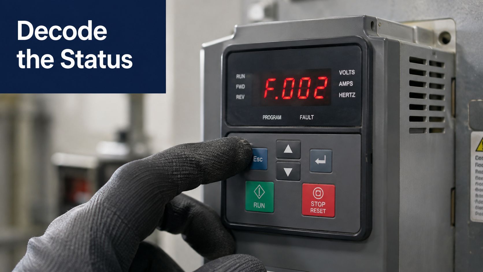
Capture first, reset second
Record the active fault, sub-code, warning history, running frequency, output current, DC bus indication, heatsink temperature if available, command source, and status word. Save the fault history or take clear photographs before pressing reset. A reset can remove the active display while leaving some history intact, but you shouldn't assume every useful value will remain available.
Event history becomes valuable when you compare several entries rather than reading only the latest code. Look for a repeating sequence, such as an input warning followed by undervoltage, or rising temperature followed by an overtemperature trip. The sequence often identifies the initiating condition more accurately than the final protective action.
Turn the code into a hypothesis
Treat each code as a question:
- Overcurrent: Did current rise during acceleration, at a particular speed, or when the process engaged? That points toward settings, motor condition, resonance, or load resistance.
- Overvoltage: Did the trip occur during deceleration or when the load was driving the motor? Investigate the ramp, braking path, and supply condition.
- Undervoltage: Did the input or DC bus fall before the trip? Check the upstream supply, terminations, and other equipment switching at the same time.
- Thermal fault: Did temperature rise gradually, or did the trip appear immediately after a fan or airflow problem? Inspect the cooling path and contamination.
- Communication or feedback fault: Did the drive lose a command, reference, network connection, or encoder signal? Check wiring, shielding, configuration, and control permissives.
The parameter set matters because the same code can have different implications under different control modes, current limits, motor data, ramp settings, and protection thresholds. Compare the current configuration with the last approved file, and don't “tune by feel” while the root cause remains unknown.
For multi-brand teams, consistent documentation is especially important. This guide to reporting fault codes across brands supports a common record containing the code, sub-code, timestamp, operating state, parameters, and corrective action.
A fault code narrows the search. It doesn't close the case.
Symptom Families That Point to Different Subsystems
The fastest diagnosis comes from grouping symptoms by the subsystem most likely to create them. This avoids chasing a code in isolation and makes the first measurement purposeful.
| Symptom Family | Typical Codes | First Check |
|---|---|---|
| Overcurrent and ground fault | OC, overload, GF, earth fault | Motor leads, insulation condition, acceleration behavior, and mechanical resistance |
| DC bus and overvoltage | OV, DC bus high, UV, DC bus low | Input stability, deceleration behavior, braking path, and loose supply connections |
| Thermal and environmental | OH, OT, fan or heatsink alarm | Filters, fans, airflow, cabinet temperature, dust, oil mist, humidity, and corrosion |
| Communication and feedback | Network loss, encoder loss, reference fault | Control wiring, shielding, termination, feedback supply, and command source |
| Motor-related symptoms | Motor overload, imbalance, unstable speed | Motor nameplate data, winding condition, bearings, cable routing, and load response |
Overcurrent and ground fault
Overcurrent requires a time-based question. If it occurs immediately on command, inspect motor wiring, insulation, incorrect motor data, and output-side switching. If it appears only during acceleration or at a particular process point, examine the ramp, torque demand, mechanical binding, and load transition.
A ground fault indication deserves a conservative response. Moisture, contamination, damaged cable insulation, and motor deterioration can all create a path to earth. Don't repeatedly reset a ground fault to see whether it clears. Isolate the motor and cable in accordance with the applicable test procedure, then interpret insulation results within the limits for that equipment.
DC bus and voltage symptoms
Overvoltage often appears when the motor or load returns energy to the DC bus during stopping or a driven condition. Check whether the deceleration command is too aggressive, whether the braking arrangement is correct, and whether the fault aligns with a process event.
Undervoltage points toward the supply side more often than the motor. Verify phase-to-phase input conditions under the relevant load, inspect terminations, and compare the trip timestamp with upstream switching or other large loads starting.
Thermal, communication, and motor symptoms
Thermal faults need a physical inspection, not just a temperature reset. Check fan operation, filters, heatsinks, cabinet airflow, contamination, and signs of corrosion. High humidity, dirt, corrosive agents, clogged filters, and fan failure can create a gradual decline that ends in a sudden trip.
Communication and feedback faults should be tested at the signal layer. Confirm the command source, cable condition, shielding, connectors, addressing, and feedback supply. If the drive runs locally but not from the control system, that difference is useful evidence.
Motor symptoms can mimic drive failure. A motor that runs unevenly, draws abnormal current, or trips only under process load may have a mechanical or winding problem even when the drive electronics are healthy.
Building a Restart Decision That You Can Defend
A reset is an action, not a diagnosis. The supervisor should be able to explain why the equipment was safe to re-energize, what evidence supported the decision, and what observation would trigger an immediate stop.
Define the no-go conditions
Keep the drive locked out and escalate when any of these conditions exists:
- Ground fault indication: Treat it as an unresolved insulation, cable, motor, or contamination problem.
- Visible component damage: Cracked semiconductors, burned terminals, bulging or leaking capacitors, carbon tracking, or severe corrosion require deeper assessment.
- Repeated protective trips: Repeated overcurrent, overvoltage, undervoltage, or thermal trips without a verified corrective action are not a restart strategy.
- Uncertain isolation: Stop if stored energy, backfeed, remote start paths, or auxiliary supplies aren't fully controlled.
- Unexplained mechanical resistance: Don't ask the drive to prove that a jam is still present.
- Missing evidence: If the team cleared the history and can't establish what happened, use a conservative escalation decision.
Use a controlled restart sequence
When the fault cause is understood and the equipment is safe, proceed in stages:
- Correct the identified cause. Tighten or repair the approved connection, restore cooling, remove the mechanical obstruction, correct the documented parameter issue, or address the supply problem.
- Verify the motor and cable. Complete the required insulation and continuity checks with the motor isolated as appropriate. Confirm that test methods won't expose the drive electronics to an unsuitable voltage.
- Confirm direction and permissives. Use a controlled local or maintenance mode where authorized. Confirm that the motor will rotate safely and that interlocks, guards, valves, and process conditions are ready.
- Stage the ramp. Start at a controlled condition and observe current, frequency, DC bus behavior, vibration, sound, and process response. Don't return immediately to full production demand.
- Watch for recurrence. Compare the new event with the original timestamp, current, temperature, and operating state. Stop if the original pattern returns.
The restart record should identify who approved the test, what was changed, which measurements were taken, and what limits would stop the test. This creates a defensible decision rather than an undocumented gamble.
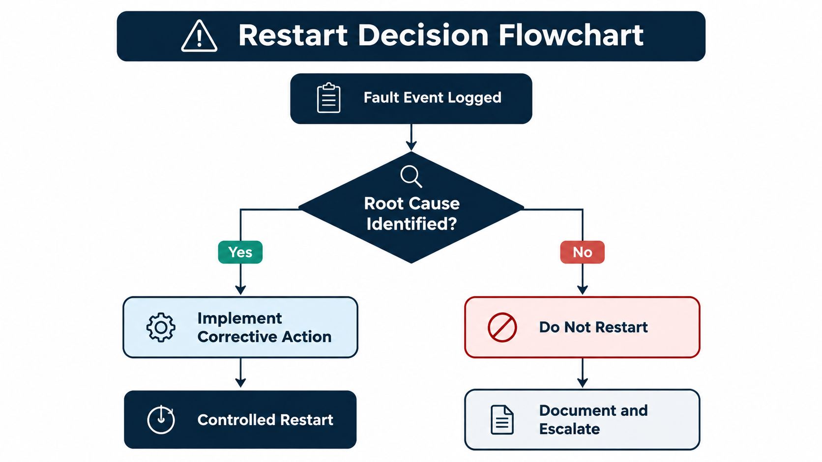
A short visual reminder can help supervisors keep “root cause identified” separate from “fault cleared.”
<iframe width="100%" style="aspect-ratio: 16 / 9;" src="https://www.youtube.com/embed/ttLjee9R7rY" frameborder="0" allow="autoplay; encrypted-media" allowfullscreen></iframe>Don't use a successful restart as proof that the equipment is healthy. Intermittent faults often disappear under different load, temperature, or production conditions.
Time-Correlated Diagnosis Across Drive, Motor, Load and Power
The strongest evidence is often the relationship between events. A fault at a particular production state, shift change, weather condition, or time of day may reveal more than the code itself.
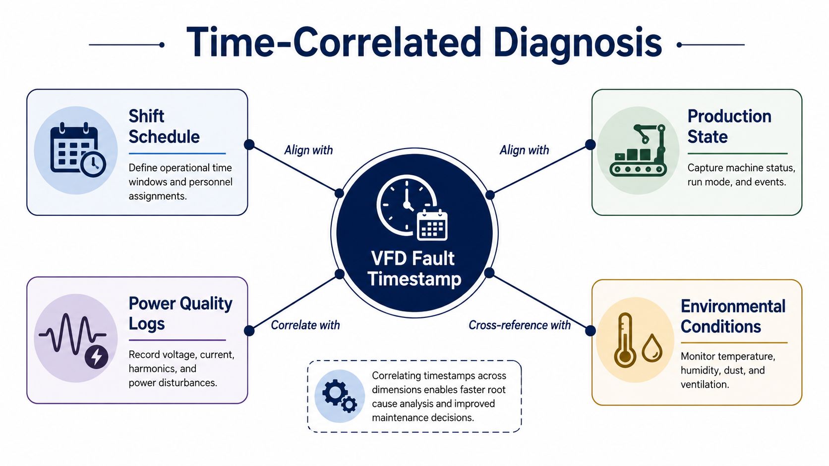
Build one event timeline
Bring the drive history together with:
- Shift schedule: Note whether the trip follows a handover, cleaning activity, or maintenance intervention.
- Production state: Record product, batch, machine speed, valve position, conveyor loading, and changeover status.
- Power quality logs: Align the timestamp with voltage fluctuations, upstream switching, and other large equipment starting.
- Environmental conditions: Compare cabinet temperature, humidity, dust, salt exposure, and weather with the event history.
The purpose isn't to collect data for its own sake. It is to test competing explanations. A trip that occurs only when a product enters an extruder points toward load behavior. A trip that follows a supply disturbance across several drives points toward power quality. A thermal trip that follows humid, contaminated conditions points toward cabinet health.
Separate the four root-cause layers
If the procedure and equipment allow it, technicians may isolate the motor from the drive and test the drive in a controlled manner. That step can help separate an output-side motor or cable issue from a drive-side problem, but it must follow the manufacturer's instructions and site safety requirements.
Inspect the DC bus, rectifier diodes, inverter switching devices, capacitors, and cooling system for evidence of component stress. Check input voltage stability and investigate harmonic distortion where power quality is suspected. The investigation should also consider whether the drive's duty rating matches the motor and load, particularly where repeated trips occur under sustained process demand.
Condition-based troubleshooting is especially important for aging or harsh-environment cabinets. Contamination, thermal cycling, fan deterioration, and capacitor degradation may not produce one clean initiating code, but they can reduce operating margin until a normal process event triggers protection.
Two Field Cases That Show the Method in Practice
Consider an anonymized tire-plant extruder with a recurring overcurrent trip. The first response was a parameter review, because the code appeared during acceleration. The team then preserved the fault timestamps, checked the motor current trend, interviewed the operator, and inspected the machine at the exact production state associated with the trip.
The evidence showed that the drive was responding to a mechanical binding event upstream. With the obstruction removed and the mechanical path checked, the motor accelerated normally under a controlled test. The restart was justified because the cause had been identified, the corrective action was completed, and the original symptom did not return during staged operation.
The second case involved a coastal steel-plant drive with recurring thermal trips. A reset restored operation temporarily, which made the first response look successful. A cabinet inspection later found salt-laden contamination and restricted cooling surfaces, so the apparent drive fault was a condition developing around the drive.
What the two cases teach
The extruder case demonstrates when a restart can be appropriate. The fault was correlated with a repeatable process condition, the mechanical cause was found, and the controlled restart tested the suspected failure path.
The steel-plant case shows why “it ran after reset” is weak evidence. Contamination and heat-driven aging require cleaning, inspection, cooling verification, and an assessment of components such as capacitors, diodes, and IGBTs. Depending on condition and equipment type, on-site reconditioning may be more practical than shipping a large drive or replacing a serviceable unit, but that decision belongs after a documented inspection and functional test.
For facilities that need support beyond a code lookup, DUCHENG Industrial provides multi-brand VFD troubleshooting, repair, on-site reconditioning, commissioning support, and spare-part compatibility checks. Send the drive model, fault record, nameplate information, and evidence from the event timeline so the service team can assess the fault as a system problem rather than a display message.