
Variable Speed Drive DC Motor explained: how speed control works, drive topologies, DC vs AC drives, retrofit options and maintenance checks for engineers.
The production line still runs well, but its DC drive has started tripping during deceleration. You've found a replacement controller, yet nobody has confirmed whether it can brake the load, work with the existing field supply, or use the spares already in your stores.
Choosing a variable speed drive for a DC motor means answering those questions together. The right decision starts with how the machine accelerates, stops and reverses, then checks whether the existing motor and drive hardware are worth keeping.
Table of Contents
- How a Variable Speed DC Drive Controls Speed
- Drive Topologies from One to Four Quadrants
- Choosing Regenerative Braking for Your Duty Cycle
- Where DC and AC Drives Each Win
- Repair, Upgrade or Replace an Aging DC Drive
- Maintenance Routines That Keep a DC Drive Running
- Confirm the Drive Type Before You Specify or Retrofit
How a Variable Speed DC Drive Controls Speed
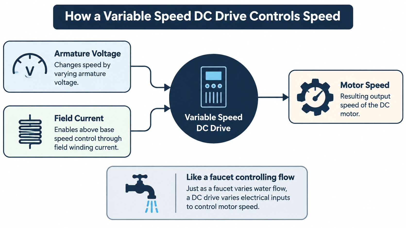
A variable speed DC drive controls a wound-field motor mainly through armature voltage and field current. The armature is the rotating electrical circuit that produces torque. The field winding establishes the magnetic field it works against.
Think of armature voltage as a tap on a water pipe. Opening the tap increases flow; increasing armature voltage lets the motor run faster. The analogy isn't exact, because motor current follows the torque demanded by the load, but it separates the speed command from the effort needed to move the machine.
Below base speed, the drive normally maintains full field strength and raises or lowers armature voltage. With suitable current capacity, the motor can deliver approximately constant torque through this region. A loaded feeder, for example, needs turning effort even when its operator selects a slow production speed.
The diagram separates these control functions.
What changes above base speed
Once the armature reaches its permitted operating voltage, demanding more voltage isn't the next step. A compatible drive can reduce field current, weakening magnetic flux so the motor can rotate faster.
This field-weakening region trades torque for speed. Power can remain approximately constant, but available shaft torque falls. That can suit a machine-tool spindle running faster under a lighter cutting load; it may not suit a conveyor that still needs substantial torque.
There's no universal field-weakening multiplier to apply to an unidentified motor. Use its approved speed envelope, field characteristics and mechanical limits rather than treating the controller's maximum setting as permission to run faster.
How feedback holds the selected speed
A tachometer or encoder tells the drive how fast the shaft is turning. The controller compares that signal with the setpoint and adjusts its output when the process load changes.
Feedback doesn't create extra motor capacity. If the load demands more torque than the current limit permits, the controller can't maintain speed indefinitely. Cooling also matters during sustained slow operation, particularly when the motor's ventilation depends on shaft speed.
Control levers and the speed range each one covers
| Control lever | What it changes | Speed range | Torque behaviour |
|---|---|---|---|
| Armature voltage | Voltage across the armature | Zero to base speed | Constant torque up to rated current |
| Field current (field weakening) | Magnetic flux in the field winding | Above base speed to the motor's approved maximum | Torque falls as speed rises; power stays near constant |
| Speed feedback loop | Compares actual speed with set speed | Whole approved operating range | Corrects speed changes within available torque and current limits |
Drive Topologies from One to Four Quadrants
A drive's quadrants describe combinations of rotation direction and torque direction. Torque acting with rotation drives the load. Torque acting against rotation brakes it.
That distinction prevents a common purchasing mistake: assuming that a controller capable of changing speed can also stop a moving load electrically. Speed regulation and braking capability aren't the same specification.
Start with the simplest operating duty
A single-quadrant drive supplies forward motoring torque. When the run command disappears, the machine normally coasts unless a separate braking arrangement acts on it. This can be a sensible choice for a pump, fan or simple conveyor where stopping time isn't tightly controlled.
A two-quadrant arrangement adds another operating capability. In the forward-running configuration considered here, it provides forward motoring and regenerative braking. However, quadrant terminology alone isn't enough: some arrangements cover different torque and speed combinations, so confirm the manufacturer's operating diagram.
A four-quadrant drive provides motoring and electrical braking in either rotation direction. A reversing rolling mill or test stand needs that flexibility because both the direction of movement and the direction of torque change during operation.
DC drive topologies compared by quadrant and braking
| Topology | Operating quadrants | Braking method | Typical applications | Trade-off |
|---|---|---|---|---|
| Single-quadrant (non-regenerative) | Forward motoring only | Coast to stop or mechanical brake | Fans, pumps, simple conveyors | Simplest converter; no energy returned to supply |
| Two-quadrant | Motoring plus regenerative braking in one direction, for this configuration | Regenerative braking one way | Winders, some hoist arrangements | Added converter capability; verify the actual quadrant map |
| Four-quadrant (fully regenerative) | Motoring and regenerative braking in both directions | Regenerative braking both ways | Reversing rolling mills, test stands, lowering hoists | Greatest operating flexibility; more protection and commissioning work |
Match the converter to the installation
Industrial DC drives commonly use controlled thyristor bridges to convert the incoming AC supply into a controlled DC output. Single-phase bridges can serve smaller duties, while three-phase bridges suit larger industrial power requirements.
Bridge selection also affects the incoming supply arrangement, current characteristics, protective devices and cabinet design. A replacement isn't electrically interchangeable just because its rated shaft power matches the old unit.
Moving to more operating quadrants usually adds hardware, interlocks and commissioning checks. Those additions are justified when the process needs the capability, not because a more elaborate converter sounds preferable.
Selection rule: Choose the operating quadrants from the required torque and motion in every machine state, including stopping and lowering, rather than from motor size alone.
Keep a shortlist based on actual operating modes. If the machine only runs forward, compare non-regenerative operation with forward regenerative braking. If it must reverse under controlled torque, assess a fully reversible arrangement.
Choosing Regenerative Braking for Your Duty Cycle
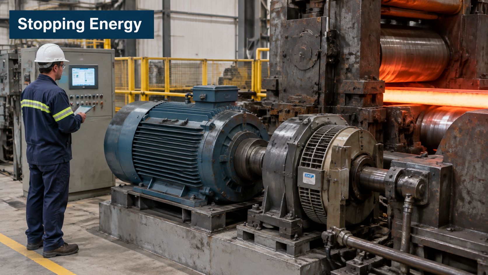
A decelerating DC motor becomes a generator as soon as motoring torque is removed. The stored energy has to go somewhere: back to the supply, into a braking resistor, or into friction material. A heavy roll stand or flywheel-loaded winder can keep turning long after the power is cut, and the machine's permitted stopping time decides which destination is acceptable.
Inspect the motor, driven equipment and cabinet as one system before selecting braking hardware.
Apply the duty-cycle test
- Establish stopping energy. Calculate the kinetic energy to be removed using the combined motor and load inertia referred to the motor shaft. Include energy introduced by an overhauling load, such as descending material.
- Record stopping frequency. An occasional stop and repeated production deceleration impose different thermal and economic demands. Use the actual operating sequence, including interrupted cycles.
- Identify reversing and lowering states. A conveyor allowed to coast may need no electrical braking. A lowering hoist needs a controlled means of managing the descending load, while a repeatedly reversing test stand needs bidirectional torque control.
- Check the required speed envelope. Verify motor insulation, commutation, overspeed limits and load torque before approving above-base-speed braking.
- Assess supply strength. Regeneration sends energy back to the AC supply. Review the transformer, supply impedance and other connected loads rather than assuming every connection can support the same converter behaviour.
Fit DC-side fuses on regenerative drives, particularly on weak supply systems, and coordinate them with the converter's protection requirements. The machine's circuit diagrams and manual show the intended arrangement. On a retrofit, confirm that spares for the chosen arrangement, resistors, contactors and fuse types included, remain available for the drive's remaining life.
Compare the whole stopping arrangement
Each destination carries a running cost. A mechanical brake introduces wear and inspection work. A compatible dynamic-braking circuit sends energy into resistors, requiring heat management and physical space; it isn't a feature that can be assumed on any DC drive. Regeneration avoids the resistor heat but pushes the energy problem upstream to the supply.
A hoist keeps a separate requirement: electrical braking does not replace an appropriate holding and safety-brake arrangement. Assess what happens if the drive trips or the supply disappears mid-stop.
Use this demonstration alongside the machine's own circuit diagrams and operating instructions.
<iframe width="100%" style="aspect-ratio: 16 / 9;" src="https://www.youtube.com/embed/stq2E3sZYg0" frameborder="0" allow="autoplay; encrypted-media" allowfullscreen></iframe>Regeneration is most attractive when recoverable braking energy is substantial and frequent, or when controlled deceleration is a process requirement. Where stopping energy is small and coast-down is acceptable, the extra equipment and commissioning work may offer little benefit.
Where DC and AC Drives Each Win
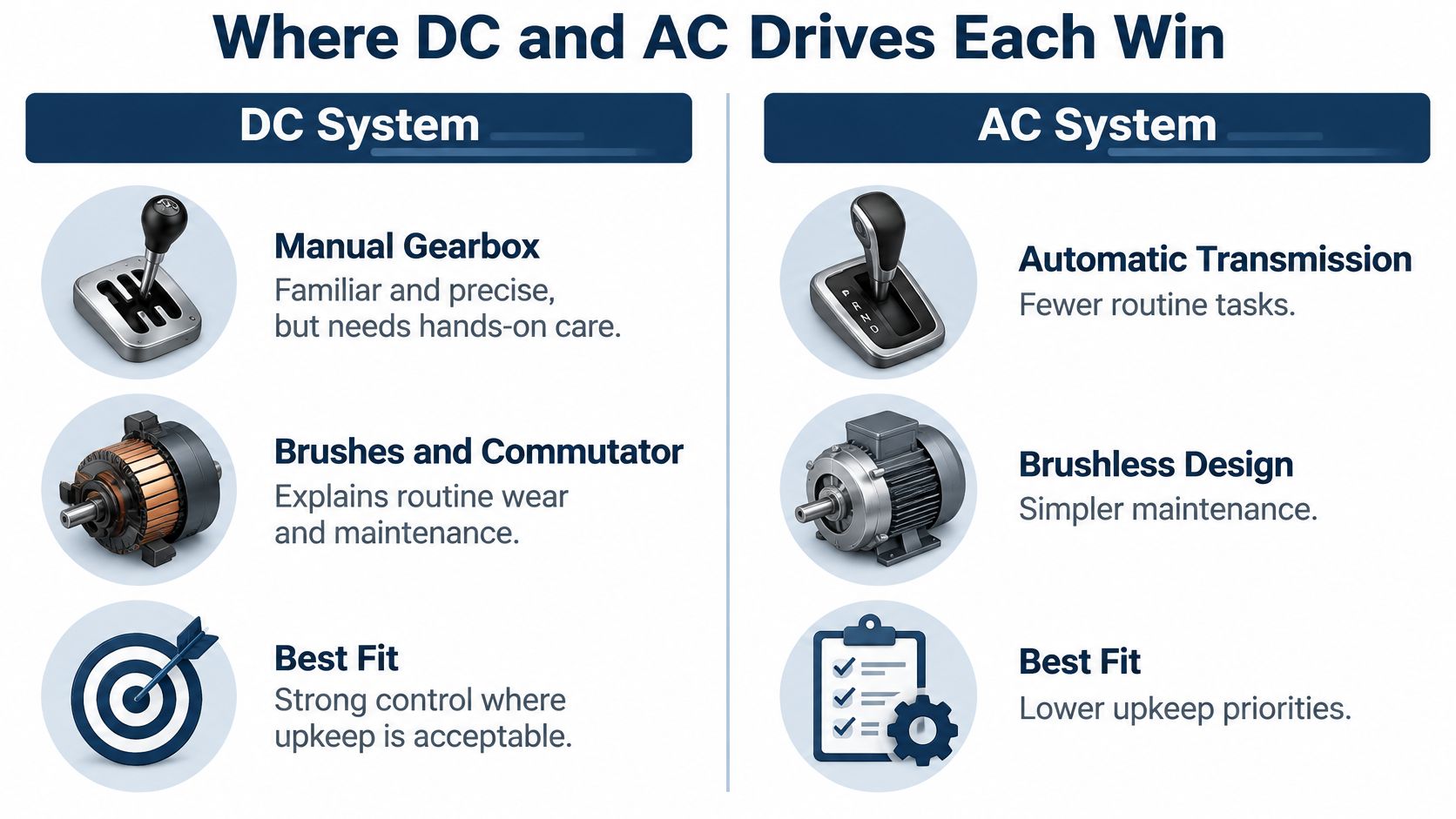
Brush replacement and commutator dressing are the routine DC tasks an AC conversion removes. That service difference sits at the heart of most DC-versus-AC decisions, so it deserves to be stated plainly before anything else. Both technologies can deliver demanding industrial performance when the motor, converter, feedback and cooling are matched to the application.
In a conventional DC motor, carbon brushes contact a commutator to transfer current into the rotating armature. That contact produces wear and dust, and poor commutation can cause damaging sparking. At higher speed, the motor must still reverse current successfully within the armature coils, which places a practical limit on operation.
Compare complete systems
A squirrel-cage induction motor has no brush-and-commutator assembly. Its variable frequency drive uses a pulse-width-modulated inverter to control the electrical supply to the motor, with vector control available for demanding torque regulation.
The infographic highlights the different service priorities.
DC drive and AC VFD compared on the criteria that matter in service
| Criterion | DC drive with DC motor | AC VFD with induction motor |
|---|---|---|
| Motor construction | Brushes and commutator | Squirrel-cage rotor, no brushes |
| Torque at zero speed | Full torque with suitable current control and cooling | Full torque with suitable vector control, feedback and cooling |
| Routine maintenance | Brush, commutator, dust, bearing and cooling service | Mainly bearings and cooling equipment, plus drive inspection |
| Motor availability and cost | Specialist sourcing; obtain repair and replacement quotations | Standard industrial motors are commonly stocked; compare installed cost |
| Four-quadrant operation | Established option in heavy industry | Supply regeneration needs an active front end or regenerative unit |
| Typical role today | Legacy lines and proven heavy-duty duties | Common starting point for new installations |
Where retaining DC makes sense
A proven DC motor may already match the gearbox, foundations, coupling and process exceptionally well. Keeping it can avoid mechanical alterations and reduce the scope of a shutdown, provided its condition and support arrangements remain acceptable.
Whichever direction you are weighing, run the same four checks. How much stopping energy does the duty produce, and how often must the drive absorb it? Is the supply strong enough to support the converter behaviour the application needs? And will parts and repair support exist for the machine's remaining life? A DC machine that clears all four can be the rational choice even where AC equipment would be simpler to buy.
One confusion worth clearing up early: motor-side braking and returning energy to the mains are different things. An AC drive may produce braking torque while dissipating energy through a suitable braking circuit, without any regenerative supply front end. An ordinary AC motor with a basic sensorless controller also may not reproduce every low-speed or standstill requirement of the existing system.
For a new installation, AC is usually the starting option to evaluate. For an established line, compare the complete installed change, including mechanical work, controls, shutdown exposure and future maintenance, before retiring serviceable DC equipment.
Repair, Upgrade or Replace an Aging DC Drive
A DC drive comes up for review after 25 years on the same line: the armature and commutator still measure healthy, the thyristor bridge tests clean, and the control boards fail intermittently with no spares available. One machine, three different answers. The motor only needs routine care, the bridge can stay, and the controls need replacing. Age alone cannot make this call; condition and support status decide it subsystem by subsystem.
Support usually tapers rather than switches off. Spares, repair help and factory backing commonly narrow as a product line matures, so a supported retrofit can restore maintainability without discarding every major component.
In a pulp-and-paper example described by Processing magazine's industrial-drive lifecycle article, a retrofit produced 2,215 kg of associated CO2 emissions versus 6,405 kg for a new installation, more than 65% lower. That figure belongs to that application; run the same comparison on your own scope rather than borrowing the result.
Assess condition before choosing scope
Start with the motor's insulation, commutator and remaining mechanical life. Then inspect the thyristor bridge and control boards, cooling passages, fans and capacitors where fitted. A sound controller cannot compensate for a motor that needs major rehabilitation, so find the weakest subsystem first.
Then map support and duty together. Establish spare-part availability, process criticality, required network interfaces and failure history, recording whether faults are isolated, repeat under the same load condition, or follow overheating and contamination. When the work goes to a service provider, the request moves faster if it includes the drive brand, exact model code, rated power and voltage, the fault code exactly as displayed, when the fault occurs, and the operating environment.
A partial upgrade often keeps a healthy motor and power bridge while replacing controls and adding monitoring. Apply the same selection test that chooses drive topology: how much stopping energy the duty produces, how often it brakes, whether the supply can absorb returned energy, and whether parts remain available. An upgrade that changes braking behaviour changes the hardware around the bridge, so confirm electrical interfaces, firing arrangements, feedback compatibility and protection coverage before assuming it can stay.
Retrofit paths compared on the factors that drive the decision
| Decision factor | Repair in place | Partial upgrade | Full replacement |
|---|---|---|---|
| Outage risk | Lower scope when the fault is isolated | Planned shutdown with interface testing | Broader commissioning and integration exposure |
| Motor reuse | Motor kept if serviceable | Motor usually kept after checks | Motor retained, re-matched or replaced |
| Carbon impact | Limited material replacement; assess repair scope | Below new installation in the cited case | New equipment manufacture and installation must be assessed |
| Control and cyber exposure | Existing exposure remains unless addressed | New links require security and compatibility review | Current platform still needs secure configuration |
| Typical trigger | Isolated fault with parts available | Support constraints or monitoring requirements | Hardware or controls can no longer be supported |
Use monitoring to test the decision
Trend current, voltage, temperature, vibration, fault history and load behaviour against operating states. A current rise during a known production change means something different from a rise at unchanged output. Keep timestamps aligned so engineers can compare mechanical symptoms with electrical events.
Monitoring should answer a maintenance question, not merely create a dashboard. Before adding network connections, define access permissions, interoperability requirements, data ownership and a spare-parts plan.
The documented DCS800 emergency recovery case shows this reasoning in practice: engineers investigated an existing DC installation rather than treating discontinued support alone as a replacement instruction.
The trigger row of the table above condenses the decision rule, and the drive-type confirmation later in this article applies the same test once more.
Judge the chosen work by downtime, recurring faults, energy performance and commissioning duration. Include the remaining motor life and the consequences of an unsuccessful restart in the approval decision.
Maintenance Routines That Keep a DC Drive Running
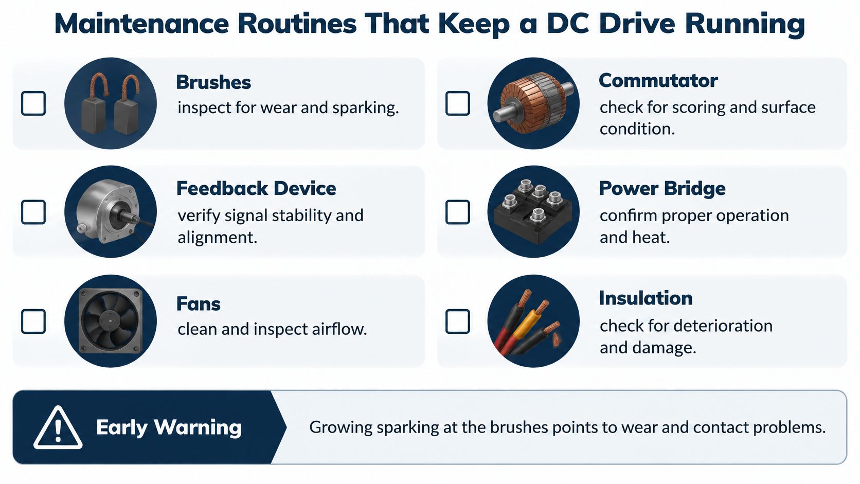
Suppose operators report growing sparking at the brushes, but the drive displays no useful fault. Don't start by replacing the control board. Inspect brush condition, contact pressure, seating, commutator condition and contamination before widening the diagnosis to electrical loading and control behaviour.
Maintenance works best when each observation leads to a defined check. Speed hunting, heat and sparking are symptoms, not component diagnoses.
Use the visual checklist to organise the inspection scope.
Build the shutdown checklist
Apply isolation, lockout and verification of absence of voltage before intrusive work. Prevent driven equipment from back-driving the motor, and separate de-energised inspections from any authorised live testing.
- Measure brush length. Compare each brush with the motor manufacturer's minimum. Record uneven wear by brush position rather than replacing brushes without investigating the pattern.
- Check spring pressure and seating. Use the specified inspection method and confirm free movement in the holders. Poor contact can produce local heating and unstable current transfer.
- Inspect the commutator and remove dust. Look for scoring, abnormal discolouration and surface damage. Use an appropriate industrial vacuum and approved cleaning method rather than spreading conductive dust through the machine.
- Verify feedback integrity. Check tachometer or encoder mounting, coupling, wiring and signal stability. Investigate intermittent speed feedback before changing speed-loop tuning.
- Inspect protective devices. Check armature and field fuses, plus the specified DC-side protection on regenerative equipment. Replace only with correctly coordinated types, and investigate the cause of operation.
- Restore cooling performance. Examine fans, filters, heatsinks and motor ventilation paths. Confirm airflow direction and fan operation after maintenance.
- Check for abnormal heating. Qualified personnel can thermally inspect bridge and terminal connections under representative load using the site's electrical safety procedure. De-energise before correcting connections.
- Test winding insulation. Disconnect sensitive electronics and follow the motor manufacturer's test-voltage instructions for armature and field circuits. Record test conditions so later readings are comparable.
- Back up parameters. Save an identifiable configuration, firmware information and feedback settings, with an accessible restoration record.
Set intervals from operating conditions
Use the manufacturer's schedule as the baseline, then adjust inspection frequency to dust exposure, operating duty and recorded deterioration. A clean standby machine and a heavily loaded motor in conductive dust shouldn't receive identical attention.
Early warning: Record the symptom, operating state and first inspection result together. A note that says only “motor checked” won't help the next technician identify a developing fault.
After maintenance, confirm guards, connections, feedback polarity and permitted operating settings before a controlled return to production.
Confirm the Drive Type Before You Specify or Retrofit
A retrofit decision stands or falls on the quality of the equipment record behind it. Capture the motor and the drive separately: the motor's ratings tell you what the load demands, while the drive's model and option identifiers tell you what the existing converter can deliver.
Use a guide to reading a drive nameplate to organise the identification details, then attach photographs that clearly show terminal markings and installed options.
Prepare the assessment input sheet
- Motor identification. Record base speed, rated armature voltage and current, field rating, maximum permitted speed and feedback-device details. Include any separate motor ventilation arrangement.
- Operating duty. Document stopping energy per cycle, cycles per hour, reversing or lowering operation, required stopping time and the requested above-base-speed range. Mark calculated values separately from measured observations.
- Supply conditions. Record the connection point, transformer information, available supply-strength information and relevant protection drawings. Identify operation from a generator or other constrained source.
- Support position. List installed spares, verified compatible replacements, available parameter backups and components that can no longer be obtained.
- Fault information. Include the drive brand, exact model code, rated power and voltage, the fault code exactly as displayed, when it occurs and the operating environment.
Define what the review must decide
Select a provisional topology, then test it against the four checks the input sheet was built to answer. Stopping energy per cycle and cycles per hour decide whether regenerated energy must return to the supply or can be absorbed in the armature circuit. Reversing and lowering duty decide the quadrant count. Supply strength decides whether the converter can run without disturbing other loads on the same connection point. The support position decides how long any choice can realistically stay in service.
Approve a replacement only after voltage, power, stopping duty and supply strength have each been checked.
At the end of an aging system's service life, the first question is which parts can be maintained and refurbished before whole-unit replacement is considered. That assessment needs to distinguish a recoverable component fault from a wider support or machine-condition problem, because each points to a different scope of work.
Send the completed input sheet, fault history and drawings to a drives specialist for an on-site review. Request a defined work scope, commissioning checks and spare-parts requirements so maintenance and operations can approve the same recovery plan.
DUCHENG Industrial provides multi-brand VFD diagnosis, repair and upgrade assessments, and can review existing drive installations on site. Visit DUCHENG Industrial with your equipment details and duty-cycle record to discuss an on-site assessment of what can be repaired, refurbished or replaced.