
High voltage electric motor guide covering characteristics, insulation systems, VFD interaction, harsh-environment risks, and maintenance strategies
The compressor trips during a production run, and the control-room alarm points to the medium-voltage drive. The shift team wants the line back quickly. The electrical supervisor wants to know whether the fault came from the drive, the motor, or the machine it turns. Resetting without that distinction can turn a recoverable trip into a damaged winding, a failed power component, or a second outage.
A high voltage electric motor is the rotating core of a connected system: supply, drive, cables, protection, motor, coupling, and driven load. Reliable decisions depend on the condition of that whole chain, not just the motor's nameplate or the drive's fault code.
Table of Contents
- What a High Voltage Electric Motor Really Does in Your Plant
- Core Characteristics That Define a High Voltage Electric Motor
- Efficiency Benchmarks Beyond the Nameplate
- Insulation Systems and Partial Discharge Monitoring
- Starting, VFDs and the Safe-Restart Decision
- Reliability Risks in Harsh Environments
- Maintenance, On-Site Reconditioning and Lifecycle Renewal
- A Practical Lifecycle Checklist for Plant Teams
What a High Voltage Electric Motor Really Does in Your Plant
A process pump maintains flow; a fan keeps combustion or ventilation within operating limits. Their motors carry process duties that affect the whole plant. Losing either machine can force operators to reduce load or stop production, even when the electrical fault is repairable. Maintenance decisions therefore have to account for the process consequences as well as the equipment condition.
The scale of that responsibility is reflected in the U.S. Department of Energy market assessment: production-process motor systems consumed 679 billion kWh in 1994, equivalent to 23% of U.S. electricity sold, while including industrial HVAC raised consumption to 747 billion kWh, or 25% of national electric sales, and approximately 69% of industrial electricity use. These are historical figures from 1994, not a current measurement of plant electricity demand.
Purchase price is only one part of the motor's lifecycle cost.
Operating cost, availability, and the cost of interrupted production shape the practical choice. A motor and drive must work together under the actual load and operating conditions. After a trip, that means deciding whether the evidence supports a restart, further testing, or corrective work. On-site cleaning or reconditioning may address contamination, but it cannot be assumed to resolve winding damage or a drive-control fault.
Five failure families to keep in view
Use these categories to organize the investigation rather than treating each as an isolated cause:
- Insulation: winding deterioration, contamination, or electrical stress.
- Drive interaction: switching faults, control problems, or motor-drive compatibility.
- Environment: salt, dust, moisture, heat, or chemical contamination.
- Bearings: lubrication problems, mechanical damage, or electrically induced wear.
- Protection coordination: settings or trip logic that fail to distinguish a transient from a developing fault.
The categories overlap. Contamination inside a drive cabinet may cause a trip while the motor remains serviceable. Winding deterioration may instead trigger protection before further damage occurs. The repair scope depends on which condition the inspection and test results support, not just on which device reported the alarm.
Practical rule: Treat the alarm as evidence, not a diagnosis. Review the event history, inspect the affected equipment, and establish what caused the trip before authorizing a restart.
Core Characteristics That Define a High Voltage Electric Motor
Start with the voltage class. Industrial motors are often described by their nominal supply voltage, with 6 kV and 11 kV common examples in high-voltage plant discussions. The right class depends on the plant's electrical distribution and the load, not on a simple rule that every large machine needs the highest available voltage. Think of voltage class as the lane a motor travels in: it determines the electrical infrastructure around it, including switchgear, cables, protection, and drive arrangements.
The insulation system is the boundary that keeps the electrical energy where it belongs. If voltage class is the lane, insulation is the set of markings that keeps conductors separated and prevents unwanted electrical paths. Its design and condition matter during normal operation, startup, switching, and VFD operation. A motor can have sound mechanical parts yet still be unfit to run if winding insulation is compromised.
From electrical input to rotating load
In a typical induction motor, the stator creates a rotating magnetic field and the rotor follows it, producing torque. Pole count helps determine the relationship between electrical frequency and rotational speed. That relationship affects the application: a compressor or pump may have different speed and torque requirements from a conveyor or mill, and the selected motor must match the driven equipment's load profile.
Cooling is part of the motor's operating design, not an accessory to consider later. The cooling arrangement has to remove heat produced by electrical and mechanical losses under the actual duty. If ducts become blocked or the cooling system underperforms, temperature can rise even when the motor appears to be operating normally. The result can be faster insulation aging and less margin during demanding operation.
Why choose high voltage
As motor power rises, supplying it at higher voltage can reduce current for a given power transfer. That can influence cable sizing, switchgear arrangements, and the overall design of the electrical system. But the practical boundary between low- and high-voltage equipment depends on the site's distribution, installation constraints, load, and lifecycle requirements. It isn't a single universal power threshold.
For a plant manager, the useful mental model is a set of linked choices: voltage class, power, pole count, cooling, and duty. A mismatch in any one can undermine reliability or efficiency. The motor's specifications should be checked against the drive and the machine it turns, because the installation succeeds only when all three work together.
Efficiency Benchmarks Beyond the Nameplate
A motor's efficiency label does not show how efficiently the motor, drive, and driven equipment operate together. In a plant running a pump below full flow, for example, the motor may spend long periods at partial load while the VFD adds losses of its own. Cooling, operating speed, mechanical transmission, and process control also affect the result. A fixed-speed nameplate figure is a useful reference, not a prediction of whole-system performance.
IEC 60034-30-3 covers fixed-speed, three-phase high-voltage cage induction motors rated above 1 kV and up to 11 kV, with powers from 200 kW to 2,000 kW, operating at 50 or 60 Hz (IEC 60034-30-3 scope and procurement reference). The 2025 edition of IEC 60034-30-1 introduced IE5, but its stated scope is line-operated motors up to 1,000 V. That label therefore does not describe many medium- and high-voltage motors in heavy industry. For procurement context, review these high-efficiency and standard motor considerations.
Use the right reference point
These minimum efficiencies at selected ratings, listed in the IEC-based procurement reference, provide a sanity check for specified motors. They do not replace checks for voltage, frequency, pole count, cooling arrangement, and operating duty.
| Power (kW) | 2-pole (%) | 4-pole (%) | 6-pole (%) |
|---|---|---|---|
| 300 | 95.4 | 95.5 | 94.3 |
| 375 | 95.8 | 95.8 | 94.7 |
| 500 | 96.0 | 96.1 | 95.1 |
| 1,000 | 96.4 | 96.5 | 95.8 |
At high load, a small efficiency gap can mean significant heat. A 1 percentage-point difference at 1 MW load represents roughly 10 kW of additional losses, which the cooling system must remove and which can contribute to thermal aging. Compare motors at equivalent ratings, then assess the motor and drive at the speed and load the process requires.
For a renewal decision, record input power, shaft load, operating speed, winding temperature, and cooling condition. If poor loading, bearing condition, contamination, or a mismatched drive operating point dominates losses, a higher-efficiency motor alone may not solve the problem. Compare repair, drive optimization, motor replacement, and whole-system renewal against measured operating conditions. The textbook comparison ends at rated efficiency; the plant decision depends on how the complete drive system runs.
Insulation Systems and Partial Discharge Monitoring
A motor can pass routine electrical checks and still have deteriorating stator insulation. Partial discharge (PD) is localized electrical activity within insulation voids or along surfaces. For motors rated 6 kV and above, online or offline PD testing can establish a baseline and help maintenance teams track changes over time, as described in the long-term high-voltage motor PD study.
Set the reference before a fault occurs. Record commissioning results or measurements from a known-good condition, then repeat tests under comparable operating and test conditions. Compare both the magnitude and pattern, and document the motor's operating state. A reading without its test conditions is difficult to interpret.
Trend the reading, then investigate
The study followed high-voltage induction motors operating for more than 30 years. Over three consecutive years, peak PD rose from 8.5 nC to 10 nC and then 12.2 nC. The rising trend is more useful than treating any one result as a diagnosis. Compare changes with operating evidence such as temperature, vibration, contamination, and load, and investigate if the trend accelerates.
The same study cites 30 nC as a critical reference level requiring rapid action. That value is not a universal acceptance threshold. PD criteria depend on the test method, and IEEE or IEC guidance does not set one fixed limit for every motor and measurement arrangement. Use a concerning result to prompt an assessment of insulation condition and operating history, not as an automatic instruction to replace the motor.
First verify that the measurements are comparable. Then look for related evidence: exposure to heat or contamination, repeated drive trips, unusual vibration, or a persistent change under similar test conditions. The outcome may call for closer monitoring, a targeted inspection, or intervention during a planned outage. Because the motor and drive operate as a coupled system, include drive and operating history when weighing the result.
A single reading records what the instrument measured. A consistent trend, considered alongside operating evidence, gives the maintenance team a stronger basis for action.
Starting, VFDs and the Safe-Restart Decision
A trip doesn't mean the motor is the failed component, and a reset doesn't prove the system is healthy. Direct-on-line starting can impose high inrush current. A soft starter can moderate startup behavior, while a VFD can control speed and starting torque but introduces switching effects and harmonics that engineers need to account for. Each approach has trade-offs in starting performance, electrical stress, and control flexibility.
After a trip, first separate a drive-side fault from a motor-side or load-side fault. A fault record may point to an overcurrent event, a ground fault, an overtemperature condition, or another protection response, but the code alone doesn't establish why it happened. A healthy motor can sit behind a contaminated cabinet, a loose termination, failed cooling, or an aging capacitor bank. Repeatedly resetting the drive without checking those possibilities can make a manageable fault worse.
A controlled restart, not a reflex
Before a restart, qualified personnel should follow the site's isolation, discharge, grounding, and arc-flash procedures. Verify that the DC link has discharged before working in the drive, and don't assume a cleared display means stored energy is gone. Review the drive's event log and protection sequence, then inspect for heat, contamination, loose connections, cooling problems, and visible damage.
Where the fault points to motor or cable insulation, perform appropriate insulation-resistance and polarization-index checks before deciding to energize. Consider thermal history and recent operating conditions as well. A motor that has experienced overheating or repeated abnormal starts may need more investigation even if it turns freely by hand.
Before pressing Start, confirm:
- Isolation and discharge: The equipment is safely isolated and stored energy is verified discharged.
- Fault evidence: The event log and trip sequence have been reviewed, not merely cleared.
- Drive condition: Cabinet cleanliness, cooling, terminals, and power components have been checked.
- Motor and load condition: Insulation checks, thermal history, and mechanical observations support a controlled test.
- Restart controls: The responsible operator and electrical supervisor agree on the test conditions and response if the fault returns.
If the cause remains unclear, hold the restart. Judgment begins where the manual ends: the team must weigh fault evidence, process risk, equipment condition, and the consequences of another trip.
Reliability Risks in Harsh Environments
At a coastal plant, salt-laden air can settle on surfaces and create contamination paths across insulation. That's a different problem from a dusty cement line, where deposits can obstruct cooling passages, or a tire facility where carbon-black contamination can find its way into electrical enclosures. The first inspection priority should follow the site's likely failure path, not a generic checklist alone.
Match the inspection to the exposure
Salinity calls for close attention to surfaces, terminals, and winding areas where contamination may support tracking or PD activity. Inspect for deposits and signs of surface deterioration, and check that cleaning and enclosure practices suit the local conditions. If PD trends also change, investigate rather than assuming the environment is the only cause.
Conductive dust creates a combined electrical and thermal risk. In a carbon-black or dusty cement environment, buildup can affect cabinet components and restrict motor cooling. Check filters, air paths, cabinet interiors, and motor cooling ducts, then confirm that the cleaning method won't spread contamination further or damage insulation.
Thermal cycling can stress electrical and mechanical interfaces. Review temperature trends, connection condition, and the history of starts and stops. Where the motor runs at variable speed, confirm that the cooling arrangement remains effective at the actual operating speeds.
Chemical contamination can attack surfaces and materials around end windings, connectors, or enclosures. Inspect for corrosion, residue, and degraded protective finishes. A visual check may identify the exposure, but a qualified electrical assessment is needed if insulation condition is in doubt.
These risks carry particular weight at large industrial sites. A U.S. Department of Energy assessment found that nearly half of U.S. motor-system electricity consumption was concentrated in about 3,500 facilities, roughly 1.5% of manufacturing sites (DOE motor-systems assessment record). Those plants often depend on critical motor-driven loads, so a site-specific inspection routine can help catch the failure pattern that would otherwise interrupt a process.
Maintenance, On-Site Reconditioning and Lifecycle Renewal
Preventive care, rapid restoration, deep repair, and on-site reconditioning solve different problems. Preventive work targets contamination, heat, connections, and condition trends before a trip. Rapid restoration isolates the fault and supports a controlled return to service. Workshop repair is appropriate when a component needs precision bench diagnosis, disassembly, or functional testing.
For large medium- and high-voltage drive systems, on-site reconditioning can be the practical choice when transport is difficult, the equipment is vulnerable to handling damage, or the shutdown window is limited. A team can inspect the installed system, renew suitable components, and recommission it in place. That approach doesn't make every repair an on-site job: precision component work, specialist test requirements, or damage that can't be safely addressed in the plant may favor workshop repair.
The decision should follow condition evidence. If the motor remains serviceable but the drive has aging or contaminated subsystems, renewing those subsystems may be more appropriate than replacing the entire unit. Verify spare-part identity and compatibility before work begins, then document the final condition and test results. A structured motor predictive-maintenance approach can help teams connect inspection findings to planned intervention rather than waiting for failure.
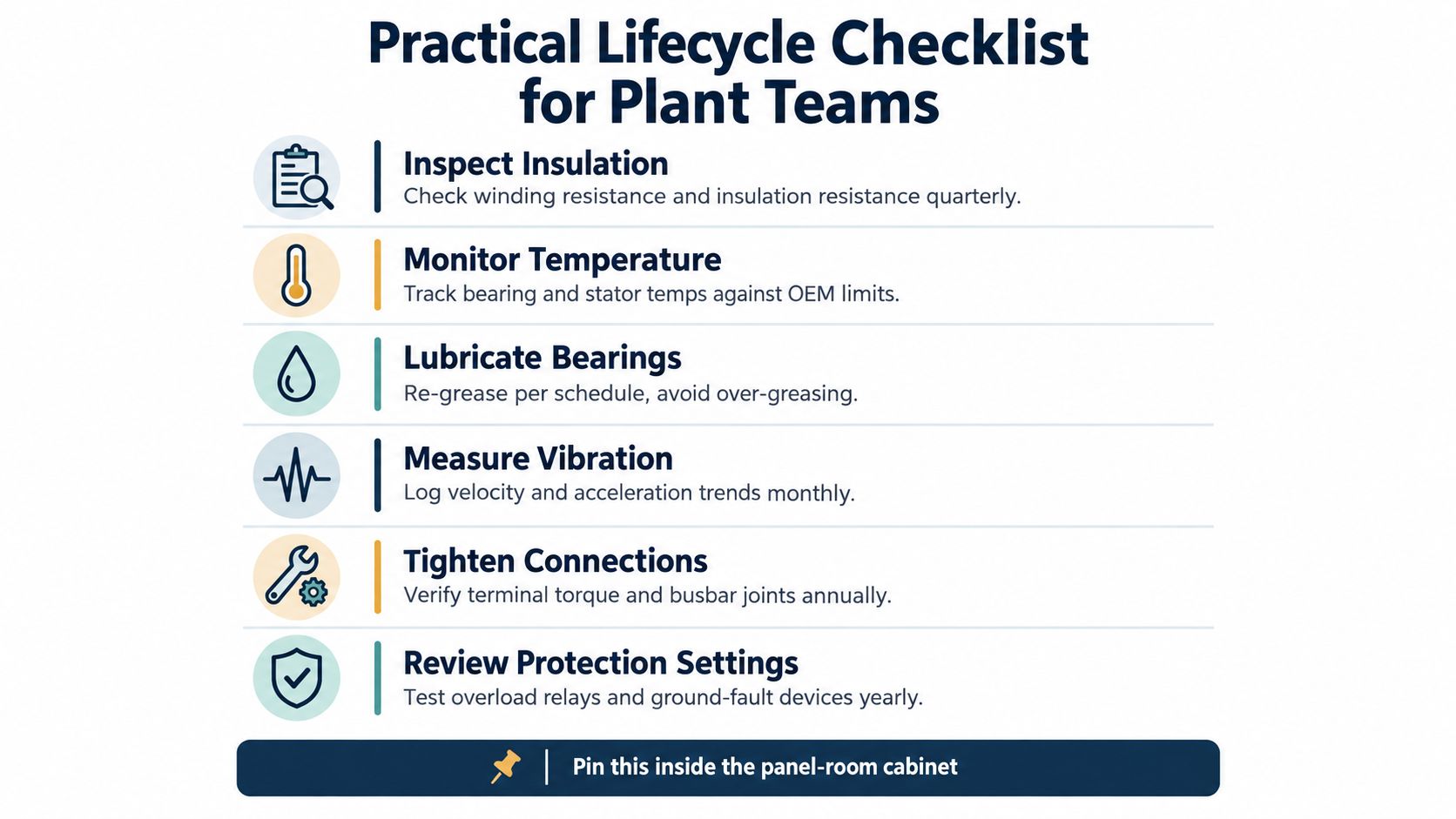
A Practical Lifecycle Checklist for Plant Teams
Use the checklist as an ownership prompt, not a substitute for site procedures. Assign each task to a named role, record the result, and keep the evidence with the motor and drive history.
- Commissioning baseline: Electrical and reliability teams record motor, drive, load, and operating-condition data.
- PD trend: The electrical team compares readings under consistent test conditions and investigates meaningful changes.
- Trip review: The drive owner reviews event logs before approving any restart.
- Environment inspection: Maintenance checks contamination, cooling paths, and enclosure condition against site exposure.
- Restart verification: The responsible supervisor confirms isolation, discharge, fault review, and test conditions.
- Reconditioning trigger: The asset owner compares repair, on-site renewal, workshop work, and replacement using condition evidence and shutdown constraints.
The mindset shift is simple: manage the motor and drive as a coupled system, and replace only what the evidence says needs replacing.
DUCHENG Industrial provides commissioning support, troubleshooting, repair, preventive maintenance, and on-site reconditioning for industrial VFD systems, including medium- and high-voltage equipment. If a recurring trip, constrained shutdown, or aging drive is complicating your motor's restart or renewal decision, visit DUCHENG Industrial to discuss a condition-led service approach.