
A practical medium voltage drive guide covering core concepts, applications, lifecycle challenges, and how lifecycle services reduce downtime and extend asset
At 2 a.m., a maintenance supervisor walks onto the plant floor and sees the unmistakable result of an MV-drive trip. The induced-draft fan is slowing, the motor is still hot, operators are calling from the control room, and production is already moving outside its normal operating envelope. The electrical team can reset the fault, but nobody should press that button until they understand why the drive stopped.
The immediate question is not whether the drive can be repaired. It's whether the fault is inside the power section, the motor, the process, the cooling system, or the plant supply. Then comes the decision that often determines the downtime: should the drive be reconditioned in the substation, or removed and shipped to a specialist workshop?
A medium voltage drive is an engineered system, but it's also a long-life industrial asset. Its availability depends on the quality of commissioning handover, the depth of fault records, the condition of aging components, the compatibility of spare parts, and the repair plan prepared before the trip. The following guide focuses on those decisions, not just the specification sheet.
Table of Contents
- The Moment an MV Drive Goes Dark
- What a Medium Voltage Drive Is
- Inside the Cabinet and Why It Matters for Maintenance
- Where Medium Voltage Drives Earn Their Keep
- Harmonics, Power Quality, and Drive Security
- A Practical Guide to MV Drive Lifecycle Stages
- On-Site Reconditioning Versus Shipping to a Workshop
- Bringing It All Together for Lower Downtime
The Moment an MV Drive Goes Dark
A large induced-draft fan rarely gets a graceful failure. The drive trips, the fan coasts, process temperatures change, and the operations team wants an answer before the alarm history is fully downloaded. The first person at the cabinet often has incomplete information: a fault code, a few trend traces, and an operator report that the motor had been “running normally.”
That description doesn't prove much. A drive can trip because of a failed power cell, degraded insulation, loss of cooling, an unstable control signal, an upstream power-quality event, or a mechanical problem that appears electrically as overcurrent. Resetting without preserving the evidence can erase the most useful clues.
Start with evidence, not a reset
The first response should be controlled and deliberate:
- Secure the equipment: Follow the site isolation procedure, verify the absence of hazardous energy, and respect the medium-voltage arc-flash boundary.
- Save the record: Download the fault history, traceback data, operating values, and event timestamps before changing parameters or cycling control power.
- Check the process: Confirm whether the fan, pump, compressor, mill, or conveyor can be held safely, bypassed, or operated at a reduced process rate.
- Separate symptoms: A drive overcurrent alarm may originate in the motor, driven equipment, cable, tuning, or power electronics.
- Call the right specialist: Give the service team the drive model, fault files, operating conditions, recent work history, and photographs of the cabinet and cooling path.
Practical rule: The first successful restart isn't proof that the fault is gone. It may only prove that the fault condition has temporarily cleared.
The next decision is usually made under pressure. If the failure is localized and the cabinet is accessible, on-site reconditioning may restore operation without disturbing the installation. If several subsystems show heat damage, contamination, insulation stress, or obsolete controls, a workshop rebuild may provide better diagnostic depth. The right answer depends on failure depth, site capability, bypass options, transport constraints, and the cost of leaving the process uncontrolled.
A reliability manager who has already documented those conditions can make the decision quickly. One who hasn't may lose hours debating whether to ship a cabinet before anyone knows which part failed.
What a Medium Voltage Drive Is
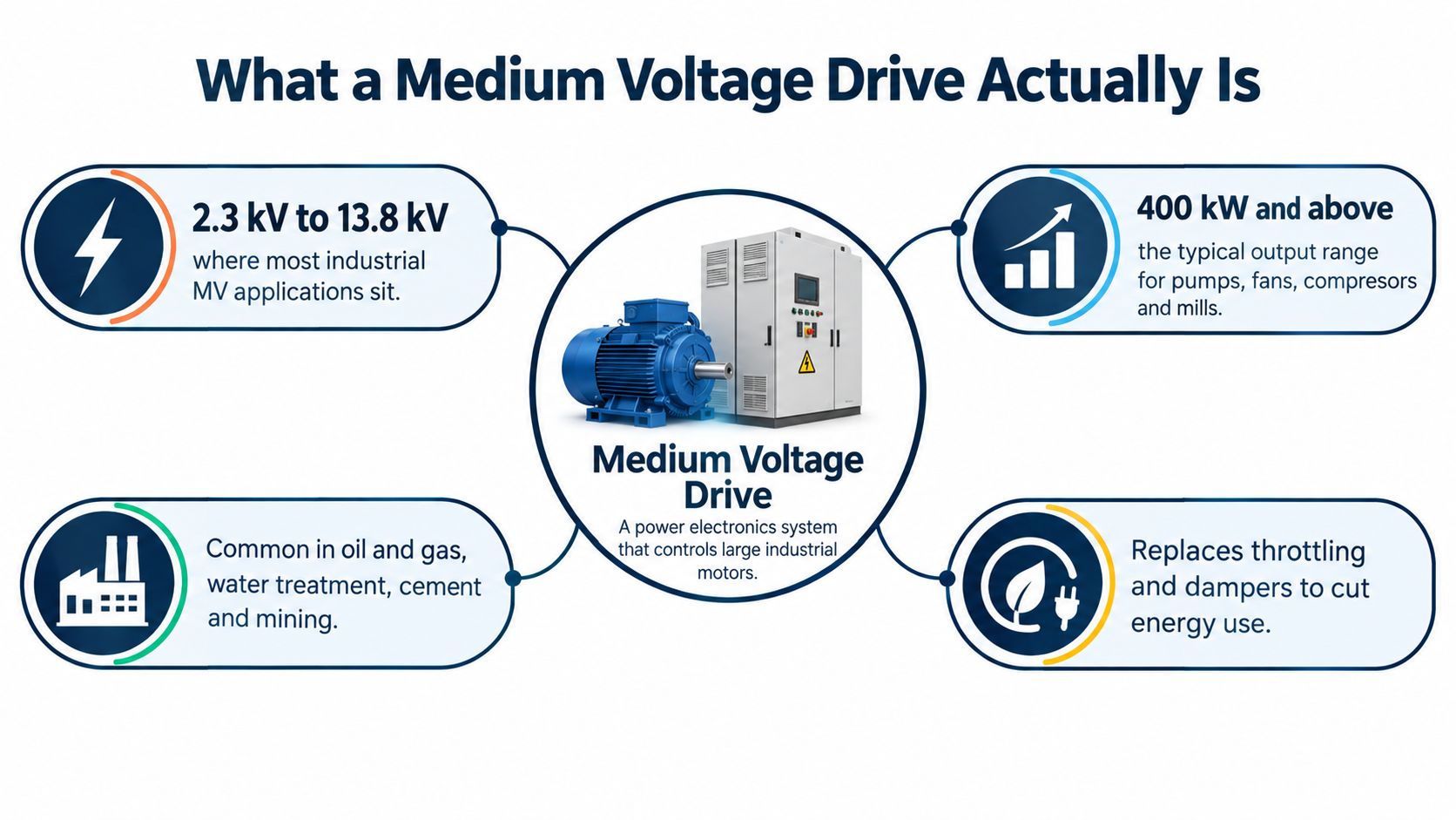
In field terms, a medium voltage drive is a power-electronics system that converts incoming electrical power into controlled voltage and frequency for a large motor. The practical range is narrower than the broad definition of medium voltage. Industrial MV drives commonly operate around 2.3 to 15 kV. 2.3 kV and 4.16 kV are common in the Americas, while 3.3 kV and 6.6 kV are widely used in Europe and other 50-Hz markets, as described in this medium-voltage drive engineering overview.
The drive supplies controlled voltage to the motor. Incoming plant power may pass through an input transformer, line reactor, or another interface before reaching the conversion stages. That arrangement matters during fault work. The motor circuit, drive input, transformer, and plant distribution system have different insulation, protection, and measurement requirements, so a fault indication does not identify the failed component by itself.
Why the motor size changes the decision
The choice between a low-voltage and medium-voltage drive is usually economic and practical. As motor power rises, low-voltage equipment requires higher current, larger conductors, more substantial switchgear, and often larger transformers. MV operation transfers the same power at substantially lower current, which can change cable, switchgear, and installation requirements.
Industrial practice generally makes MV drives attractive above roughly 375 to 750 kW, or approximately 503 to 1,006 horsepower. The boundary varies with cable length, motor voltage, installation cost, fault level, and local design standards. A commercial 4.16 kV drive, for example, can be specified for motors up to 2,500 horsepower, approximately 1.86 MW, while other equipment covers input ranges from 2.4 to 13.8 kV. These figures and the application boundary follow the selection guidance cited above.
That rating decision also affects lifecycle work. A higher-voltage installation may reduce conductor and current requirements, but it demands appropriate insulation testing, isolation procedures, protection coordination, and trained service capability. Those requirements should be captured during commissioning handover, not discovered during the first major fault.
Inside the cabinet, the drive normally rectifies alternating current into a DC link, then uses switching devices to invert that DC into variable-frequency, variable-voltage AC. Voltage-source inverter arrangements use controlled DC voltage, while current-source inverter and load-commutated arrangements control current for suitable motor and process conditions. The result is controlled speed and torque, soft starting, and process adjustment without relying only on throttling, dampers, or mechanical control.
Inside the Cabinet and Why It Matters for Maintenance
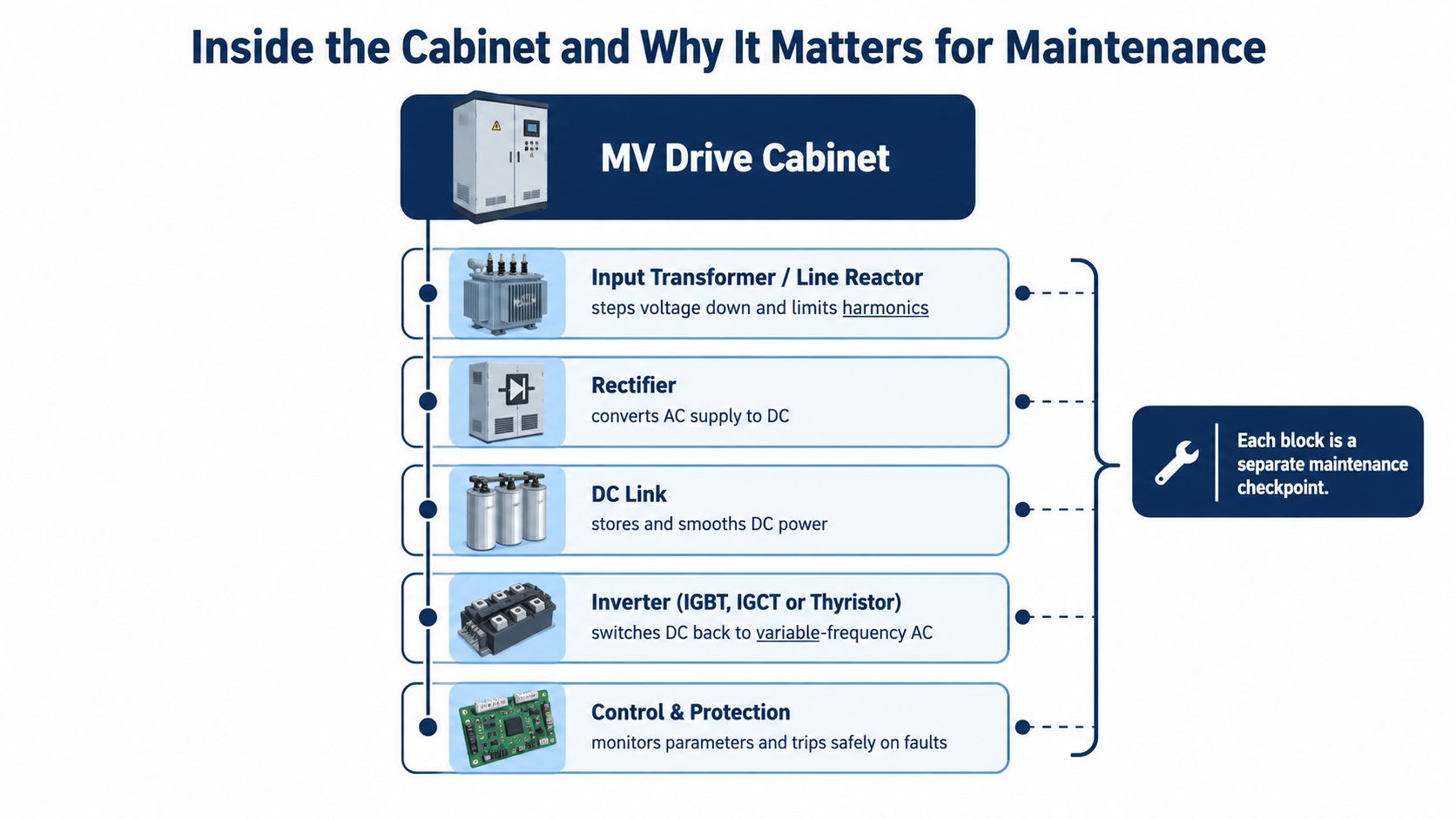
The cabinet is easier to maintain when the team sees it as a chain of functional blocks rather than one sealed product. A typical arrangement includes the input transformer or line reactor, rectifier, DC link, inverter, control and protection electronics, and a cooling system. Each block has a different failure pattern, test method, and spare-parts requirement.
Trace the power path
The input transformer or line reactor adapts the electrical interface and helps manage current waveform behavior. Maintenance staff should inspect connections, temperature rise, insulation condition, phase balance, and signs of overheating. In a plant with multiple converters, transformer performance and upstream impedance also influence power quality.
The rectifier changes AC into DC. Diode, thyristor, or other rectifier arrangements have different test procedures, but a recurring field mistake is to treat an input fault as an isolated drive problem. Check fuses, bridge condition, incoming voltage, phase sequence, and current balance before replacing a power module.
The DC link stores and smooths energy. Capacitors age, drift, leak, and lose usable performance, especially where heat, contamination, or long idle periods are present. A capacitor bank that looks acceptable during a visual inspection may still show abnormal ripple current, unequal voltage, or rising temperature. Capacitor health should be part of the spare-parts and outage plan, not an afterthought following a trip.
Find the failure boundary
The inverter switches DC back into controlled AC through power devices such as IGBTs, IGCTs, or thyristors, depending on the drive architecture. Gate drivers, fiber-optic links, snubbers, fuses, and power-cell interfaces can fail even when the main switching devices appear intact. A control board may also age faster than the power section because it is exposed to heat, vibration, dust, humidity, and repeated power cycling.
Cooling deserves its own inspection route. Air-cooled cabinets collect dust in filters, heat sinks, and ductwork. Water-cooled systems add pumps, heat exchangers, flow switches, hoses, and water-quality concerns. Oil-cooled designs introduce another set of cleanliness, leakage, and thermal-monitoring requirements. A clogged path can turn a marginal component into a trip during peak load.
Maintenance insight: Identify the failed subsystem before choosing the repair location. A replaceable power stack and a contaminated cabinet with aging control electronics are not the same job.
For carbon-black, cement, steel, and other contamination-heavy environments, the internal cleaning method matters as much as the replacement part. A repair that swaps a board but leaves conductive dust in the cabinet can create a repeat outage. A useful maintenance reference for contamination-sensitive applications is this guide to carbon black and MV drives.
Where Medium Voltage Drives Earn Their Keep
MV drives earn their place where a large motor needs controlled speed, controlled starting, or process coordination, and where a low-voltage installation would impose excessive current and infrastructure cost. The most common applications are not interchangeable. A fan, mill, pump, and conveyor impose different acceleration, torque, regenerative, cooling, and mechanical-coupling demands.
The application pattern is clearer than any generic industry label:
| Industry | Typical load | Motor power range | Why MV drive |
|---|---|---|---|
| Cement | Induced-draft fans, kiln drives, raw mills | Large motor and multi-megawatt duties | Controls airflow and process rate while reducing reliance on dampers and mechanical throttling |
| Mining | Slurry pumps, mills, conveyors | Large motor duties across distributed systems | Coordinates torque, limits mechanical shock, and supports controlled material movement |
| Steel | Exhausters, blowers, coilers | High-power continuous and variable-load service | Matches speed to furnace, ventilation, and line requirements while managing demanding starts |
| Water | Raw-water and high-service pumps | Large pump motor duties | Adjusts flow and pressure without forcing the pump to run at one fixed speed |
| Power generation | Boiler-feed pumps, forced-draft and induced-draft fans | Large auxiliary motor duties | Supports stable combustion airflow and controlled pump operation |
A cement plant may prioritize smooth acceleration for a kiln-related load, while a long conveyor system may need master and follower coordination so several motors share torque. A mine may care more about controlled ramping and mechanical protection on a conveyor or pump. A water utility typically values stable pressure and flow control, whereas a thermal power station must protect boiler airflow and auxiliary systems.
Match the drive to the load
The drive rating must reflect more than motor nameplate power. Review starting torque, acceleration time, minimum speed, overload duty, braking requirements, harmonic impact, ambient conditions, motor cable length, and the consequences of a failed cooling system. A fan that normally runs at a stable load can behave differently from a mill with repeated torque disturbances.
For a large conveyor, the control system also matters. Speed mismatch between coordinated drives can create oscillation, uneven load sharing, or recurring overcurrent faults. The maintenance team needs synchronized trends for output current, output voltage, speed reference, actual speed, and process load. Without those records, the team can spend time replacing electrical parts when the actual fault sits in tuning, pulleys, gearboxes, or the belt system.
The economic dividing line is not an absolute technical limit. It reflects the combined cost of current, cabling, switchgear, transformer capacity, motor voltage, and process control. That's why the same plant may use low-voltage drives on smaller auxiliaries and MV drives on the main process loads.
Harmonics, Power Quality, and Drive Security
A drive can operate correctly at its terminals and still create problems elsewhere in the plant. Harmonic current moves through the electrical system, interacts with transformers and capacitors, and can contribute to voltage distortion at the point of common coupling, or PCC. For that reason, commissioning acceptance should measure the installation, not just read a value from the drive keypad.
IEEE 1566 provides a performance framework for adjustable-speed-drive applications above 375 kW, while IEEE 519 is commonly used to assess harmonic generation at the PCC. The IEEE medium-voltage drive guidance explains why transformer impedance, upstream short-circuit strength, parallel loads, and rectifier topology all affect the result.
Compliance is an installation question
A six-pulse rectifier often needs additional mitigation such as line reactors, passive filters, active filters, or an active-front-end converter. Multipulse arrangements use phase-shifted rectifier bridges to cancel characteristic low-order harmonics. An 18-pulse diode rectifier has been reported to meet IEEE 519 requirements in a study case, but that result shouldn't be treated as a universal guarantee for every plant.
A 36-pulse diode architecture is another practical option for large pumps, fans, compressors, mills, and conveyors. One commercial catalogue for a 2 to 36 MW drive specifies input power factor above 0.96, IEEE 519 and IEC 61000-2-4 compliance, and operation across approximately plus or minus 10% input-voltage variation without derating. Larger voltage excursions require derating, and actual field performance still depends on transformer connections, rectifier fuses, cooling, DC-link condition, and load combination, as documented in this medium-voltage drive catalogue.
| Standard | Scope | MV drive implication |
|---|---|---|
| IEEE 519 | Harmonic control at the electrical installation boundary | Measure at the PCC under representative plant loading |
| IEEE 1566 | Performance framework for adjustable-speed drives | Use defined performance expectations during specification and acceptance |
| IEEE 141 | Industrial power distribution design practice | Coordinate the drive with transformers, distribution equipment, grounding, and protection |
| IEC 62443 | Industrial automation and control-system cybersecurity | Treat network access, credentials, changes, and recovery as lifecycle controls |
Treat connectivity as another maintenance boundary
Cybersecurity belongs in the drive handover package because maintenance teams use laptops, removable media, service ports, and remote connections during troubleshooting. The MV-drive cybersecurity guidance recommends practical controls including changing default credentials, enabling parameter write protection, using checksums, restricting physical access to service connections, and disabling unnecessary services and protocols.
The ownership question should be explicit. Electrical maintenance owns safe local access and parameter backups. Controls engineering owns application settings and change control. IT or OT security owns network policy and vulnerability handling. Vendors and service providers need controlled, time-limited access with a recorded purpose and closure check.
Power-quality testing and cybersecurity have the same underlying lesson. A product label or connected feature doesn't replace site verification. Measure distortion at the PCC under representative loading, preserve the baseline, restrict who can change parameters, and test that the plant can restore a known-good configuration.
A Practical Guide to MV Drive Lifecycle Stages
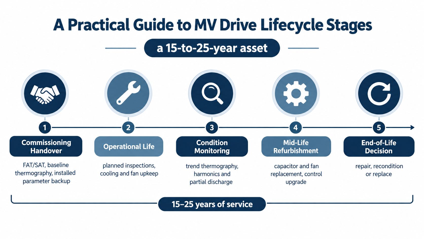
A drive becomes predictable when every stage leaves evidence for the next team. Commissioning shouldn't end with a motor rotation check and a signed punch list. The handover should give maintenance staff the information they need to diagnose a trip years later, when the original project team has moved on.
Build the record at commissioning
Record the installed parameters, motor data, protection settings, control logic, cable and transformer information, cooling arrangement, and approved restart sequence. Keep the original files offline as well as in the plant document system. Capture baseline thermography, current balance, voltage behavior, vibration, and relevant PCC power-quality measurements under representative operation.
Factory acceptance testing and site acceptance testing should connect to the same checklist. If the FAT proves a function that nobody checks during SAT, the handover has a gap. If SAT changes a parameter without preserving the final file, the plant has lost its recovery reference.
Maintain the parts that age
Preventive maintenance should combine visual inspection with electrical and thermal evidence:
- Inspect the power path: Look for loose connections, discoloration, fuse stress, insulation damage, and abnormal phase behavior.
- Check the cooling system: Clean filters and heat exchangers, verify fans or pumps, and confirm flow and temperature alarms.
- Review capacitors: Trend condition indicators and investigate ripple, leakage, swelling, unequal voltage, or rising temperature.
- Protect the control layer: Inspect fiber links, control supplies, boards, connectors, parameter storage, and service-port security.
- Review the fault history: Repeated trips in the same operating region deserve root-cause work, not repeated resets.
Condition monitoring should match the failure modes. Trend cabinet temperature, vibration, harmonic behavior, motor and cable insulation indicators, and controller alarms where the equipment supports them. Partial-discharge testing can help assess cable and motor insulation, while synchronized electrical trends can reveal whether a problem follows process load, speed, or plant operating mode.
Decide before the emergency
After a fault, preserve the evidence, isolate the failed boundary, and decide whether the team needs component replacement, power-stack rebuilding, control refurbishment, or broader reconditioning. A temporary bypass can protect production, but it can also conceal a developing problem if the permanent repair is deferred without a defined risk review.
The upgrade-or-replace decision should consider spare-part compatibility, control-system obsolescence, repeated failures, cybersecurity limitations, and the condition of the motor, transformer, cables, and switchgear around the drive. Replacing a drive doesn't correct a failing cooling system or an unstable supply. Conversely, keeping an obsolete platform without tested parts or a recovery plan can turn a manageable failure into a prolonged outage.
Reliability principle: The most useful lifecycle file is not a purchase order. It's a living record of what failed, what was replaced, what was measured, and what the next technician should verify.
On-Site Reconditioning Versus Shipping to a Workshop
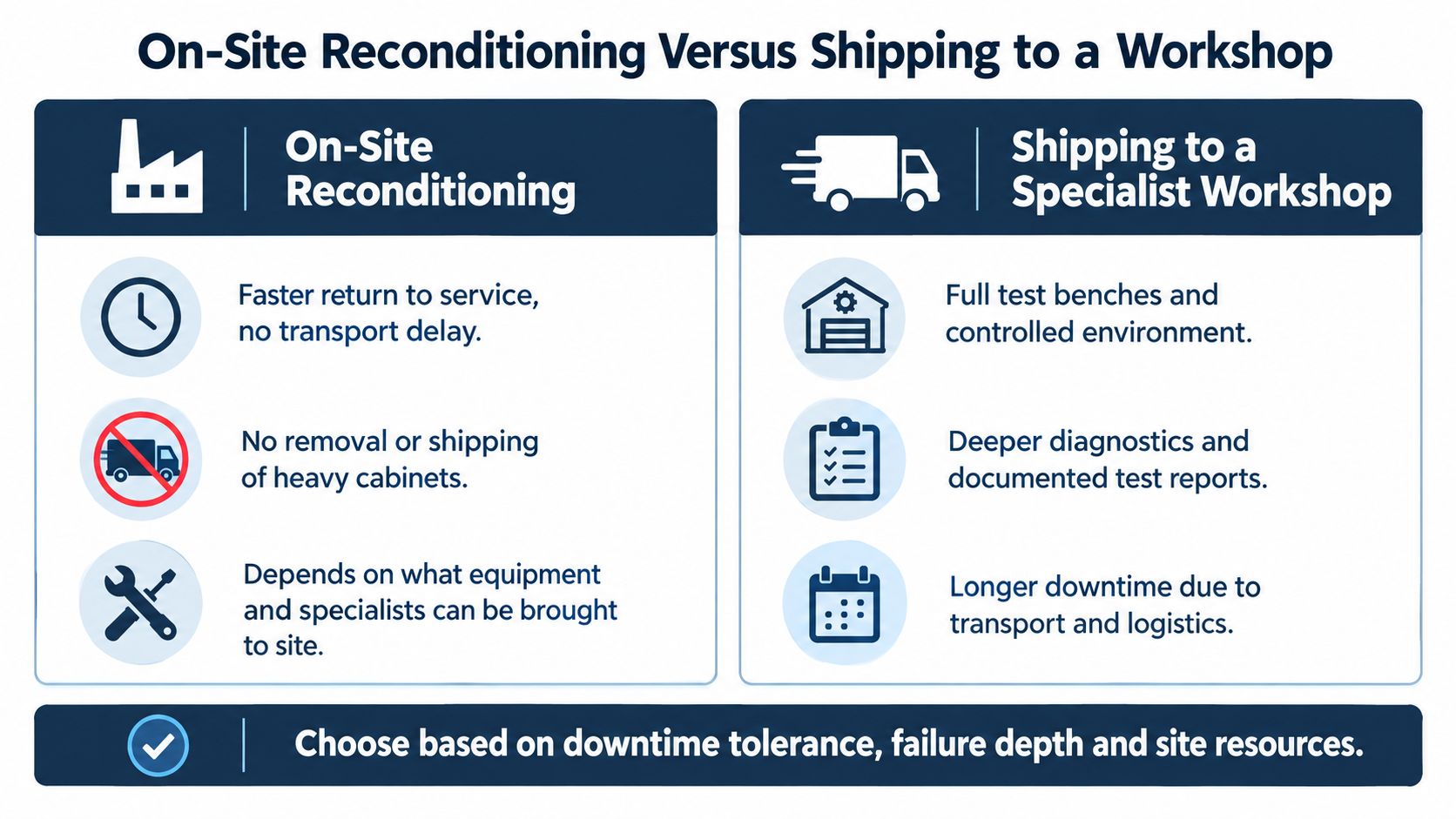
When a medium voltage drive fails, the repair location becomes part of the technical diagnosis. Shipping to a workshop offers controlled conditions, specialist test benches, deeper disassembly, and more room for documented component-level repair. It also introduces cabinet removal, rigging, transport, permits, handling risk, and a longer period without the original equipment in its installed environment.
On-site reconditioning has the opposite profile. Technicians work inside the customer's substation, isolate the failure, clean the cabinet, inspect power cells and control assemblies, replace failed components, test insulation and control functions, and perform a controlled recommissioning. This approach avoids transport damage and can reduce the time between failure identification and return to service, but it depends on the site's safety conditions, access, contamination level, lifting arrangements, and the specialist equipment brought to the job.
Use the failure depth as the decision filter
On-site work is usually attractive when the failure is localized, the cabinet can be safely accessed, the platform remains supportable, and production cannot tolerate extended logistics. It's also useful for legacy fleets where a compatible exchange power cell, gate driver, fan, or fiber board can be identified and verified before installation.
Workshop repair becomes more compelling when the cabinet has extensive contamination, multiple failed subsystems, evidence of heat damage, or a control platform that needs extensive bench testing. It may also be preferable when the site lacks suitable lifting, test, environmental, or high-voltage safety resources.
| Decision factor | On-site reconditioning | Specialist workshop |
|---|---|---|
| Failure scope | Best suited to localized or clearly isolated faults | Better suited to systemic or multi-subsystem damage |
| Downtime exposure | Avoids removal and transport steps | Includes logistics and workshop scheduling |
| Test environment | Depends on site conditions and portable equipment | Offers controlled benches and documented test sequences |
| Contamination | Can be handled where the cabinet is installed | Allows deeper cleaning and disassembly |
| Legacy equipment | Useful when field compatibility checks are available | Useful for extensive reverse engineering and bench diagnosis |
| Documentation | Must be built carefully during field work | Usually supports detailed workshop test records |
The first question should be, “What do we know about the failed boundary?” The second should be, “What must be proven before energization?” That prevents a fast field repair from becoming an uncontrolled restart, and it prevents a workshop shipment from becoming an automatic response to every trip.
A multi-brand fleet makes compatibility especially important. A visually similar board or power cell isn't automatically interchangeable. Confirm firmware, ratings, gate-drive behavior, fiber interfaces, cooling requirements, protection settings, and revision status. For a broader view of structured VFD repair services, the same principle applies: diagnose first, match the repair method to the failure, and verify the complete drive before return to production.
A repair video can help supervisors understand the difference between component replacement and broader refurbishment, but it shouldn't replace site-specific isolation, test, and commissioning procedures.
<iframe width="100%" style="aspect-ratio: 16 / 9;" src="https://www.youtube.com/embed/0xBo51QBd-8" frameborder="0" allow="autoplay; encrypted-media" allowfullscreen></iframe>Bringing It All Together for Lower Downtime
An MV drive behaves like a long-life rotating asset even though its failure modes are electrical. Availability is decided over years by the quality of records, inspection routines, spare-parts choices, repair methods, and operating discipline. The trip event only exposes the consequences of those earlier decisions.
Four principles work across heavy industrial sites:
- Instrument the drive at handover. Preserve the installed parameter set, baseline temperatures, operating values, protection settings, and power-quality evidence. A technician can troubleshoot a trend. A technician cannot troubleshoot a missing history.
- Standardize spares around actual failure modes. Keep the parts that the fleet needs, verify compatibility across revisions, and store sensitive components under controlled conditions. A shelf full of unverified boards isn't resilience.
- Choose the repair location by failure type. Localized power-cell or control faults may suit on-site reconditioning. Systemic damage, deep contamination, or extensive bench diagnosis may justify workshop work.
- Manage the fleet, not just the individual drive. Group assets by platform, voltage, application, control revision, cooling arrangement, and spare-parts compatibility. This makes obsolescence visible before it becomes an emergency.
A structured service program can combine commissioning support, preventive inspections, emergency diagnosis, workshop repair, on-site reconditioning, spare-part identification, and upgrade assessment. It can also define who owns the parameter backup, who approves remote access, who signs off a restart, and who decides whether a legacy platform remains serviceable.
DUCHENG Industrial provides multi-brand commissioning, maintenance, troubleshooting, workshop repair, on-site reconditioning, spare-parts compatibility review, and upgrade or replacement assessments for industrial VFD assets. For a plant team, that kind of lifecycle coverage is useful when the priority is not just to replace a failed component, but to restore a controlled and documented operating condition.
The objective is straightforward: reduce the time needed to isolate a fault, avoid unnecessary cabinet transport, prevent repeat failures, and make capital replacement a planned decision rather than a reaction to a preventable outage. A drive that has a clear service history, tested spares, secure access, and a defined repair path is far easier to budget and far less likely to decide the night's production schedule by itself.
If your plant relies on medium-voltage drives, DUCHENG Industrial can help assess the installed fleet, diagnose faults, perform on-site reconditioning, and determine whether repair, upgrade, or replacement is the sensible next step. Contact the team through DUCHENG Industrial to plan a practical lifecycle service approach around your critical drives.