
Learn how medium voltage motors stay reliable in 2026: maintenance schedules, common failure causes, testing tips, and uptime practices for industrial plants.
Medium voltage motors commonly run at 3.3 kV, 6.6 kV, or 11 kV, and that higher voltage cuts current sharply for the same output. In one common comparison, a 1 MW three-phase motor draws about 87 A at 6.6 kV versus about 1,253 A at 460 V, which is why these machines can use smaller conductors and lower-loss power paths in heavy industry (IEEE-oriented classification and industrial ranges).
That simple current reduction is only part of the story. Once a motor lives in the medium-voltage world, insulation condition, partial discharge, grounding, switching equipment, and restart behavior become everyday reliability problems, not occasional edge cases (IEEE-oriented classification and industrial ranges).
Table of Contents
- Why Medium Voltage Motors Demand a Different Maintenance Mindset
- Insulation Stress and the Hidden Failure Paths in High-Voltage Windings
- Starting Stress, Locked-Rotor Current, and Protection Coordination Reality
- Variable Frequency Drive Compatibility and Energy Savings With Real Limits
- Failure Mode Analysis and Case-Oriented Reliability Decisions
- Reconditioning Versus Replacement and the Lifecycle Cost Reality
Why Medium Voltage Motors Demand a Different Maintenance Mindset
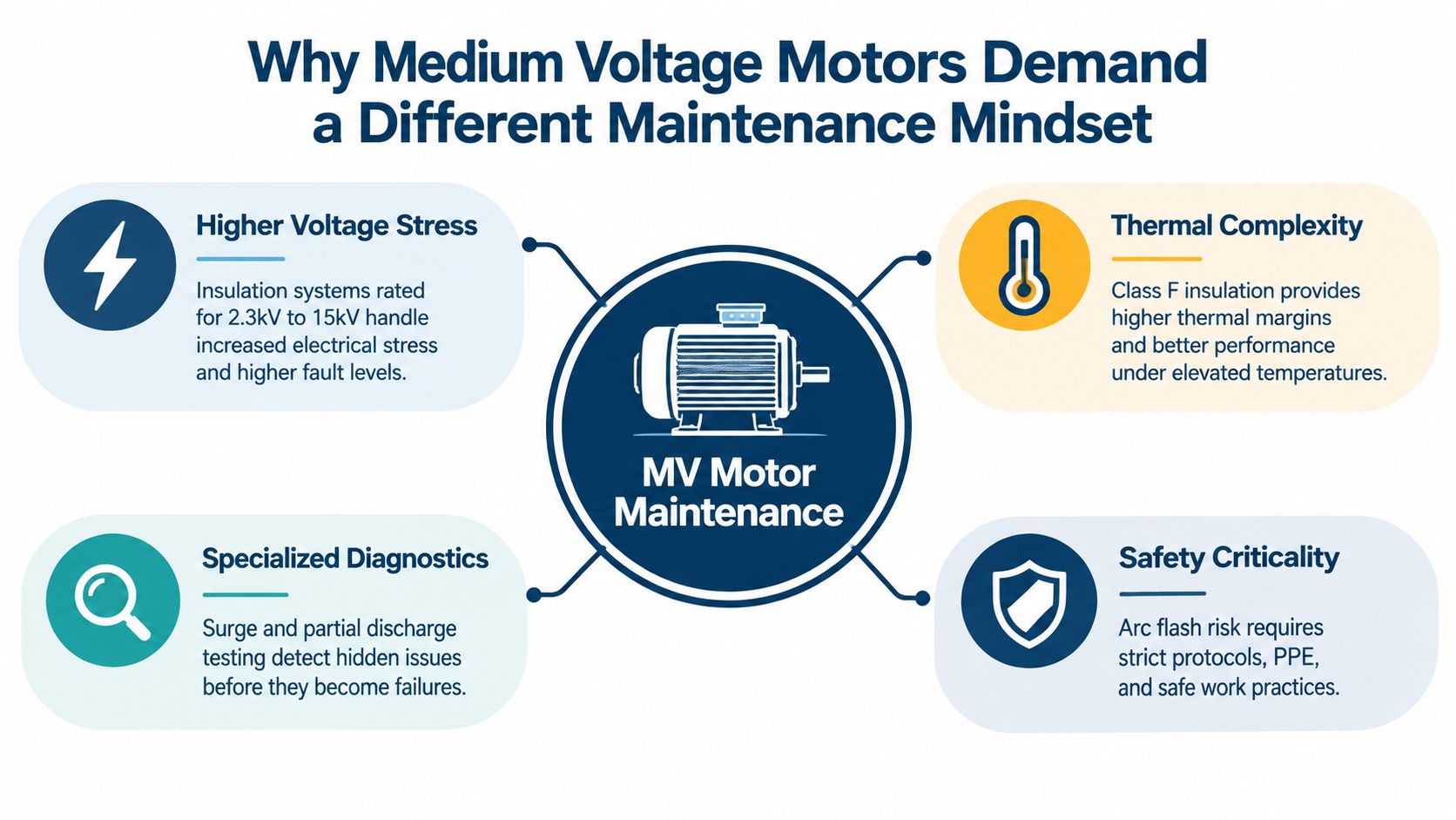
Medium voltage motors don't fail like small plant motors, and they shouldn't be maintained like them either. They sit in a voltage class that runs roughly from 1 kV to 36 kV in IEEE-oriented practice, with IEC usage extending above 1 kV to around 52 kV, and that changes the whole maintenance burden (IEEE-oriented classification and industrial ranges). In real plants, the equipment is often fed at 3.3 kV, 6.6 kV, 11 kV, or 13.8 kV, which puts electrical stress directly into the winding system and the switchgear around it (IEEE-oriented classification and industrial ranges).
What changes above one kilovolt
The first mistake teams make is thinking the only difference is size. A medium voltage machine serves large pumps, compressors, fans, conveyors, crushers, and rolling equipment, where current reduction is the point of choosing that voltage class in the first place (IEEE-oriented classification and industrial ranges). That means a maintenance program has to care about the whole electrical path, not just bearings and alignment.
Practical rule: if the asset can interrupt an entire production train, treat insulation and restart integrity as first-class maintenance items, not add-ons.
In these systems, electrical stress ages the winding long before a casual visual inspection shows trouble. The motor can look mechanically sound and still be one bad partial-discharge trend away from a forced outage (IEEE-oriented classification and industrial ranges).
Why the old low-voltage routine falls short
Low-voltage habits usually overemphasize grease, vibration, and temperature while underweighting insulation behavior. That works until a medium voltage winding begins to degrade internally, because the useful warning signs are often electrical rather than visible. A routine that catches looseness on a 400 V motor can miss early defect growth in a 6.6 kV machine.
The operating context matters too. Medium voltage motors are common in mining, steel, cement, oil and gas, petrochemicals, pulp and paper, power generation, and water treatment, where process continuity matters more than convenience (IEEE-oriented classification and industrial ranges). For those sites, a “run it until it trips” mindset is usually the most expensive maintenance strategy on the floor.
Insulation Stress and the Hidden Failure Paths in High-Voltage Windings
Insulation in a medium voltage motor doesn't usually fail in one dramatic event. It deteriorates through electrical stress, heat, and repeated mechanical movement, then gives up when enough small defects line up. The useful question isn't whether the winding is still running today, it's whether the trend says the insulation is still stable enough for the next production cycle.
Partial discharge starts the slow damage
Partial discharge is localized electrical activity inside or near defects, voids, interfaces, or high-field regions in the insulation system (IEEE Atlanta MV Motor Designs and Standards presentation). Repeated activity erodes the insulation, and over time that can turn into turn-to-ground or phase-to-phase failure (IEEE Atlanta MV Motor Designs and Standards presentation). One technical reference specifically notes 6.9 kV insulation systems requiring corona-control measures such as corona tape, which tells you how seriously winding design has to manage field concentration at this voltage level (IEEE Atlanta MV Motor Designs and Standards presentation).
A good maintenance program doesn't stop at insulation resistance. That test is useful for gross moisture or contamination, but it can miss the kind of localized deterioration that later becomes a shutdown event (IEEE Atlanta MV Motor Designs and Standards presentation).
A winding can pass one simple test and still be in real trouble. Trending matters more than a one-time pass/fail result.
Corona control and manufacturing quality matter
Corona-control materials, vacuum-pressure impregnation, and void-free construction are not brochure features, they're damage prevention measures (IEEE Atlanta MV Motor Designs and Standards presentation). The reason is straightforward, any void or interface becomes a place where stress can concentrate and partial discharge can start. Once that starts, the insulation doesn't recover just because the motor is dry again.
A practical condition program should trend polarization index, winding resistance, surge-test results where appropriate, and offline or online partial-discharge measurements under comparable conditions (IEEE Atlanta MV Motor Designs and Standards presentation). The reason to trend is simple, rising defect magnitude and changing phase-resolved patterns tell you more than a single reading ever will.
VFD supply changes the insulation risk
When the motor is fed from a variable-frequency drive, the insulation sees more than a clean sine wave. Repetitive switching impulses, cable reflections, common-mode voltage, and grounding effects can raise local electrical stress beyond utility supply conditions (IEEE Atlanta MV Motor Designs and Standards presentation). That's why a motor that behaved well on line power can age faster after a drive retrofit if the insulation system and grounding path weren't reviewed together.
The practical move is to look for movement in the data, then tie that movement to action. Clean the motor if the issue is contamination, but don't pretend every alarm is reversible. When the trend points to irreversible deterioration, schedule the work before the failure decides the timing for you.
Starting Stress, Locked-Rotor Current, and Protection Coordination Reality
Medium voltage induction motors can draw locked-rotor current up to about 8.0 per-unit of full-load current at standstill (locked-rotor current and starting guidance). That happens because the rotor isn't yet generating counter-electromotive force, so the stator sees a very low effective impedance (locked-rotor current and starting guidance). The result is a hard electrical hit on the supply and a thermal hit on the motor before the load even begins to move.
What that starting current does to the plant
The current spike can dip voltage enough to disturb neighboring loads, especially on weaker networks (locked-rotor current and starting guidance). It also forces the motor to live inside its thermal withstand limit while it accelerates, which is why the starting profile matters as much as the full-load rating. High-inertia fans, compressors, mills, and conveyors are the classic traps here, because repeated failed starts can stack thermal damage faster than the machine cools.
Record the actual start current, acceleration time, terminal-voltage dip, and thermal model response during commissioning. That data is what turns protection settings into a real safeguard instead of an optimistic guess.
Protection has to follow the motor, not a rule of thumb
Overload relays need to ride through normal starting, while fuses or circuit breakers still need to clear genuine faults (locked-rotor current and starting guidance). That sounds obvious, but in the field it gets mishandled often. A setting that protects beautifully in steady state can nuisance-trip on the first long acceleration, and a forgiving setting can leave fault energy in the circuit too long.
The safe approach is to base coordination on the manufacturer's locked-rotor current and acceleration time, not on a generic multiplier (locked-rotor current and starting guidance). If the supply network can't tolerate across-the-line starting, use a reduced-voltage method or a medium voltage drive, but only if the selected method still provides enough accelerating torque for the load (locked-rotor current and starting guidance).
A commissioning habit that pays off
The most useful commissioning habit is to verify the start as a measured event. Compare the recorded current and timing against the motor's permissible locked-rotor withstand time, then keep those records with the protection curves. That way, when an operator reports a harder start after process changes or mechanical drag, the evidence is already there.
A start that “seems fine” once doesn't prove the system is healthy. It only proves the protection didn't complain during that one attempt.
Variable Frequency Drive Compatibility and Energy Savings With Real Limits
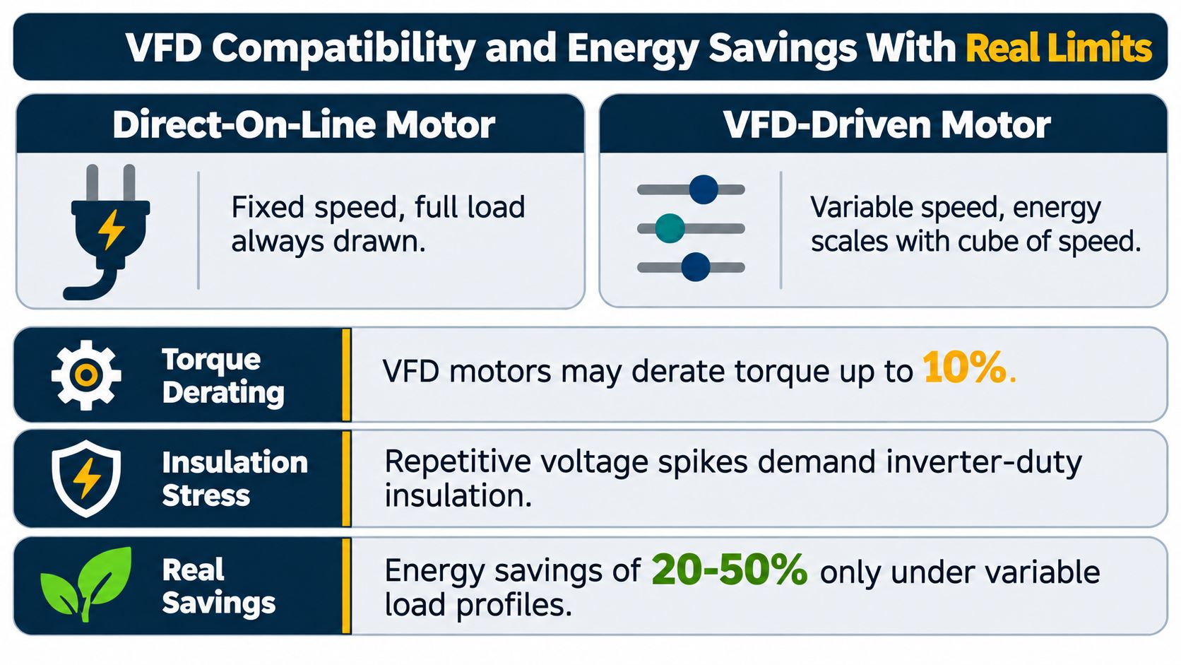
Variable speed control can be a real win on centrifugal pumps and fans because power falls roughly with the cube of speed. As an illustration, reducing speed to 80% can reduce idealized shaft power to about 51.2% of full-speed power before drive and motor losses are included. That relationship is why VFD retrofits get so much attention in industrial energy programs.
Where the gains are real
The best candidates are processes that don't need constant full speed. Induced-draft fans, boiler-feed pumps, compressors, mill drives, and large cooling-water systems are often good fits because the operating point changes with demand. In those cases, variable speed control can improve both energy use and process control.
But the gain depends on duty cycle, system resistance, minimum-flow requirements, motor efficiency, and drive losses. Market literature commonly reports 20–40% energy reduction potential for suitable centrifugal-load applications when fixed-speed operation is replaced with variable-speed control, but that's not automatic for every motor or every process. If the process spends most of its life near full load, the payback story changes.
What VFDs add to the reliability picture
A drive retrofits control into the system, but it also adds new failure paths. Harmonic assessment, cooling, insulation stress management, parameter backup, spare-part strategy, and periodic inspection all become lifecycle tasks because a drive trip can stop a whole train instead of a single motor. The motor itself also needs attention, because repetitive voltage stress can create problems the old line-fed arrangement never saw.
Don't call a retrofit “efficient” until you've checked the whole chain, motor, drive, cooling, harmonics, and the process constraint at minimum flow.
Repair or replace depends on more than efficiency
The next bad habit is assuming a higher efficiency class automatically justifies replacement. IEC 60034-30-1:2025 introduces IE5 and harmonizes efficiency classification, but its testing basis is sinusoidal-voltage operation and its scope centers on line-operated motors (IEC 60034-30-1:2025). That leaves a real gap for VFD-fed medium voltage assets, because nameplate efficiency alone doesn't capture harmonics, converter losses, auxiliary cooling, partial-load duty, repeated starts, or aging drive-motor pairings.
A better decision asks what the operating load looks like, how the temperature history reads, whether insulation is still healthy, and how much outage risk the plant can tolerate. If the drive and motor are both old, the cheapest purchase price may still be the most expensive lifecycle decision.
Failure Mode Analysis and Case-Oriented Reliability Decisions
A steel plant doesn't lose a motor the same way a utility or chemical site does, but the warning pattern is often familiar. The first red flags are usually subtle, repeated trips, rising heat, or a partial-discharge trend that doesn't match the last inspection report. The mistake is treating those signals as isolated nuisances instead of a joined-up failure path.
Case pattern one, the fault that keeps returning
A large fan motor starts tripping after warm days and restarts cleanly after the team resets it. The electrical readings look acceptable at first, so operators assume the issue is transient. Weeks later, the trips become harder to clear, and the underlying problem turns out to be insulation stress combined with thermal buildup.
That pattern is common where online thermal or electrical monitoring is absent. Research on medium voltage arc-fault precursors points to insulation degradation and thermal stress as leading noncontact warning paths, and it also shows how partial-discharge and thermal sensors can feed indicators into protection systems, PLCs, or SCADA (new preemptive arc fault detection techniques in medium voltage systems). The useful move isn't just to alarm, it's to turn the alarm into a decision, derate, inspect, or plan the outage.
Case pattern two, the trip that's really a system issue
A compressor drive trips after a restart, then the motor is suspected first because that's the obvious rotating asset. A closer review shows the fault pattern is tied to the electrical environment and the restart procedure, not just the machine itself. In these situations, recurring faults often point to the broader system, cable condition, cooling, grounding, or the way the process is being started.
If the same fault returns after reset, stop treating it as a one-off. Look for the mechanism that's being asked to survive the same stress again.
The best programs don't separate electrical, thermal, and mechanical observations. They connect them. That means using online monitoring where the process can't tolerate surprise downtime, then pairing the data with planned field diagnostics so contamination, irreversible insulation damage, and mechanical issues don't get blurred together. For teams that need that kind of response path, DUCHENG Industrial provides lifecycle support for medium-voltage drive assets, including on-site diagnosis and controlled recovery of drive-related faults.
Reconditioning Versus Replacement and the Lifecycle Cost Reality
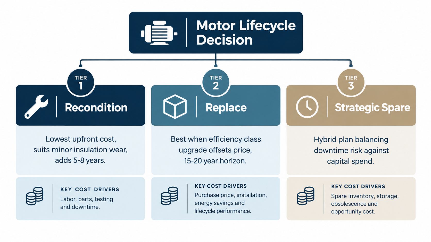
A motor decision gets expensive when teams frame it as “repair or buy new” too early. The core choice is usually between reconditioning, replacement, a drive upgrade, or holding a strategic spare, and each one has a different risk profile. The right answer depends on what the asset is doing today, not just what the nameplate says.
Recondition when the core machine is still worth saving
Reconditioning makes sense when the motor is mechanically sound and the insulation damage is limited enough that refurbishment can restore dependable service. It's the path that usually preserves the most installed fit, especially when the machine is large or removal is difficult. The trade-off is that a cheap repair isn't really cheap if the same failure mechanism returns six months later.
Replace when the lifecycle math starts to bend
Replacement becomes more attractive when the operating environment, parts availability, or motor-drive pairing has moved beyond sensible repair. Industry material cites 6 to 12 months as a typical replacement lead-time range for medium voltage motors, with large synchronous machines sometimes taking longer than 12 months (IEC efficiency classification and MV replacement lead times). That's why replacement decisions can't be made in a panic after a trip. By the time the machine is dead, the calendar is already working against you.
Keep a strategic spare when downtime is costlier than capital
A strategic spare is the middle ground that plant managers often overlook. It balances downtime risk against capital spend, especially where a single outage can halt a critical process train. The key is compatibility, because a spare only helps if the fit, insulation system, protection settings, and restart procedure are already validated.
The smartest spare is the one you can install without improvising on the day of the outage.
A disciplined decision framework looks at load history, temperature trend, insulation condition, fault recurrence, remaining parts availability, and the cost of production downtime. That same logic also supports on-site reconditioning, which DUCHENG Industrial provides for medium-voltage drive assets when shipping a large unit off site would add too much delay and handling risk. For repair planning, the practical reference point is simple, use industrial motor repair guidance to keep the decision tied to diagnostics, not hope.
DUCHENG Industrial supports medium-voltage drive assets with commissioning, troubleshooting, preventive maintenance, workshop repair, and on-site reconditioning, which matters when a trip, insulation concern, or compatibility question can't wait for a long outage window. If your team needs a practical review of whether to recondition, upgrade, or replace, visit DUCHENG Industrial and start with the asset data, not the guesswork.