
Industrial motor repair explained for plant teams. Step-by-step diagnostics, on-site vs shop decisions, parts compatibility, and return-to-service testing.
A pump house at a steel mill loses flow when a large induction motor trips on a ground fault. The drive has locked out, production is waiting, and the maintenance team has a narrow shutdown window to decide whether to pull the motor, send it to a workshop, or recondition it beside the equipment. Every hour spent on the wrong path adds more risk, especially when lifting, alignment, transport, and recommissioning are part of the recovery.
That's the problem in industrial motor repair. The question isn't whether the motor can be repaired or replaced. It's which path minimizes total downtime, transport exposure, and repeat-failure risk for this motor, its duty cycle, and the available shutdown window.
Repair remains a practical choice for many industrial fleets because it preserves a proven mechanical fit and avoids unnecessary changeout work. Historical industry data illustrates the scale of that preference. In the United States, about 2.5 million new motors over 5 horsepower were sold in 1993, while roughly 1.8 million to 2.9 million motors in the same broad class were repaired. Repaired units represented more than 200 million horsepower, compared with 75 million to 100 million horsepower in new sales, according to historical industrial motor repair market data.
The decision still has to start with diagnosis, not disassembly.
Table of Contents
- When a Tripped Motor Forces the Question
- On-Site Repair, Shop Repair, or Replacement
- Field Repair Workflow for LV and MV Motors
- Workshop Deep Repair and Component-Level Work
- Spare Parts, Compatibility, and Pre-Dispatch Checks
- Return-to-Service Testing That Actually Proves It
- Building a Repair Habit That Outlasts the Next Trip
When a Tripped Motor Forces the Question
The first call after a motor trip is often framed as a repair request. The first job should be to establish what happened. A ground-fault trip can come from winding insulation, a damaged cable, a contaminated terminal box, a drive output issue, or a fault that only appears under heat and load.
The shift electrician should preserve the trip code from the drive or soft starter before resetting anything. Record available line-side voltage and current information, note whether the motor was accelerating or running steadily, and ask the operator about unusual noise, smell, vibration, cycling, or recent work. A technician who skips this history may spend hours repairing the symptom while leaving the initiating condition in service.
Diagnose before touching the motor
The initial assessment should follow a deliberate sequence:
- Trip and operating history: Capture the protection event, load condition, recent starts, overloads, cycling, bearing work, and environmental changes.
- Mechanical condition: Check shaft play, coupling condition, bearing noise, signs of rubbing, blocked ventilation, and evidence of water, dust, oil, or process contamination.
- Insulation condition: Measure insulation resistance phase to ground and, where appropriate, polarization behavior. Record temperature and humidity because readings need context.
- Winding integrity: Compare phase resistance and inductance. An imbalance can point toward a connection problem, partial short, or winding damage.
- Turn insulation: Use surge comparison testing when winding damage is suspected. A megohmmeter can miss weaknesses between turns that surge testing can expose.
- Rotor condition: Evaluate squirrel-cage rotor bars and end rings with suitable rotor testing methods when the symptoms suggest broken bars, high slip, or abnormal starting behavior.
- Core condition: Perform core-loss testing when a winding repair is possible. A damaged lamination stack can create a hot spot that compromises a new winding.
This order matters because each result narrows the repair path. A failed bearing may justify a targeted field intervention. A winding fault combined with core damage usually calls for controlled workshop work. A cable or termination defect may mean the motor itself should remain untouched.
Practical rule: A motor shouldn't leave the plant until the team can state the suspected failure mode, the evidence supporting it, and the test that will confirm or reject it.
The diagnostic stack
A repair shop should provide recorded results, not a verbal assurance that the motor “tested fine.” Expert motor-reliability guidance recommends calibrated instruments and documented testing throughout the repair, with a reliability example reporting 90.5% for a well-executed repair versus 5% for a low-quality repair. Those figures come from motor repair reliability guidance, and they reinforce a practical point: quality is built into the test sequence.
| Test | What it detects | When it is mandatory |
|---|---|---|
| Phase resistance and inductance | Open connections, phase imbalance, winding anomalies | Before electrical repair and after reconnection |
| Insulation resistance | Moisture, contamination, and insulation degradation to ground | Before energization and after repair |
| Surge comparison | Turn-to-turn insulation weakness | When winding damage or a rewind is possible |
| Rotor testing | Bar or end-ring defects in squirrel-cage rotors | When starting, torque, or current symptoms point to the rotor |
| Core-loss testing | Localized heating risk in the stator core | Before approving a winding repair |
| Mechanical inspection | Bearing, shaft, fit, coupling, and alignment problems | Every time the motor is opened |
| Loaded run test | Voltage, current, vibration, temperature, and noise behavior | Before final handover |
The motor repair decision becomes much clearer once these results are available. The team can distinguish a component-level fault from a deep electrical failure, and it can judge whether the installed motor is safer to recondition in place than to move through the plant and onto a truck.
On-Site Repair, Shop Repair, or Replacement
Once the fault is understood, choose the repair path against the shutdown window, motor duty, transport risk, and likelihood of repeat failure. On-site work can remove lifting and shipping delays, but it requires contamination control, qualified personnel, and correctly rated test equipment. Workshop repair gives better control for major electrical and mechanical work, while transport adds handling, scheduling, and alignment risks.
| Criterion | On-site reconditioning | Workshop deep repair | Replacement |
|---|---|---|---|
| Localized bearing, fan, terminal, cable, or encoder fault | Strong fit | Usually unnecessary | Rarely justified |
| Medium-voltage winding dry-out or partial repair | Possible with portable equipment and controls | Strong fit for extensive work | Consider after technical review |
| Full stator removal or major rotor work | Poor fit | Preferred | Depends on frame, availability, and failure history |
| Heavy motor that is difficult to move | Reduces transport and lifting risk | Adds logistics and handling | Installation work may still be required |
| Tight shutdown window | Useful when tools and parts are ready | Practical with a verified exchange unit | Practical only with a compatible unit available |
| Obsolete frame or recurring non-warranty failure | Limited value | May not be economical | Rational after failure analysis |
For low-voltage motors, field reconditioning suits bearing replacement, encoder work, terminal-box service, fan replacement, and cleaning. It can also make sense when a motor is heavy, access is difficult, or the shutdown cannot absorb removal and transport. The work still needs controlled disassembly, clean conditions, suitable measurements, and a clear return-to-service decision.
Medium-voltage reconditioning can be performed on-site when the team has controlled drying, insulation treatment, appropriate clearances, and suitable test equipment. That path reduces transport exposure, but it does not reduce the technical standard. If the site cannot control moisture, contamination, lifting, or testing, send the motor to a workshop.
Workshop repair is the safer choice for a stator lift, extensive winding work, shaft restoration, rotor machining, or precision balancing. Replacement becomes reasonable when the frame is obsolete, a compatible unit is available and verified, or failure analysis shows that repair would return the same unresolved design or application problem. A replacement that has not been checked against voltage, frame, shaft, bearings, enclosure, and duty can create a second outage.
Automatic replacement policies deserve scrutiny. Industry triage data found 79% of failed electric motors repairable and 21% replaced, while 49% of repaired units involved mechanical repairs and 30% involved electrical rewinds, as reported in motor maintenance trend data. A bearing, seal, termination, or rotor component may be the actual failure, not a reason to discard the complete motor. The best path is the one that restores the required duty with the lowest total downtime and controlled repeat-failure risk.
Field Repair Workflow for LV and MV Motors
A field repair begins with a safe boundary around the equipment. Lock out electrical sources, release stored energy, verify absence of voltage, control backfeed paths, and account for driven equipment movement. Medium-voltage work needs its own clearance, grounding, arc-flash, and access controls. It shouldn't be treated as a larger version of low-voltage maintenance.
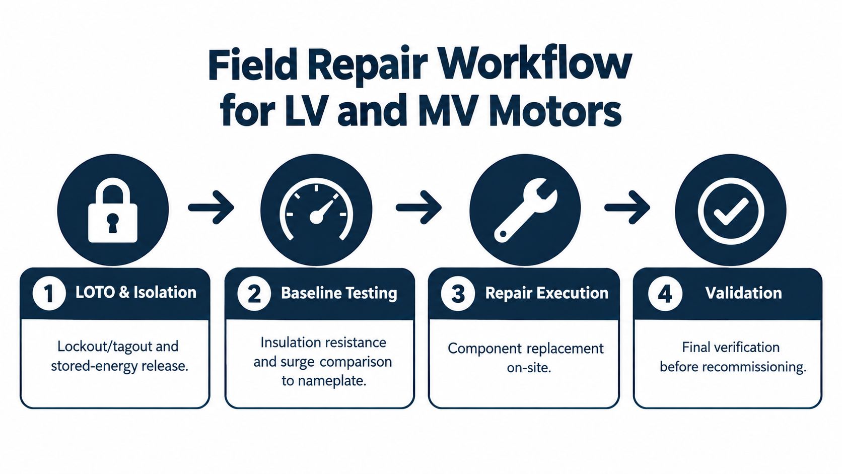
With the motor isolated, establish a baseline before removing covers. Record insulation readings, phase resistance, terminal condition, nameplate information, and any available pre-failure vibration or temperature data. Photograph connections and cable routing. The record should make it possible for another technician to understand the original condition without relying on memory.
Keep contamination out of the repair
Every opened enclosure creates an opportunity for moisture and particulates to enter. Use clean covers, controlled work areas, sealed containers for removed hardware, and lint-free cleaning materials. In dusty, saline, carbon-contaminated, or wet environments, cleaning is part of the electrical repair, not cosmetic preparation.
Component-level interventions should follow the evidence. Bearings may require controlled heating rather than impact installation. Encoder work requires mechanical alignment and confirmation that the feedback device communicates correctly with the drive system. A damaged terminal or cable needs inspection for tracking, looseness, insulation damage, and incorrect torque.
For MV motors, drying and insulation treatment require controlled temperature, ventilation, and test confirmation. If the team cannot maintain those conditions beside the asset, the field path has stopped being the lower-risk option. Record each intervention, the part fitted, the measurement taken, and the acceptance result. The motor-drive repair workflow should produce a traceable technical record, not only a restarted machine.
Validation follows the repair. Repeat the relevant insulation and winding checks, verify connections, confirm rotation direction, and run the motor under controlled conditions. A field repair is complete only when the evidence supports recommissioning and the asset history has been updated.
Workshop Deep Repair and Component-Level Work
A workshop earns its value through control. The motor should arrive with its identity, failure symptoms, test results, and operating history attached. Before disassembly, photograph the assembly, mark orientation, record air gaps and fits where relevant, and preserve damaged components for failure analysis.
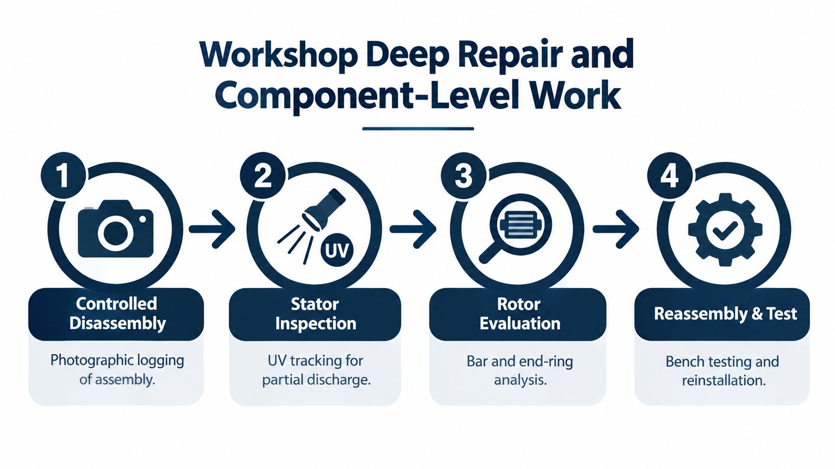
Controlled disassembly should expose the cause without destroying evidence. Inspect the stator for heat damage, contamination, loosened laminations, tracking, and winding movement. UV inspection can help identify partial-discharge activity and tracking that ordinary visual inspection may overlook. The rotor needs its own examination, including bars, end rings, shaft journals, fan components, and signs of rub or imbalance.
Repair by component, not by assumption
A rewind is appropriate only after the winding and core condition justify it. The repair record should identify the winding arrangement, conductor details, insulation system, connections, and test results. Removing a winding without preserving its data can make the replacement electrically correct in theory but wrong for the application.
Mechanical work needs the same discipline. Bearing seats may require remachining, shafts may need restoration, and dynamic balancing may be necessary after rotor work. Each intervention should close against an acceptance criterion. A completed task is not evidence of a successful repair.
Useful workshop checkpoints include:
- Stator acceptance: Core-loss results support the repair, and the insulation system passes the required tests.
- Winding acceptance: Resistance, surge response, insulation resistance, and high-potential results are documented.
- Rotor acceptance: Bar, end-ring, shaft, and balance findings are recorded against the repair scope.
- Mechanical acceptance: Fits, runout, bearing installation, and balance results meet the agreed criteria.
- Assembly acceptance: Rotation is smooth, clearances are correct, and all accessories match the original configuration.
An exchange unit needs one more control before dispatch. Verify the nameplate and frame, perform a no-load run, capture current and vibration behavior, and attach a signed test sheet to the crate and the electronic maintenance record. A motor that is “ready to ship” without a recorded baseline only transfers uncertainty from the workshop to the plant.
Spare Parts, Compatibility, and Pre-Dispatch Checks
A part can fit physically and still create the next outage. A bearing may match the shaft diameter but fail at the motor's actual load or speed. An encoder may mount correctly yet deliver an incompatible protocol or feedback signal to the drive. A replacement motor can share the same nominal power while differing in frame, mounting, cooling, insulation, or service conditions.
As noted in the repair-path comparison, many failed motors remain viable repair candidates. An automatic horsepower threshold should therefore start a compatibility review, not force a replacement decision. A bearing intervention or winding repair may return the asset faster, especially when a replacement requires alignment work, new accessories, or control changes.
The threshold used by a plant is only a screening rule. A smaller motor may still drive a critical process, operate in a contaminated area, require difficult alignment, or include a nonstandard accessory. Review the duty cycle, failure mode, shutdown window, and transport risk before choosing an on-site repair, workshop repair, or exchange unit.
Compatibility checks that prevent another outage
Before ordering parts or dispatching a repaired motor, confirm:
- Mechanical identity: Frame, shaft extension, mounting arrangement, bearing seats, coupling fit, and enclosure dimensions.
- Electrical identity: Voltage, frequency, connection method, insulation class, service conditions, and terminal arrangement.
- Environmental protection: IP rating, cooling method, ambient exposure, contamination profile, and hazardous-area requirements where applicable.
- Feedback compatibility: Encoder type, protocol, mounting, signal wiring, and the installed drive firmware requirements.
- Bearing suitability: Series, internal clearance, insulation needs, lubrication arrangement, load, speed, and shaft-current risk.
- Documentation: Nameplate photographs, dimensional drawings, winding or accessory records, and the approved repair scope.
Match spare parts against the motor's actual configuration, not a catalogue description alone. Confirm whether the unit is intended for inverter duty, variable speed, frequent starts, high ambient temperature, or a corrosive installation. These conditions can change the correct bearing arrangement, insulation requirements, cooling configuration, and feedback hardware.
The pre-dispatch file should travel with the physical unit and enter the CMMS record. Include nameplate verification, insulation resistance, no-load current, vibration baseline, accessory confirmation, and the approving person. Attach the signed test sheet to the crate. Procurement should answer two questions before release: will it fit, and what recorded evidence shows it is ready?
Return-to-Service Testing That Actually Proves It
A no-load spin can hide a problem that appears only after the motor carries process load. Return-to-service testing should therefore compare the repaired asset with its own pre-failure history whenever that history exists. If the baseline is missing, create one deliberately and label it as a new reference.
At first energization, verify rotation direction and observe current behavior. Don't treat a smooth start as proof of a healthy repair. A current imbalance, abnormal acceleration, unexpected noise, or unstable feedback signal deserves investigation before the motor is handed back to operations.
Read the trend, not only the pass or fail line
Run the motor under a controlled load and capture vibration, temperature, current, voltage, and audible noise. Thermal imaging during a sustained loaded run can expose uneven heating at terminals, bearings, cooling paths, or the frame. Bearing tones and ventilation signatures should be compared with the known condition of the asset, not judged only by whether the motor sounds acceptable to a person standing nearby.
Repeat insulation resistance and polarization checks after the run when the repair scope and risk justify it. Heat can reveal weakness that wasn't visible during a cold test. If one channel shows a soft deviation while the others look normal, hold the handover, verify the instrument and sensor, inspect the relevant component, and repeat the measurement under the same conditions.
| Test channel | Metric | Pass band versus pre-failure baseline | Soft deviation usually means |
|---|---|---|---|
| Electrical supply | Voltage, current, phase balance | Stable and consistent with the recorded baseline | Supply imbalance, connection resistance, or load change |
| Vibration | Overall level and bearing-frequency content | No unexplained rise from the baseline | Alignment, balance, bearing, looseness, or structural resonance |
| Thermal | Bearing, terminal, frame, and ventilation temperatures | No localized heating pattern absent from the baseline | High resistance, poor cooling, overload, or lubrication issue |
| Acoustic | Bearing and airflow signatures | No new tonal or rubbing component | Bearing damage, fan interference, or mechanical contact |
| Insulation | Resistance and polarization behavior | Consistent with the repair record and operating condition | Moisture, contamination, or heat-driven insulation weakness |
| Process response | Speed, torque, flow, or driven output | Stable operation at the expected operating point | Control, coupling, load, or feedback problem |
The handoff should include the final test sheet, refreshed vibration and thermal baselines, photographs of critical connections, the confirmed failure mode, and any new inspection recommendation. A structured equipment condition monitoring approach gives the next technician a starting point instead of forcing a new investigation from zero.
Building a Repair Habit That Outlasts the Next Trip
A repaired motor should leave the event better understood than it was before the trip. The team needs a named failure mode, a documented baseline, a record of parts and measurements, and a clear view of what could cause the same failure again.
That record changes the next decision. If the motor trips again, the technician can distinguish a repeat of the original defect from a new operating problem. If contamination, heat, misalignment, or feedback mismatch caused the first event, the maintenance plan can address that condition instead of scheduling another identical repair.
Close the loop after every failure
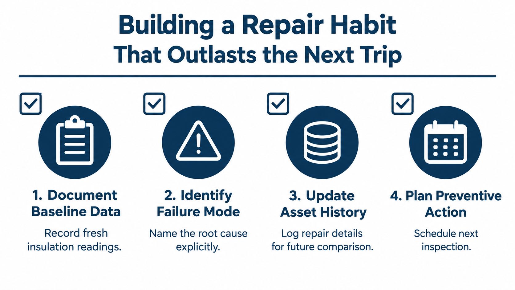
Use the following handoff as a minimum operating habit:
- Document baseline data: Save insulation readings, resistance values, vibration, temperature, current, photographs, and test conditions.
- Identify the failure mode: State whether the evidence points to winding insulation, bearing damage, contamination, alignment, supply quality, feedback, cooling, or another defined cause.
- Update asset history: Record the repair path, parts, measurements, acceptance results, and any change in operating limits.
- Plan preventive action: Assign the next inspection, cleaning, lubrication, alignment check, electrical test, or condition-monitoring review to a named owner.
IoT sensors and condition-monitoring systems can narrow the diagnostic gap before the next trip by capturing vibration, temperature, current, and operating behavior during normal service. They don't replace skilled diagnosis. They give the technician better evidence before the motor is opened and help the reliability team separate a developing defect from a one-time disturbance.
The repair decision should also become part of the asset strategy. A plant with mixed motor classes needs clear rules for when a motor stays installed, when it goes to a controlled workshop, when a verified exchange unit is appropriate, and when replacement is the only responsible option. The rules should account for duty cycle, criticality, transport risk, contamination, available lifting equipment, spare compatibility, and the actual shutdown window.
The target isn't a motor that has merely been repaired. It's a motor whose next failure is easier to predict, whose history is usable, and whose recovery path has already been tested on paper.
DUCHENG Industrial supports industrial drive and motor-related recovery through structured on-site diagnosis, medium-voltage reconditioning, workshop deep repair, spare-part compatibility review, and pre-dispatch verification. If your plant needs a repair path matched to the asset and shutdown window, contact DUCHENG Industrial with the motor data, failure symptoms, and available outage constraints.