
A field-tested motor drive repair workflow covering on-site triage, fault isolation, bench repair, MV reconditioning, spare-parts checks, and safety.
The motor has stopped, production is waiting, and someone is already asking whether the drive can be reset. At midnight, that pressure is understandable. It's also how a manageable trip becomes a damaged power stage, a second fault, or an unsafe restart.
Motor drive repair should begin as a lifecycle decision, not a hunt for the first replaceable board. Industrial motor repair has long been a core maintenance activity. A U.S. Department of Energy survey reported that in 1993, at least 2 million motors between 5 and 500 hp were repaired in the United States, representing more than 200 million hp of equipment, with roughly 4,100 repair shops and about $2 billion in annual repair revenue at the time (U.S. Department of Energy survey summary). The practical lesson remains relevant: a trip is one event in the asset's life, and the right response may be on-site triage, controlled restart, bench repair, medium-voltage reconditioning, or replacement planning.
Table of Contents
- The First Hour After a Drive Trip
- On-Site Triage and Controlled Restart
- Fault Isolation Beyond the Drive Itself
- Bench-Level Component Repair
- On-Site Reconditioning for MV Drives
- Spare Parts Matching and Pre-Dispatch Checks
- Safety, Documentation, and the Repair Mindset
The First Hour After a Drive Trip
The HMI shows a stopped motor, the drive lineup is still energized, and three technicians are looking toward the reset key. The lead technician doesn't touch it yet. First, they identify the exact drive that tripped, confirm the active alarm on the HMI and keypad, and record the time, process condition, commanded speed, output current, and any recent change in load.
That first pause separates a one-time disturbance from a recurring fault. A single overvoltage event during a process transition deserves a different response from an overcurrent that appears every time a conveyor starts carrying product. The alarm history matters because the latest code may be the consequence, not the original cause.
Practical rule: A reset is a test only after the hazard and the fault path are understood. It isn't a diagnosis.
The technician also checks the equipment around the drive. Is the motor mechanically free? Has a pump seized? Is a downstream valve closed? Has a conveyor jammed? Are there signs of smoke, unusual odor, heat, moisture, dust buildup, or a tripped upstream protective device? A drive can report an overcurrent while the problem sits in the motor, feeder, coupling, or process.
Stop the unsafe restart
Before opening a cabinet or testing conductors, the team establishes the correct isolation boundary. That includes the incoming supply, any separate control supply, stored energy in the DC link, and remote start commands from the control system. The technician confirms that the affected equipment is identified, not merely the nearest cabinet in the lineup.
A useful field reference is this guide to the first steps after a drive trip, but the site's approved electrical safety procedure always governs the work. Keep personnel outside the applicable arc-flash boundary until the equipment is in the required safe state, and don't assume that a dark display means the DC bus is discharged.
Choose the repair branch
At the end of the first hour, the team should be able to place the event into a working branch:
- On-site triage: Use this when the fault may be external, the evidence is incomplete, or a controlled restart can safely confirm the diagnosis.
- Bench repair: Choose this when the drive has internal damage, unstable power-stage measurements, contaminated boards, or repeat trips after external causes are cleared.
- MV on-site reconditioning: Consider this when removal and transport would consume the shutdown window, the defective assembly is field-replaceable, and the site can support safe MV work.
- Spare-parts pre-dispatch: Use this when a verified exchange unit can restore service faster than component repair, but only after compatibility checks.
That decision prevents the common mistake of treating every fault as a board replacement.
On-Site Triage and Controlled Restart
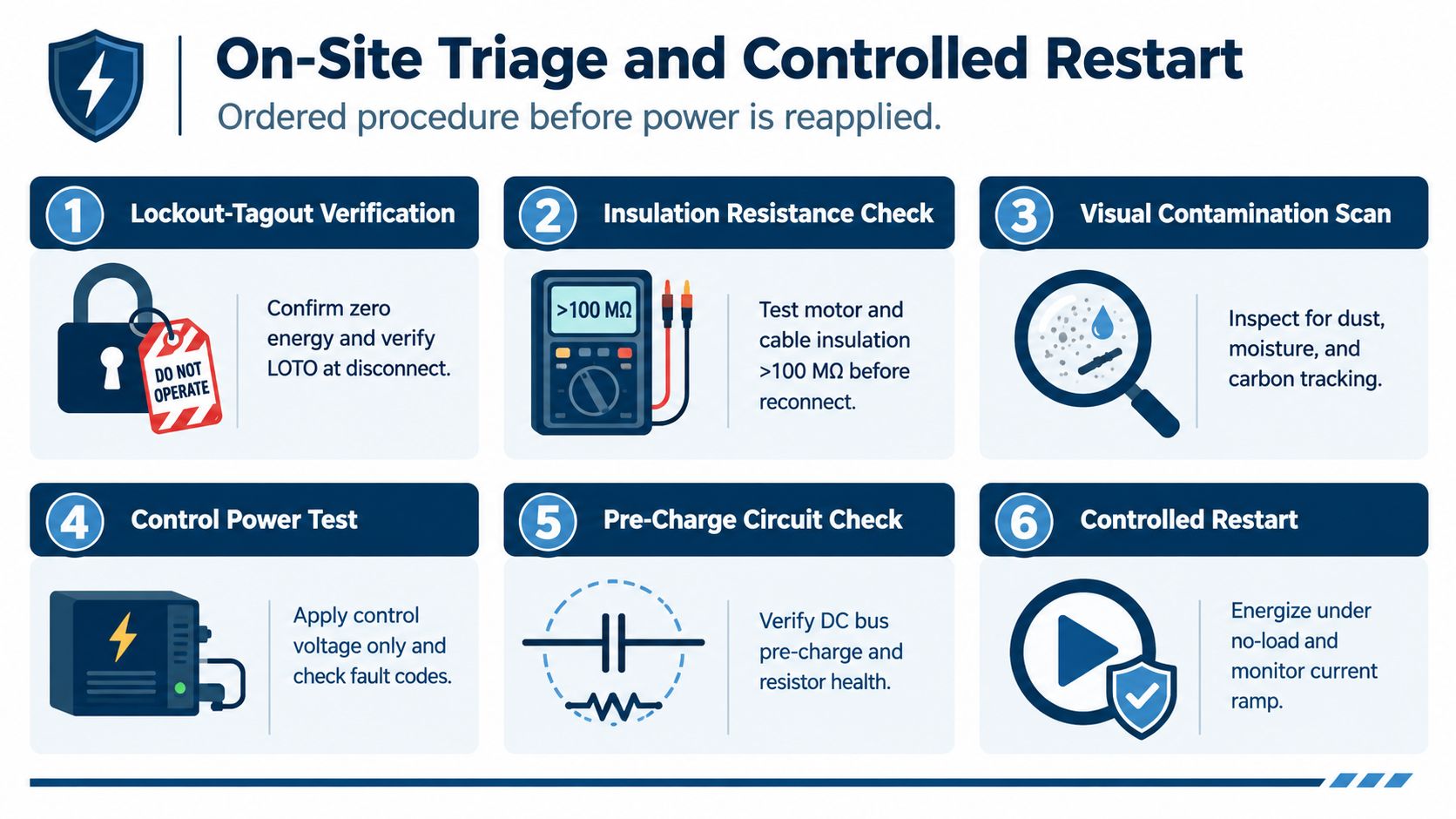
A controlled restart should follow gates, not urgency. Each gate requires a measurement, observation, or documented confirmation. If one check fails, stop the restart and move the drive into the appropriate repair branch. The choice is a lifecycle decision: continue on-site only when evidence supports it, send the unit for bench repair when internal damage is likely, use MV on-site reconditioning when removal would consume the shutdown window, or verify a spare before dispatch when exchange is the faster safe option.
Follow the isolation sequence
-
Verify lockout and tagout. Identify the correct disconnect, apply the personal lock and tag, and confirm the isolation point against the electrical drawing. Check for backfeed from auxiliary supplies, bypass circuits, braking equipment, and control transformers.
-
Prove zero energy. Check the approved meter on a known live source before and after testing. Measure the DC bus at the specified test points, phase to phase, and phase to ground where the procedure requires it. A dark display or discharge indicator does not prove a safe bus.
-
Respect stored energy. Wait the manufacturer's specified discharge period, then verify residual voltage. DC-link capacitors can retain dangerous energy after incoming power is removed. The practical VFD repair workflow places DC-bus verification before diagnostic testing for this reason.
-
Test the motor and feeder. Disconnect the motor from the drive before insulation resistance testing. Test the windings and cable with a suitable megohmmeter at the voltage required by the equipment and site procedure. Treat the infographic's greater-than-100 MΩ checkpoint as an acceptance value only when it matches the approved site standard and equipment requirements. A result below that limit keeps the motor or cable under suspicion.
-
Inspect the power path. Check input fuses, breaker indications, terminals, busbars, cooling passages, filters, and evidence of carbon tracking or moisture. Loose connections can produce heat, voltage imbalance, and intermittent trips without a clear alarm history.
-
Apply control power first when possible. Retrieve fault history and confirm the active code without energizing the power stage. Review motor data, control mode, acceleration and deceleration values, current limits, feedback selection, bypass status, and external interlocks. Parameters must match the motor nameplate, application, and approved backup.
Make the first restart deliberately
After the checks pass, clear personnel and tools, confirm the mechanical area is safe, establish communication with operations, and assign stop authority. Maintain the required arc-flash boundary and PPE level. If the drive faults immediately during power-up, stop. Repeated power cycling can erase evidence and increase damage.
For a no-load or uncoupled test, monitor output current, phase balance, acceleration response, DC-bus behavior, motor noise, vibration, and temperature. A stable test supports an on-site restart decision, but production loading may expose a separate motor, cable, feedback, or mechanical fault. Use this VFD troubleshooting guide for fault-code and measurement logic before deciding whether the unit stays in service, moves to bench repair, or requires a field reconditioning or spare-parts plan.
Fault Isolation Beyond the Drive Itself
The drive alarm tells you what its protection system detected. It doesn't automatically identify the failed component. Repeat trips often originate in the motor, cable, feedback circuit, mechanical load, or operating parameters, so pulling a control board before staged testing can destroy useful evidence.
A ground-fault indication points the investigation toward insulation, cable routing, moisture, contamination, or a damaged motor winding. An IGBT desaturation trip points more strongly toward the power module, gate-drive path, or an abnormal current event that forced the protection circuit to act. An overcurrent synchronized with a load transition suggests a process or mechanical problem until measurements prove otherwise.
Encoder feedback loss deserves a separate path. Check the encoder supply, connector seating, shield termination, cable continuity, and feedback data while moving the shaft as permitted by the machine procedure. A drive that runs correctly in open-loop conditions but trips as soon as feedback is enabled has a different repair boundary from a drive that fails its power-stage self-test.
Use staged substitution
The sequence should reduce uncertainty:
- Review the fault history and trend: Compare the alarm with speed command, output current, process state, and recent maintenance.
- Test the feeder and motor separately: Isolate the drive, inspect the cable, and perform approved insulation and continuity checks.
- Run an uncoupled test: A no-load spin can separate a mechanical load problem from an electrical control problem, provided the motor and machine can be safely uncoupled.
- Substitute deliberately: A known-good motor or cable can narrow the suspect list, but only when its ratings, feedback arrangement, and application suitability are confirmed.
- Review parameters: Check motor data, current limits, ramp settings, switching behavior, feedback configuration, and control mode against the approved record.
- Measure the DC link under operation: Abnormal ripple, unstable pre-charge behavior, or input imbalance can implicate the supply path rather than the inverter output stage.
| Symptom | Likely Source | First Check |
|---|---|---|
| Ground-fault trip at enable | Motor insulation, feeder, moisture, contamination, or output stage | Isolate motor and cable, then perform approved insulation tests |
| IGBT desaturation trip | Power module, gate-driver circuit, or severe phase fault | Check IGBT junction behavior and gate signals with the DC link discharged |
| Overcurrent during load transition | Mechanical jam, acceleration setting, motor issue, or power stage | Compare current with the process event and test uncoupled operation |
| Encoder feedback loss | Encoder, feedback cable, connector, supply, or control interface | Verify supply, continuity, shielding, and feedback data |
| DC-bus ripple anomaly | Input supply, rectifier, capacitor bank, or loose power connection | Measure supply balance and DC-link behavior under controlled conditions |
A drive that passes a bench power-up may still fail in the plant because the plant supplies the cable capacitance, motor insulation condition, mechanical inertia, and process load. That's why isolation should finish with a documented root-cause hypothesis, not merely a cleared alarm.
Bench-Level Component Repair
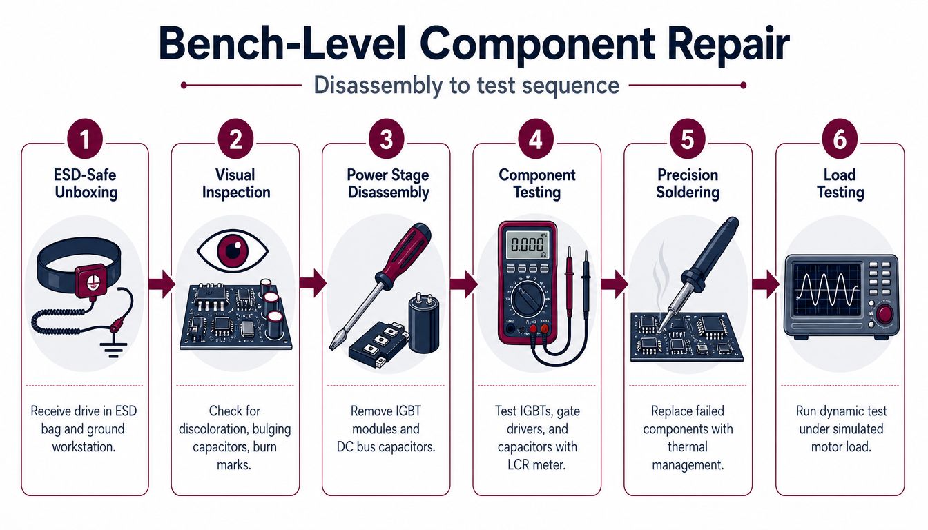
A returned drive is evidence from a failed event, not a unit to power immediately. Before opening it, record serial information, the reported fault, photographs, missing covers, connector condition, and packaging damage. Set up an ESD-safe workstation, ground the bench, and keep removed hardware identified by its original location.
Inspect before measuring
Start with a visual inspection. Look for PCB discoloration, bulging or leaking capacitors, cracked solder joints, burned gate-driver areas, carbon tracking, blocked fans, moisture, and conductive dust. Examine crimped power terminals and busbar joints closely. A fastener may be tight even when the crimp or contact surface has degraded.
Discharge the DC link through the approved discharge path, then verify zero energy with a known-good meter. A dark display does not prove that the bus is safe. After isolation is confirmed, work from the power stage toward the control and sensing circuits.
Measure the parts that can explain the reported trip:
- DC-link condition: Check capacitance and ESR against the manufacturer's requirements. A commonly used repair rule treats electrolytic capacitors below 85% of rating as candidates for replacement, as described in this VFD repair guide. Use that threshold as a diagnostic guide, not as a replacement for the manufacturer's limits.
- IGBT behavior: Check shorts, leakage, diode behavior, and gate-emitter integrity. A failed module can damage its driver, so replacing the driver alone leaves a likely failure path untested.
- Gate-drive isolation: Verify optocoupler or isolated-driver operation, supply rails, pulse transmission, and abnormal switching levels.
- Current sensing: Inspect shunts and current-sense resistors for drift, hairline cracks, heat damage, and weak solder joints.
- Cooling circuits: Test fans, fan supplies, tachometer or alarm circuits, heat-sink contact, and thermal interfaces.
Bench discipline: Test the circuits that command, protect, and measure an alarmed component before replacing that component.
Use controlled power and a realistic load
A current-limited bench supply or controlled power-up rig can expose a short while limiting fault energy. It also allows the technician to observe control power, pre-charge behavior, gate signals, and fault response in sequence.
Shortcuts usually show up during commissioning. Installing a gate driver without checking the IGBT module, changing a fan without testing its alarm circuit, or overlooking terminal crimp integrity can produce a drive that starts on the bench and fails under plant conditions. The repair decision should therefore follow the evidence: repair the board when the fault is bounded, replace the assembly when damage has spread, and return the unit for further investigation when the test boundary is unclear.
The final test needs a load bank or equivalent motor arrangement that reflects the expected operating current and control mode. Record phase current, DC-bus behavior, alarms, temperature, and thermal-image findings during the run. A drive is ready for dispatch when the repaired circuits remain stable under a controlled representation of service duty, not merely because it powers up.
<iframe width="100%" style="aspect-ratio: 16 / 9;" src="https://www.youtube.com/embed/LJYfZlMQ8co" frameborder="0" allow="autoplay; encrypted-media" allowfullscreen></iframe>On-Site Reconditioning for MV Drives
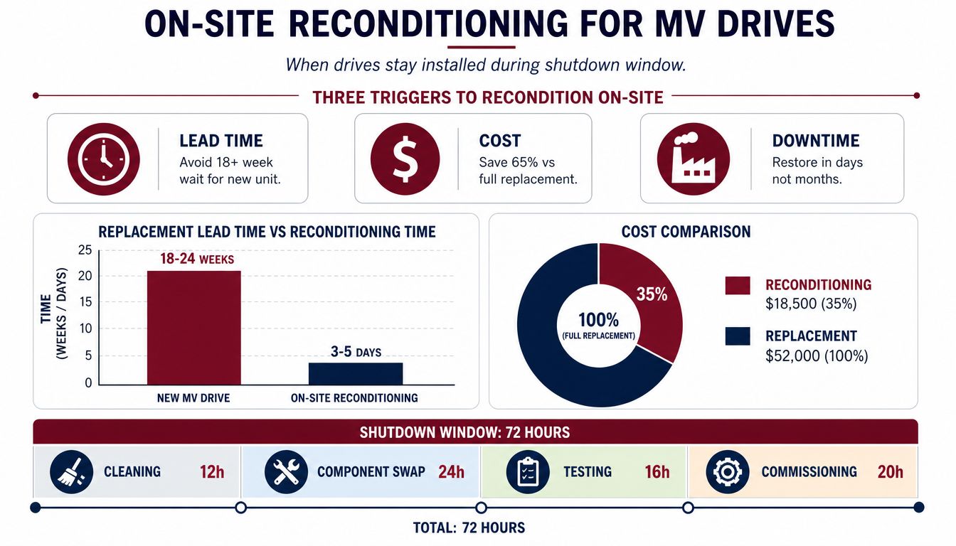
A medium-voltage drive may be installed in a location where removal requires a crane, a specialist transport plan, and a shutdown longer than operations can provide. In that situation, the question isn't whether the drive can be repaired. The question is whether the repair boundary, site controls, and available outage support make on-site reconditioning the lower-risk lifecycle choice.
Consider a planned shutdown with a narrow work window. A replacement lead time exceeds the outage, the diagnostic evidence points to a field-replaceable assembly, and the site can provide qualified MV isolation, ventilation, access control, and rigging support. Those are the three conditions that make an on-site branch credible. If any one is missing, shipping the unit or replacing it may be safer.
What the field visit includes
The service team coordinates the outage with operations, electrical authority, production, and safety personnel. The upstream switchgear is locked and tagged, the isolation is independently verified, and the drive's own discharge system is used according to the manufacturer's procedure. Technicians don't improvise grounding methods or assume that a visible isolation point has removed all stored energy.
Once the cabinet is safe, the work stays sectional. Rectifier or inverter cubicles may be inspected, cleaned, and tested. Suitable field-replaceable items can include gate-driver boards, cooling fans, fiber-optic cables, and high-voltage fuses, provided the exact assembly and ratings are confirmed before removal.
Know the boundary
A site is not a workshop. Transformer rewinds, complete power-stack rebuilds, and work requiring controlled impregnation processes belong in facilities equipped for those tasks. Attempting them in an operating area increases contamination, quality, and safety risk.
Recommissioning follows the same logic as a bench return, adapted to the installed system. Verify connections, cooling, fiber paths, protection circuits, parameters, and insulation requirements. Energize at reduced voltage first where the equipment design permits it, confirm control response, then progress through no-load and staged-load testing. Record readings at every stage so the handover reflects what was tested, not what the team expected to find.
Spare Parts Matching and Pre-Dispatch Checks
An exchange drive can look identical to the failed unit and still be wrong for the machine. Mechanical fit is only the first filter. Firmware, control-board revision, feedback interface, power rating, switching requirements, and option modules can all change whether a swap will start cleanly or create a new fault.
Treat the spare as an engineered match. Before dispatch, compare the target unit's records with the donor unit's identification and configuration.
| Verification Layer | Specific Checks | Failure Caught |
|---|---|---|
| Mechanical fit | Frame size, mounting points, busbar spacing, terminal orientation, covers, and cable entry | Unit cannot be installed safely or connections are forced |
| Electrical equivalence | Voltage class, current rating, overload capability, switching requirements, braking arrangement, and filter needs | Power stage is unsuitable for the motor or supply |
| Control compatibility | Firmware revision, control-board variant, parameter set, option modules, and feedback interface | Drive powers up but cannot communicate or control the machine |
| Application extras | Line filter, brake chopper, encoder card, auxiliary supply, thermal input, and external interlocks | Secondary equipment is missing or incompatible |
Build the dispatch file
The minimum dispatch packet should contain the donor serial number, target machine identifier, recorded fault history, parameter backup, connector and terminal photos, bench test results, and the installation notes. If the failed unit still communicates, upload its parameter set before removal. If it doesn't, recover the latest approved backup rather than copying uncertain values from memory.
The bench should run a power-on self-test, verify the control display and alarm response, exercise simulated digital and analog I/O through a loopback, and perform a no-motor run that checks the output stage under controlled conditions. Feedback cards and communications interfaces need their own confirmation, not just a visual inspection.
A useful pre-dispatch review asks one question: what could make this unit fail during the first energization even if the hardware is healthy? The answers usually involve wrong parameters, mismatched options, missing interlocks, incorrect terminal mapping, or an unverified feedback path.
DUCHENG Industrial provides multi-brand drive diagnosis, workshop repair, parameter recovery, functional testing, spare-parts identification, and pre-dispatch verification as part of its lifecycle electrical services. That type of structured handover is more valuable than sending a visually similar unit with an incomplete record.
Safety, Documentation, and the Repair Mindset
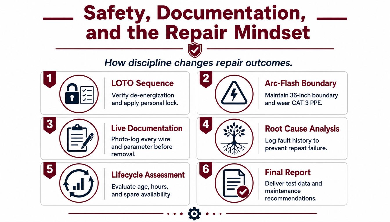
A repair is complete only when the equipment is safe, the cause is recorded, the test result is witnessed, and the next technician can understand what happened without rebuilding the investigation from scratch. LOTO, arc-flash controls, and PPE aren't separate from technical quality. They protect the people and the evidence needed to make a sound repair decision.
LV and MV cabinets require different site procedures, boundaries, access controls, and PPE selections. The electrical authority should define the work method, verify de-energization, control stored energy, and confirm when the enclosure can be opened. For every intervention, the lead technician should preserve the fault history, parameter backup, insulation results, photos of wiring and terminal condition, and evidence of torque or rework checks.
Make the record useful
Good documentation answers four questions:
- What happened? Capture the alarm sequence, process state, operating conditions, and operator observations.
- What was tested? Record isolation, insulation, power-stage, feedback, cooling, and load-test results.
- What changed? Log replaced parts, serial traceability, parameter revisions, wiring changes, and firmware status.
- What happens next? Assign condition checks, environmental improvements, spare reviews, and a follow-up date.
The maintenance history should also preserve the decision itself. If the team repaired an aging drive instead of replacing it, record why. Reliability risk, spare-parts availability, obsolescence, lead-time exposure, and criticality all matter. Guidance on VFD failure diagnosis and replacement decisions warns that a low repair price can be misleading when boards, fans, or power assemblies are becoming unavailable.
A broader maintenance program should address contamination, heat, airflow, moisture, connection tightness, capacitor condition, firmware, and parameter backups. Preventive drive data cited in industry guidance found 20% of examined drives needed replacement parts, 47% had problems that did not require parts, and 33% had no problems, which supports inspecting and correcting conditions before assuming every service event requires component replacement.
Closing checklist
Before closing the job, the lead technician confirms:
- Isolation verified: The correct energy sources were locked, tagged, tested, and released through the approved process.
- Parameters backed up: The final configuration is stored with the asset record.
- Root cause recorded: The fault is linked to the drive, motor, cable, process, environment, or an unresolved investigation.
- Parts traceability logged: Replaced assemblies and donor-unit details are documented.
- Test run witnessed: Operations and electrical personnel agree that the staged test reflects the approved service condition.
- Documentation filed: Fault logs, measurements, photos, and handover records are accessible.
- Next condition-monitoring date scheduled: The repaired asset has a defined follow-up rather than disappearing into normal operation.
A midnight trip should end with more than a running motor. It should leave the plant with a safer restart, a defensible repair decision, and better information for the next event.
If your site is dealing with a recurring trip, an aging VFD, an MV shutdown constraint, or an uncertain exchange unit, ask DUCHENG Industrial to support the diagnosis before you commit to a reset, repair, or replacement. Its lifecycle services cover on-site troubleshooting, workshop motor drive repair, MV reconditioning, preventive maintenance, and pre-dispatch spare verification across China and Southeast Asia.