
VFD Troubleshooting Guide. Master VFD troubleshooting with this step-by-step guide covering fault isolation, common error codes, safe restart procedures
The drive trips just as the production line reaches its critical run. The operator resets it, the motor starts, and everyone hopes the alarm was a nuisance. Ten minutes later, the same fault returns. At that point, the problem isn't only downtime. The team has lost the evidence that could have shown whether the cause was a loose termination, restricted cooling, a bad parameter, a mechanical load problem, or a failing power stage.
A disciplined VFD troubleshooting guide starts with evidence, not repeated resets. A field survey compiled from hundreds of drives found 33% with no problems, 47% with problems that didn't require replacement parts, and 20% requiring replacement parts in a preventive-maintenance analysis published in 2010, as documented in this field survey of VFD maintenance findings. The practical lesson is straightforward. Most service calls deserve inspection, measurement, and parameter verification before anyone condemns the drive.
Table of Contents
- When Your VFD Trips at 3 AM
- The Internal vs External Isolation Sequence
- Common Fault Codes and What They Really Mean
- Diagnosing Recurring Faults That Hide in Plain Sight
- Safe Restart Rules and Escalation Criteria
- Networked Drives and Data-Driven Troubleshooting
- Your Complete VFD Troubleshooting Methodology
When Your VFD Trips at 3 AM
At 3 AM, the first instinct is understandable. Production is stopped, the operator is under pressure, and the drive display shows a fault code that appears to point directly at the equipment. Someone clears the alarm, someone else checks the motor, and the line is restarted before the original conditions have changed. If the motor runs, the incident gets closed as a reset rather than treated as a diagnostic event.
That approach often creates the next outage. A drive that trips during deceleration, after the cabinet heats up, or only when a conveyor reaches a particular load is giving you a pattern. Resetting it removes the immediate symptom but leaves the pattern untouched. It can also erase useful fault history and make the next technician start with less information.
Why replacement is often the wrong first move
The maintenance data points to a better order of operations. The same survey found 47% of VFDs with problems that didn't require replacement parts, while 20% required replacement parts. Those findings don't mean hardware failures are rare or harmless. They mean the first response should separate external conditions and serviceable issues from genuine internal damage.
External causes include supply imbalance, loose power wiring, a restricted cooling path, a mechanically overloaded machine, incorrect motor data, or a safety and control signal that has opened. Internal causes can include damaged rectifier components, failed insulated-gate bipolar transistors, deteriorated fans, or aging DC-bus components. The technician's job is to distinguish these categories before selecting a remedy.
What a useful incident record contains
A reliable record takes only a few minutes if the drive remains safe to approach. Capture the exact fault text, time of trip, running speed, load condition, acceleration or deceleration state, cabinet temperature, and any unusual sound or smell. Record what changed before the trip, including cleaning, parameter edits, motor work, line switching, or a new production recipe.
Practical rule: A fault code is a starting point, not a verdict. The timing and operating conditions usually reveal more than the code alone.
The rest of the investigation should follow the same order every time. First preserve evidence. Then isolate external conditions. After that, test the drive and motor circuit safely. Only then decide whether a controlled restart, repair, reconditioning, or replacement is justified.
The Internal vs External Isolation Sequence
The safest workflow begins at the drive interface and moves outward before it moves inward. Read the display and fault history first. Don't power-cycle a drive until you've recorded the alarm, auxiliary information if available, and the operating state at the moment of failure.
Start with the display, then inspect the environment
Confirm the fault against the manual for the exact drive model and firmware. Similar fault names can represent different detection logic, and code numbers aren't universal across product families. The display tells you what protection function operated. It doesn't prove that the corresponding internal component failed.
Next, stop and inspect the installation. Look for conductive dust, moisture, oil film, salt deposits, blocked filters, failed fans, discoloration, a burnt smell, loose covers, and signs of overheating around terminals. Check whether the cabinet has recently gained heat-producing equipment or lost ventilation. A dirty heatsink can reduce cooling without producing an obvious alarm until the drive has operated long enough to absorb thermal stress.
Check wiring and supply quality before component testing
With the equipment isolated under the site's electrical safety procedure, examine incoming power connections and motor terminals. Loose terminations create heat, voltage drop, intermittent phase loss, and damaging electrical stress. They can also contribute to rectifier or IGBT damage, which is why a loose connection shouldn't be dismissed as a minor maintenance defect.
The field workflow described in this VFD troubleshooting sequence places visual inspection before deeper electrical testing and reports that the method resolves about 90% of field failures without drive replacement. The same guidance says incoming three-phase voltage should remain within a 5% deviation to reduce nuisance trips and secondary damage. Measure at the drive input terminals, not only upstream, and compare phase-to-phase readings under the operating condition that produces the fault.
Compare input and output behavior
After confirming the input, measure current and voltage balance in a controlled condition. Unequal input current can indicate supply, connection, or rectifier concerns. Unequal output current can point toward motor cable problems, winding issues, a phase connection fault, or a drive output-stage problem.
Use the sequence below as a field checklist:
- Preserve the fault record. Write down the code, timing, speed, load, and recent changes.
- Inspect the cabinet. Check contamination, cooling, wiring condition, and visible thermal damage.
- Verify the supply. Measure all incoming phases at the drive and assess balance under load.
- Inspect the motor circuit. Check terminals, cable condition, insulation, grounding, and mechanical freedom using approved procedures.
- Review parameters. Confirm motor nameplate data, current limits, ramp times, control mode, feedback settings, and protection thresholds.
- Test under controlled conditions. Reproduce the fault only after the cause has been assessed and the restart has been authorized.
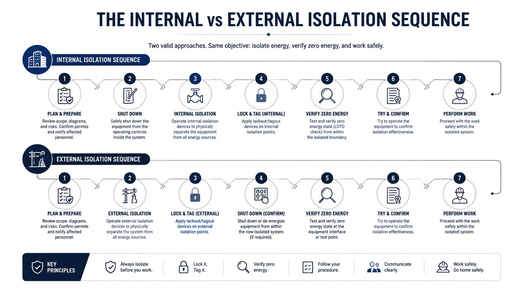
The most common mistake is skipping the cabinet and installation inspection because the display appears authoritative. A drive can correctly report overcurrent while the cause is a jammed machine, incorrect acceleration, or a shorted cable. It can report overtemperature while the power stage is healthy but the cooling path is obstructed. Internal testing comes after external isolation, not before it.
Common Fault Codes and What They Really Mean
Fault codes are useful because they classify the protection event. They become useful for maintenance only when the technician connects each code to timing, load, temperature, and electrical measurements.
Independent troubleshooting guidance identifies a small group that drives many service calls, including overcurrent, overvoltage, undervoltage, overtemperature, ground fault, phase loss, and communication or feedback errors. One guide reports that overtemperature represents 50% to 60% of reported VFD issues, while another reports that incorrect parameters account for roughly 60% of post-installation faults and that overcurrent represents 35% to 45% of trips, as summarized in this fault-pattern troubleshooting reference. These figures support a practical priority order, parameter review, load assessment, and cooling inspection before board replacement.
| Fault Code | Typical Root Cause | First Diagnostic Step |
|---|---|---|
| Overcurrent | Jammed or overloaded machinery, shorted motor circuit, aggressive acceleration, or incorrect motor data | Check when the trip occurs, then inspect the load, motor circuit, and acceleration setting |
| Overvoltage or high DC bus | Regenerative energy during deceleration, braking problems, or abnormal supply conditions | Review deceleration behavior and check DC-bus response under load |
| Undervoltage | Supply dip, loose input connection, phase problem, or upstream disturbance | Measure all input phases at the drive during the event |
| Overtemperature | Restricted airflow, contaminated heatsink, failed fan, or excessive cabinet heat | Inspect the cooling path and compare temperature behavior over time |
| Ground fault | Motor or cable insulation breakdown, moisture, contamination, or wiring damage | Isolate the motor circuit and test the motor and cable separately |
| Phase loss | Missing supply phase, loose terminal, fuse issue, or output connection problem | Check phase presence and balance at the relevant terminals |
| Communication or feedback error | Network wiring, shielding, configuration, feedback sensor, or control-system issue | Check link status, signal path, configuration, and event timing |
Overcurrent is a symptom with a timing signature
An overcurrent trip at startup deserves a different investigation from one that appears after several minutes. At startup, inspect mechanical freedom, acceleration time, motor data, and the motor cable. During operation, compare current with the expected load and check for a process condition that increases torque demand.
Don't raise current limits to stop the alarm. That can conceal a mechanical fault or expose the motor and drive to stress they weren't configured to handle. If the machine accelerates normally at light load but trips when product enters the process, inspect the machine and process first.
Overvoltage and undervoltage point in opposite directions
An overvoltage event during stopping often involves energy returning from the motor to the DC bus. Check the deceleration profile, braking hardware, and the behavior of the load during the stop. A longer deceleration may solve the condition when process requirements allow it, while a braking solution may be necessary when the load repeatedly regenerates.
Undervoltage requires attention to the supply path. Measure at the drive input while the fault condition is present or being reproduced. Loose lugs, switching events, weak upstream equipment, or phase loss can all create a drive-side voltage problem even when the upstream panel appears normal.
Heat faults usually require a physical inspection
Overtemperature isn't fixed by clearing the alarm. Check fan operation, filters, heatsink cleanliness, cabinet temperature, and the drive's operating duty. A fan can spin during a quick inspection and still fail intermittently as its bearings warm. A cabinet can also remain apparently clean while conductive contamination has settled inside the drive.
For brand-specific reporting and consistent handover between shifts, use a documented method for reporting fault codes across drive brands. Consistent naming prevents a recurring fault from being treated as a new event because different technicians describe it differently.
<iframe width="100%" style="aspect-ratio: 16 / 9;" src="https://www.youtube.com/embed/sKbO6ghAO8o" frameborder="0" allow="autoplay; encrypted-media" allowfullscreen></iframe>A ground fault or phase-loss indication should never be treated as a nuisance until the circuit has been tested safely. Communication faults deserve the same seriousness. The power stage may be healthy while the drive is being stopped by a missing enable signal, bad feedback data, network noise, or a control timeout.
Diagnosing Recurring Faults That Hide in Plain Sight
A drive that trips once and a drive that trips every shift aren't the same diagnostic problem. The first may respond to a corrected external condition. The second requires you to identify what changes before the trip, often temperature, vibration, load, speed, moisture, or operating duration.
The recurring-fault mistake is to repeat the initial checklist without changing the question. After supply voltage, wiring, parameters, and obvious cooling issues have been checked, ask: what condition exists at the instant of failure that wasn't present during the earlier inspection?

Use the fault pattern as a decision tree
If an overtemperature trip appears only after extended operation, compare cabinet and heatsink temperature before startup and near the trip. Check fan performance while hot, airflow direction, filter condition, and whether nearby equipment is adding heat. Thermal imaging can help locate an abnormal connection or uneven heating, but it must be interpreted alongside current and voltage measurements.
If overvoltage appears during a particular stop, log speed, load, deceleration command, and DC-bus behavior. Inspect braking components and determine whether the load is driving the motor. Repeated undervoltage events call for event-based supply measurements, not a single reading taken after production has resumed.
If the fault appears during vibration or at a particular machine position, inspect terminals, control plugs, feedback connectors, and cable supports. A termination can pass a static inspection and open briefly when the enclosure or motor cable moves. Contamination can behave the same way, especially where moisture and conductive dust create a changing leakage path.
Separate an intermittent cause from a failing drive
Use three evidence groups:
- Condition evidence: operating time, load, speed, ambient temperature, heat soak, vibration, and production state.
- Electrical evidence: input balance, output balance, current trend, DC-bus behavior, insulation condition, and grounding.
- Drive evidence: fault history, warning sequence, fan status, temperature readings, parameter changes, and internal diagnostic records.
The latest field-oriented guidance on persistent faults emphasizes that recurring OV, UV, and overtemperature events may require DC-bus, braking, and thermal checks rather than another reset, as described in this recurring VFD fault analysis. The distinction matters because an aging capacitor bank may behave normally when cool and become unstable after thermal stress. A degraded fan may also pass a short functional check and fail when the bearing heats.
A recurring trip isn't proof of a defective drive. It's proof that the current test hasn't recreated the failure condition.
When trend data shows the drive reaching the same electrical or thermal boundary before each trip, escalate with evidence. When the drive trips without abnormal external measurements and the event follows the drive itself across controlled tests, internal repair becomes more credible. Don't replace the unit merely because the external checklist is complete. Replace or repair it when the evidence points inward.
Safe Restart Rules and Escalation Criteria
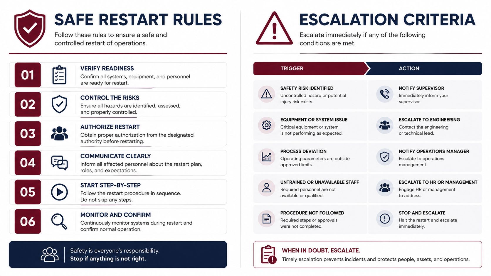
A controlled restart is appropriate only after the fault has been recorded, the immediate cause has been assessed, and the equipment is safe to energize. A reset isn't a diagnostic method. It's the final step after correction or a carefully bounded test.
Restart only when the risk is understood
A single trip with no visible damage, stable supply, normal cooling, and a plausible external cause may justify a controlled restart. Keep personnel clear of moving machinery, confirm permissives and safety circuits, and observe the drive during acceleration, steady operation, and stopping. Record the result rather than treating a successful run as proof that the problem has disappeared.
Don't restart after a burning smell, smoke, visible arcing, damaged terminals, repeated instantaneous overcurrent, unexplained ground fault, severe overheating, or evidence of internal flashover. Don't restart when the motor or machine can move unexpectedly, when stored mechanical energy hasn't been controlled, or when the protection event involves a safety circuit that hasn't been verified.
Choose repair, reconditioning, or replacement deliberately
Use the following escalation logic:
- Restart and monitor: The fault has a verified external cause, the installation is intact, and measurements are normal after correction.
- On-site diagnosis: The fault recurs under a specific load, temperature, vibration, or control condition, but the drive remains safe to test.
- Workshop repair: There is evidence of damaged power components, failed control boards, parameter corruption, or internal thermal damage requiring disassembly and bench testing.
- On-site reconditioning: The drive is large, difficult to transport, or operationally risky to remove, and serviceable subsystems can be renewed during a planned shutdown.
- Replacement assessment: Repair risk, parts availability, compatibility, remaining service life, and process requirements make renewal more practical than continued repair.
Medium- and high-voltage equipment deserves particular caution. Transport can introduce handling and storage risks, and removing a large drive can extend the outage. On-site reconditioning can address cooling assemblies, connections, control hardware, and other serviceable subsystems without automatically changing the whole unit.
Know when emergency support is justified
Call qualified drive specialists when the line is critical, the fault is recurring, the drive shows signs of internal damage, or the site lacks the instruments and personnel required for safe testing. A 24-hour response is valuable when the immediate objective is controlled recovery, but the service record should still capture the deeper follow-up work. Otherwise, emergency support restores production without preventing the next outage.
The practical trade-off is clear. A fast reset may recover motion, but a documented repair decision protects the asset and the next production run.
Networked Drives and Data-Driven Troubleshooting
Modern VFDs don't operate as isolated power converters. They exchange commands, status, feedback, safety signals, and diagnostic data with PLCs, fieldbus networks, remote panels, and condition-monitoring systems. A communication or feedback fault can therefore originate in shielding, signal quality, protocol configuration, firmware compatibility, a sensor, or the control logic rather than in the drive's power stage.
Start by separating command loss from drive protection. Did the drive stop because its own protection operated, or did it stop because an enable, run command, safety input, speed reference, or feedback signal disappeared? The display and fault history should be compared with the PLC event record and network status at the same time.
Test the signal path, not only the connector
Inspect cable routing near switching conductors, shield termination, connector condition, grounding arrangements, and physical strain. Check whether the network remains stable when the motor reaches the speed or load associated with the trip. Electrical noise may appear only while the inverter is switching under load, so a network that looks healthy while stopped isn't necessarily healthy in operation.
Confirm device identity, communication settings, timeout behavior, scaling, and feedback direction against the approved configuration. A parameter mismatch can produce a believable but incorrect feedback value, causing the drive or controller to respond as though the machine has a real process fault.
For plants building a broader monitoring architecture, industrial IoT monitoring guidance provides relevant context for connecting operating data with maintenance decisions. The value isn't in collecting every signal. It's in collecting the signals that distinguish a supply event, a thermal trend, a mechanical load change, and a communication interruption.
Build a correlated event record
Export fault history where the drive supports it. Combine drive temperature, output current, DC-bus behavior, speed reference, actual speed, feedback quality, network status, and cabinet conditions. Thermal images and inspection notes add physical evidence that a numerical log can't provide.
A useful diagnostic question is: which data stream changed first? If the network drops before the drive fault, investigate communications. If current rises before the trip, investigate load and motor circuit conditions. If temperature climbs gradually while current remains normal, investigate cooling and cabinet heat. If the DC bus changes during a stop, investigate regeneration and braking.
This approach prevents a common modern mistake, blaming every integrated fault on the drive because the drive happens to display the final alarm. Data should narrow the fault domain before technicians open the enclosure or order parts.
Your Complete VFD Troubleshooting Methodology
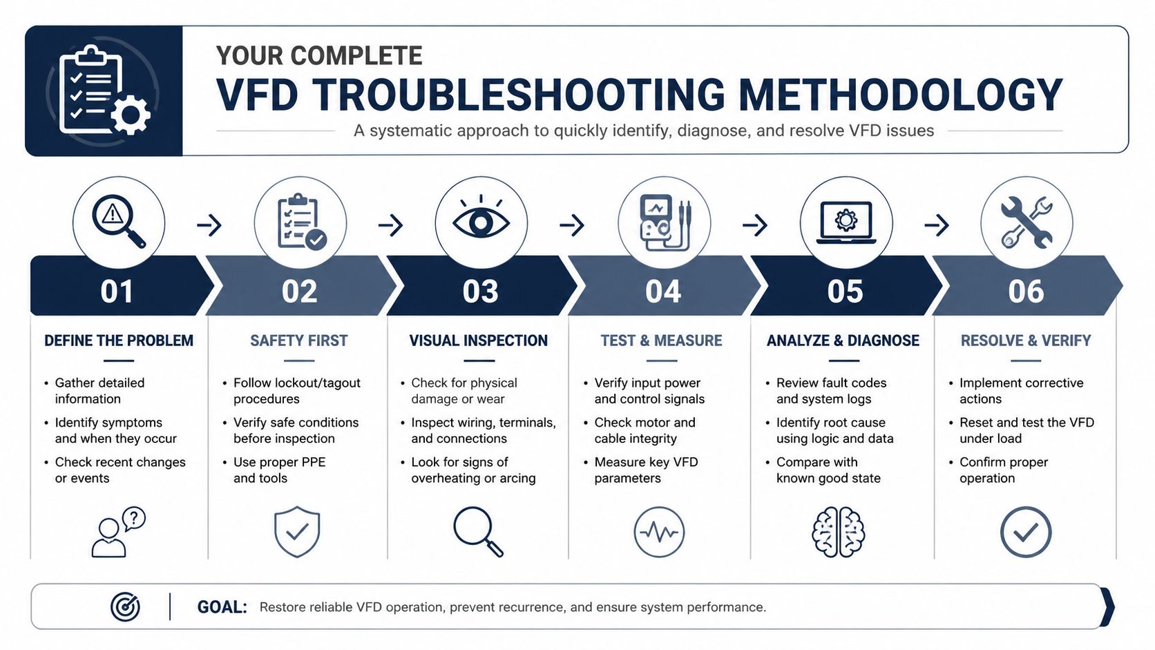
A repeatable method keeps a night-shift incident from becoming a recurring production problem.
- Capture evidence. Record the exact alarm, timing, operating state, recent changes, and fault history.
- Make the area safe. Apply the site's isolation and lockout procedures before inspection or testing.
- Inspect externally. Check contamination, moisture, cooling, terminals, supply condition, motor wiring, grounding, and the machine load.
- Verify settings and measurements. Compare motor data, ramps, limits, feedback, input balance, output balance, current, and DC-bus behavior.
- Reproduce carefully. Test under the condition that creates the fault, including heat soak, load, stopping, or communications activity.
- Escalate from evidence. Restart only after correction. Choose deep repair, on-site reconditioning, subsystem renewal, or replacement according to the demonstrated failure mode.
During planned shutdowns, prioritize cleaning, fan and filter checks, terminal inspection, thermal review, parameter backup, and spare-part compatibility checks. Progressive contamination and heat-driven aging rarely improve without intervention. Before dispatching a replacement or exchange unit, verify model, rating, firmware and control compatibility, accessories, and the required configuration.
For difficult failures, professional service should include disassembly where necessary, bench diagnostics, component-level repair, functional testing, and a documented return-to-service procedure. DUCHENG Industrial provides multi-brand VFD commissioning, preventive maintenance, troubleshooting, workshop repair, on-site reconditioning, spare-parts verification, and smart O&M support for industrial facilities. Contact DUCHENG Industrial with the drive model, fault history, operating conditions, and recent measurements so the response can begin with fault isolation rather than guesswork.