
Master equipment condition monitoring for VFDs and motors. Explore vibration, thermography, oil analysis, and IoT sensors to prevent unplanned downtime.
The most popular advice about equipment condition monitoring is also the least useful: install more sensors, collect more data, and reliability will improve. On a plant floor, that approach often creates a dashboard full of deviations while technicians still ask the same practical questions, What changed, how serious is it, and what should we do before the drive or motor trips?
Condition monitoring works when it connects a specific signal to a known failure mode, operating context, and maintenance decision. A vibration trend means little if nobody knows whether the machine was loaded, idling, misaligned, or recently serviced. A temperature alarm can be equally misleading if the system doesn't account for ambient heat, cabinet contamination, or a changed load profile.
The discipline has matured quickly. A 2026 systematic review of industrial maintenance literature identified 465 peer-reviewed studies on condition monitoring technologies published between 2001 and 2023, but only 42 met the review's eligibility criteria. That history shows both substantial development and a relatively small core of highly relevant evidence. For drives and motors, the lesson is straightforward: reliability teams need fewer disconnected signals and better decisions built around actual failure mechanisms.
Table of Contents
- Why More Sensors Do Not Guarantee Better Reliability
- Core Monitoring Techniques for Drives and Motors
- The Decision Gap Between Data Collection and Maintenance Action
- Continuous Online Monitoring Versus Periodic Route-Based Inspection
- Real-World Applications in Harsh Industrial Environments
- Building a Monitoring Program That Drives Real Decisions
- Connecting Condition Monitoring to Lifecycle Drive Services
Why More Sensors Do Not Guarantee Better Reliability
A sensor doesn't prevent a failure. It only observes a physical effect, and that effect becomes useful when someone can interpret it in context and act at the right time.
Many programs start with hardware. A team installs vibration, temperature, current, and environmental sensors across critical assets, then waits for the platform to reveal the answer. The trouble begins when the collected signals aren't tied to how each asset fails. A motor may experience bearing wear, shaft misalignment, cooling restriction, insulation degradation, or an electrical disturbance, but each condition leaves a different signature and develops on a different timescale.
The wrong question creates the wrong program
The practical question isn't, “Which sensors can we install?” It's, “Which signals can predict failure for this asset under its actual operating profile?”
A VFD-driven fan that changes speed throughout a production cycle doesn't produce one fixed definition of normal. Vibration, current, temperature, and fault-code data need to be interpreted against speed, load, acceleration, deceleration, and process demand. A reading captured while the motor is idle may be technically valid but operationally useless.
Harsh environments make the problem worse. Conductive dust, carbon black, salt-laden air, moisture, heat, and restricted airflow can alter cabinet temperature and accelerate aging without producing the same early warning as a mechanical bearing fault. If the monitoring program tracks only motor vibration, it can miss the drive's deteriorating cooling path or contamination-related electrical risk.
Practical rule: Every monitored signal should answer a maintenance question. If the team can't state the failure mode, decision, and response associated with a signal, the signal probably doesn't belong in the first deployment.
Reliability depends on context
A useful baseline includes the asset's normal speed range, load behavior, temperature environment, maintenance history, criticality, and known recurring faults. Without that context, threshold alerts identify difference rather than danger.
This is why “more data” can reduce trust. Technicians receive warnings that something has moved outside a limit, but they still need manual checks to determine whether the change is urgent, harmless, or caused by a process condition. The program then becomes an expensive notification layer over a reactive maintenance process.
The field is expanding into mainstream industrial practice. One 2026 market estimate for machine condition monitoring places the market at USD 1.4 billion in 2025, with a projection of USD 1.53 billion in 2026 and USD 2.41 billion by 2031. That growth reflects real adoption, but adoption alone doesn't prove that a program is decision-ready. Reliability improves only when collected information changes what people inspect, schedule, repair, or replace.
Core Monitoring Techniques for Drives and Motors
The right technique depends on the physical failure mode. Think of each method as listening to a different part of the machine's story. Vibration is the heartbeat, temperature is the fever, electrical signature is the load and supply behavior, lubricant analysis reveals internal wear, and continuous sensors provide the timeline.
Vibration analysis
Vibration is usually the starting point for rotating equipment because bearings, couplings, shafts, gears, looseness, imbalance, and misalignment affect how a machine moves. Analysts look at amplitude, frequency content, harmonics, phase, and changes from a trusted operating baseline.
On a motor connected to a VFD, speed matters. A variable-frequency drive changes the motor's electrical frequency and can change the mechanical response, so a fixed threshold may produce misleading alarms. Sampling should capture the machine while it operates at meaningful speeds and loads, not just during a convenient inspection window.
Thermography and temperature monitoring
Thermal inspection identifies hot connections, overloaded components, blocked cooling paths, bearing friction, poor ventilation, and abnormal cabinet conditions. For a drive, inspect power terminals, bus components where accessible, cooling fans, heat sinks, and enclosure airflow. For a motor, compare bearing housings, frame temperature, terminal boxes, and cooling surfaces.
Continuous temperature monitoring can reveal a gradual rise that a periodic infrared inspection might miss. It still needs context, because ambient temperature, production load, enclosure cleanliness, and recent process changes can all influence the reading.
Oil and lubricant analysis
Oil analysis suits gearboxes, hydraulic systems, and lubricated assemblies more directly than most standard motor bodies. It can reveal contamination, moisture, viscosity change, and wear particles. The value comes from trend interpretation and disciplined sampling, not from sending an occasional sample without recording operating conditions or lubricant history.
Electrical signature analysis
Electrical monitoring examines current, voltage, power, imbalance, harmonics, overload behavior, and drive fault records. It can help identify abnormal loading, supply disturbances, insulation concerns, motor degradation, and interactions between the drive, motor, and process.
For VFD systems, electrical data should be read alongside thermal and mechanical information. A current change might reflect a process upset, a mechanical restriction, a parameter change, or developing motor trouble. The signal points to a question, not automatically to a repair.
IoT-based continuous sensing
Connected sensors provide persistent data from assets that are critical, remote, inaccessible, or prone to fast-changing conditions. They can combine vibration, temperature, electrical values, operating states, and alarm history in a common workflow. The advantage is continuity. The risk is continuous noise if the system doesn't distinguish running, stopped, starting, and abnormal process states.
A practical overview of industrial IoT monitoring is useful when planning how sensor data should move from field devices into a maintenance process.
| Technique | Primary Failure Modes Detected | Best Suited For |
|---|---|---|
| Vibration analysis | Bearing wear, imbalance, misalignment, looseness, gear damage | Motors, pumps, fans, gearboxes, rotating trains |
| Thermography and temperature | Hot connections, cooling restrictions, friction, overload, electrical heating | VFD cabinets, motor frames, bearings, terminals |
| Oil and lubricant analysis | Contamination, moisture, viscosity change, internal wear | Gearboxes, hydraulics, lubricated mechanical systems |
| Electrical signature analysis | Abnormal load, imbalance, harmonics, supply disturbance, insulation concerns | Motors, VFDs, feeders, electrical panels |
| Continuous connected sensors | Changing trends, intermittent anomalies, combined mechanical and thermal behavior | Critical, remote, inaccessible, or variable-load assets |
No single technique covers every failure mode. Start with the dominant risks on each asset, then add another sensing method only when it closes a known diagnostic gap.
The Decision Gap Between Data Collection and Maintenance Action
A monitoring system can detect an anomaly without establishing its severity. That distinction explains why teams often hesitate after receiving an alert. They may know that a value changed, but not whether the machine has hours of safe operation remaining, needs inspection during the next planned stop, or should be removed from service.
False alarms intensify that hesitation. Recent research identifies false alarm rates as a core limitation in process-industry condition monitoring, especially where operating conditions change frequently. When warnings repeatedly fail to lead to meaningful action, technicians learn to wait for confirmation. The dashboard continues to work, but the maintenance behavior returns to reactive habits.
Why alarms lose credibility
A useful alert needs more than a limit violation. It should show:
- The affected asset: Identify the exact drive, motor, bearing location, cabinet, or circuit.
- The observed change: Show the trend, operating state, and comparison with a relevant baseline.
- The likely failure mode: Separate a possible bearing problem from a thermal or electrical condition.
- The urgency: Define whether the response is immediate, planned, or confirmatory.
- The next action: Specify inspection, measurement, cleaning, repair, parameter review, or controlled shutdown.
Missing information remains a major barrier. Recent industry reporting says missing sensor data, maintenance history, and spare-parts proximity was cited by 51% of respondents in a 2024 global survey discussing condition-based maintenance, as described in coverage of common condition monitoring failures. A warning without history or parts context forces the technician to rebuild the decision manually.
Human judgment still belongs in the loop
AI can help classify patterns, correlate multiple signals, and prioritize alerts, but maintenance teams still need explainable reasoning. A black-box warning that says “abnormal condition” doesn't tell an electrician whether to inspect cooling airflow, verify motor insulation, examine bearings, or review drive parameters.
This matters even more as interest in always-on monitoring grows. Eaton's 2025 survey reported that continuous thermal monitoring specification surged to 71%, according to the research discussion of false alarms and decision uncertainty. Continuous detection increases visibility, but it also increases the cost of poor thresholds. A team needs alert suppression for irrelevant states, severity rules tied to asset criticality, and a clear escalation path.
The useful alert isn't the loudest alert. It's the one that tells a technician what changed, why it matters, and what can be done next.
Review every alarm after resolution. Was the signal valid? Was the threshold too sensitive? Did the crew have the information and parts needed to respond? Those reviews turn monitoring from a notification service into a learning system.
Continuous Online Monitoring Versus Periodic Route-Based Inspection
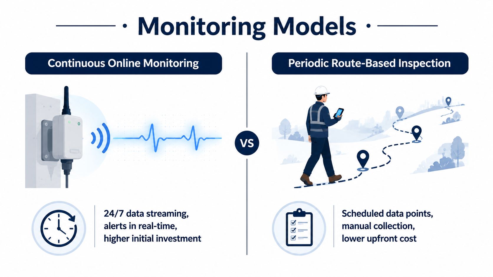
Continuous online monitoring and route-based inspection solve different problems. One provides persistent visibility and rapid detection. The other provides flexible human observation at a lower entry burden, often using existing maintenance rounds and specialist interpretation.
The choice should follow asset criticality, failure speed, accessibility, operating variability, and consequence of failure. A remote motor feeding a major process may justify online sensing because a developing fault can progress between rounds. A redundant auxiliary motor in an accessible area may be adequately covered by a disciplined route.
Where continuous monitoring fits
Online systems stream measurements while equipment runs. They suit assets with fast-changing conditions, difficult access, high production impact, or failure modes that may develop between inspections. They can also capture transient events, starts, trips, load changes, and thermal excursions that a scheduled route won't see.
The trade-off is real. Online deployment requires installation planning, reliable communications, sensor maintenance, data governance, and alert ownership. A plant that connects equipment without assigning response responsibility has created visibility, not control.
Where route-based inspection remains strong
Route programs work well when assets are accessible, operating conditions are stable, and failure progression allows time for the next planned inspection. A trained technician can combine vibration, infrared, sound, visual checks, lubrication observations, and operator feedback in one visit. That human context is difficult to reproduce with an isolated sensor.
The weakness is sampling. An intermittent machine may be inspected while stopped, a thermal problem may appear after the route, and a drive trip may erase the opportunity to observe the developing condition.
A hybrid model for VFD-heavy sites
VFD faults are often multi-causal. Thermal stress, contamination, aging, load changes, and electrical disturbances can interact, so a single deployment model rarely covers the full risk. Use online monitoring for critical drive temperatures, cabinet conditions, fault states, and operating trends. Use route inspections for airflow, dust accumulation, terminal condition, fan performance, grounding, visible damage, and corroborating measurements.
| Decision factor | Continuous online monitoring | Periodic route-based inspection |
|---|---|---|
| Data availability | Persistent readings and event capture | Scheduled observations |
| Response time | Rapid alerts when configured correctly | Depends on route frequency and access |
| Human involvement | More automated screening, planned response | High technician involvement during collection |
| Initial burden | Higher installation and integration effort | Lower hardware burden, stronger labor demand |
| Best use | Critical, remote, variable, or fast-changing assets | Accessible assets with stable operation |
The strongest programs don't treat these models as rivals. They reserve online monitoring for the failure modes and assets that need it, then use routes to verify conditions and catch physical problems sensors can't see.
Real-World Applications in Harsh Industrial Environments
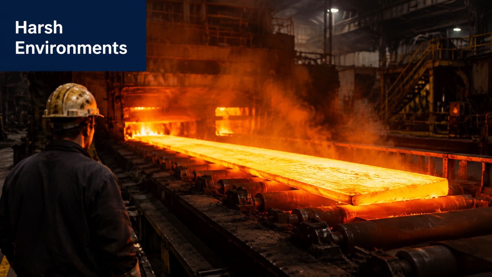
A steel plant motor doesn't fail in a laboratory. It fails beside heat, scale, vibration, dust, washdown, production changes, and a shutdown window that never seems long enough. Condition monitoring has value only when it fits those constraints.
Steel and metals
On a steel line, vibration trends can help maintenance teams identify developing bearing, coupling, or alignment problems before a planned outage. Thermal inspections during a shutdown can then check cabinet contamination, cooling paths, terminals, and drive components that may not reveal their full condition through mechanical data alone.
The important decision often comes before the repair. If a medium- or high-voltage drive shows rising thermal stress, repeated trips, or evidence of contamination, the team may need to choose between cleaning and preventive care, component-level repair, on-site reconditioning, or a larger upgrade assessment. Monitoring data gives that decision a documented starting point instead of relying only on the last failure.
Tire manufacturing and carbon black exposure
Carbon black contamination can settle inside cabinets and interfere with cooling and insulation clearances. A drive may continue operating while heat rejection worsens, then trip during a high-load production period. Temperature trends, fan status, enclosure inspections, and contamination findings should be reviewed together.
A periodic shutdown is the right time to clean, inspect, torque as appropriate, verify cooling performance, and record the post-maintenance baseline. If the drive is too large or risky to ship, on-site reconditioning can keep the work inside the planned outage instead of adding transport and workshop delays.
Chemical facilities and high-salinity environments
Chemical sites may expose electrical equipment to corrosive or conductive atmospheres, while access restrictions and process continuity make repeated manual checks difficult. Continuous thermal and electrical data can identify changes that deserve a controlled inspection, but the alert should lead to a defined field procedure, not an informal request to “take a look.”
At these sites, the maintenance record should include process state, enclosure condition, recent trips, cooling performance, and any environmental event that could explain a change. That context helps separate a genuine drive health issue from a temporary process disturbance.
The service workflow matters as much as the sensor. Commissioning checks establish the initial condition, route inspections verify the physical installation, shutdown maintenance addresses known stressors, and late-life data supports repair-versus-replacement planning.
A short visual explanation of industrial monitoring and maintenance workflow can help teams align operators, electricians, and reliability personnel before deployment.
<iframe width="100%" style="aspect-ratio: 16 / 9;" src="https://www.youtube.com/embed/UCRw8v_wQZE" frameborder="0" allow="autoplay; encrypted-media" allowfullscreen></iframe>Condition data also supports spare-parts planning. When a drive shows an approaching end-of-life risk, the team can verify compatible exchange units and critical components before the failure forces an emergency purchase.
Building a Monitoring Program That Drives Real Decisions
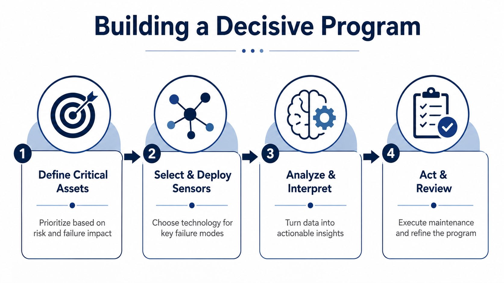
Start small, but start with the assets that can hurt production, safety, quality, or recovery time. A broad pilot across low-risk equipment creates data volume. A focused pilot on a critical drive or motor creates a test of whether the organization can detect, decide, and execute.
Define the decision before selecting the sensor
Rank assets by consequence and failure behavior. Then write the failure-mode map:
- Identify the failure: Bearing wear, misalignment, cooling restriction, contamination, insulation degradation, overload, or electrical disturbance.
- Name the observable signal: Vibration spectrum, temperature trend, current behavior, fault history, visual condition, lubricant evidence, or process state.
- Set the response: Confirm in the field, schedule during the next stop, reduce load, repair, recondition, or plan replacement.
- Assign ownership: Name the person or team responsible for reviewing, approving, and closing the action.
A practical guide to predictive maintenance for motors can support the failure-mode and workflow discussion, but your plant's own history must determine the final monitoring design.
Build a trustworthy baseline
Capture data under known operating states. Record speed, load, ambient conditions, recent work, process mode, and any unusual event. For VFDs, include acceleration and deceleration behavior, carrier-frequency considerations where relevant, cooling status, fault codes, and motor operating history.
Avoid setting alarms from a single reading. Establish normal ranges for meaningful operating states, then define warning and action thresholds with maintenance and operations together. A threshold that cannot be explained will not be trusted.
Connect alerts to work
An alert should create a maintenance task with the asset identity, evidence, recommended verification, urgency, and closure requirement. Sensor calibration, mounting condition, communications health, and data quality need routine ownership too. Bad data is not neutral. It consumes attention and makes good data harder to believe.
Review the program after every confirmed fault and every false alarm. Remove signals that never change a decision, add missing context, and adjust inspection routes where online data shows a recurring blind spot. The program becomes reliable when technicians see that their feedback changes the logic.
Connecting Condition Monitoring to Lifecycle Drive Services
Condition monitoring should follow the drive and motor through the lifecycle, not sit apart from commissioning, shutdown maintenance, troubleshooting, and repair. At start-up, baseline data can verify that installation, cooling, parameters, and operating behavior are acceptable. During production, trends and alarms can guide inspections before a trip becomes an outage.
During planned shutdowns, the team can combine monitoring history with physical checks for contamination, thermal stress, fan condition, terminals, insulation-related concerns, and mechanical alignment. After service, a new baseline confirms whether the work addressed the observed condition.
Late-life decisions also improve when the evidence is organized. A drive with recurring trips, worsening thermal behavior, and limited parts availability may justify an upgrade or replacement assessment. Another unit may be serviceable through component-level repair or on-site reconditioning, especially when shipping a large medium- or high-voltage drive creates operational risk.
That is the practical value of lifecycle integration. Equipment condition monitoring identifies what is changing, service teams determine what it means, and maintenance execution turns the finding into controlled action. Spare-parts identification, compatibility review, exchange-unit checks, and documented repair history complete the loop.
DUCHENG Industrial supports VFD lifecycle work with commissioning assistance, troubleshooting, preventive care, workshop repair, on-site medium- and high-voltage drive reconditioning, and monitoring architecture consulting. If your plant needs to connect condition data with inspections, repairs, alarms, and spare-parts planning, visit DUCHENG Industrial to discuss a practical approach for your drive and motor assets.