
Motor drive failure guide covering causes, symptoms, diagnostics and controlled recovery steps to restore uptime and decide when to call for help.
At 02:17, a conveyor motor stops, the operator sees a fault code, and production goes silent. The panel looks guilty, but the cause might be a loose supply connection, contaminated cooling path, damaged motor cable, excessive load, or a problem inside the drive itself. Resetting the alarm may restore motion briefly, or it may turn a warning into damaged power electronics and a longer outage.
A disciplined response starts by separating the fault layer before anyone replaces a board or orders a new unit. This guide follows that approach, from the first symptoms and operating conditions to safe isolation, controlled restart, lifecycle decisions, and professional support when the evidence points beyond a routine reset.
Table of Contents
- When Your Motor Drive Trips at the Worst Possible Moment
- How Motor Drives Work and What Failure Really Means
- Common Causes Behind Motor Drive Failure in Harsh Plants
- Recognizing Symptoms and Separating Drive Problems From System Problems
- Safe Diagnostic Methodology and Controlled Restart Steps
- From Rapid Recovery to Lasting Reliability With Real Examples
- Your Next Steps After Motor Drive Failure and When to Get Help
When Your Motor Drive Trips at the Worst Possible Moment
The night-shift electrician has a familiar problem. A motor drive trips while the line is loaded, the process is halfway through a batch, and several people are asking whether the drive can be restarted. The display offers a code, but not a complete diagnosis. A rushed reset feels productive because it takes seconds, yet it also erases useful evidence and can expose the motor, load, and drive to the same damaging condition again.
The first question shouldn't be “How fast can we get this running?” It should be “What was the system doing at the instant it stopped?” Acceleration, steady operation, deceleration, startup after maintenance, and a recent washdown each point toward different fault domains. The same alarm family can demand completely different checks depending on that context.
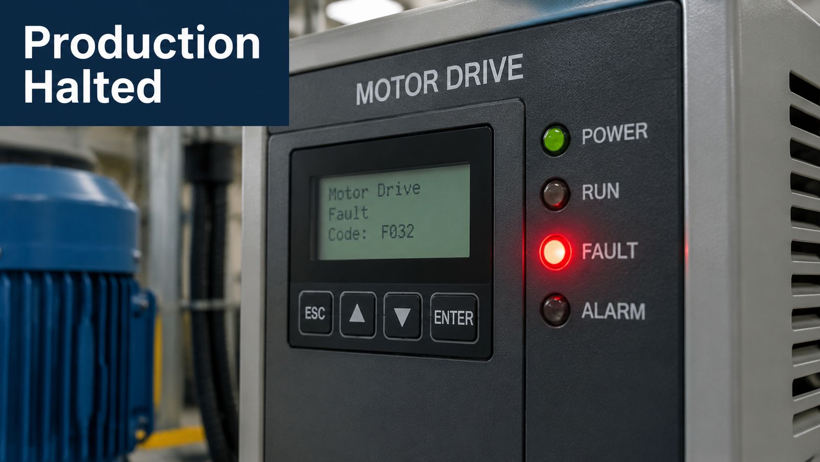
Why the first response matters
A motor drive is part of a chain, not an isolated box. The supply feeds the drive, the drive creates controlled output, the cable carries that output to the motor, and the motor delivers torque to a mechanical load. A failure anywhere in that chain can make the drive trip correctly.
Practical rule: Preserve the fault state before clearing it. Record the code, operating condition, frequency, current, DC bus voltage, recent work, and visible conditions around the cabinet.
Historical evidence supports treating the environment and maintenance process as serious suspects. A 2024 academic analysis of VFD power-module failures ranked dust accumulation as the largest contributing factor, with a 16.6% global priority share in its causal ranking; it also grouped old spare parts, high humidity, and lack of knowledge among the top four contributors (academic analysis of VFD power-module failures). That doesn't prove every trip is contamination-related, but it does explain why a clean fault log must be paired with an honest inspection of cabinet conditions and maintenance quality.
The method in this article is deliberately calm. Secure the area, capture evidence, isolate the drive from surrounding equipment where safe, test the simplest explanations first, and restart only when the evidence supports it. DUCHENG Industrial's lifecycle work fits into that broader model, with field diagnosis, workshop repair, preventive care, and on-site reconditioning used according to the asset's condition rather than a reflexive replacement decision.
How Motor Drives Work and What Failure Really Means
Think of a motor drive as a controlled power valve. It receives electrical energy from the plant supply, shapes that energy through a DC link and inverter stage, and sends the motor a controlled waveform. By adjusting output frequency and voltage, the drive manages speed, torque, acceleration, and braking.
That simple description reveals why a fault code isn't automatically proof of internal hardware failure. The drive is measuring a system that includes the incoming supply, its own power stage, the output cable, the motor insulation, grounding, feedback or control signals, and the mechanical load.
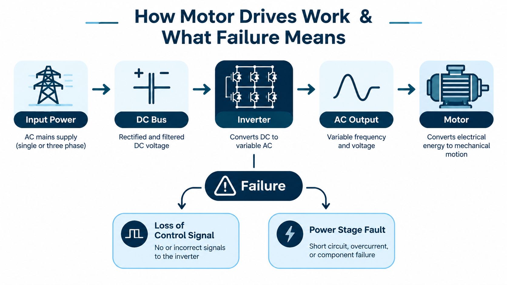
Follow the energy path
Start at the left side of the chain and work forward:
- Input power supplies the rectifier and charging circuit. Poor voltage balance, interruption, transients, or loose terminations can trigger protective action.
- The DC bus stores and stabilizes energy. Its voltage changes during acceleration, deceleration, and braking.
- The inverter switches semiconductor devices to create the commanded AC output. A genuine power-stage fault may appear here, but external faults can also make this stage trip.
- The motor circuit includes output terminals, cable insulation, shields, grounding, and the motor windings.
- The mechanical load determines how much torque and inertia the motor must handle. Binding, excessive friction, or an unsuitable ramp can create a perfectly valid overcurrent trip.
Failure, therefore, means the drive has detected a condition outside its safe operating envelope or has lost the ability to control power correctly. A protective trip can be evidence that the drive is working as designed.
Reliability measures need context
Reliability teams commonly compare drives using Mean Time To Fail, Mean Time Between Failures, probability of failure, PFH, and MTTFD, as described in a published discussion of AC variable-speed drive reliability (drive reliability measures and failure analysis). These measures help compare fleets and safety applications, but they don't identify the cause of today's trip.
The practical distinction is between a drive that has lost a power component and a drive that has correctly reacted to stress elsewhere. If the fault follows the motor when the motor is tested separately, investigate the motor, cable, load, or installation. If the fault remains with the motor disconnected, attention shifts toward the drive or its supply.
A trip is a message about system conditions. Treat the code as the beginning of the investigation, not the verdict.
Common Causes Behind Motor Drive Failure in Harsh Plants
Industrial cabinets often fail gradually before the display announces a problem. Dust settles on filters and heatsinks, humidity reaches terminals and boards, fans lose capacity, and heat accumulates inside an enclosure that appears normal from the outside. Each condition reduces the margin available to the drive's semiconductors, capacitors, control boards, and insulation systems.
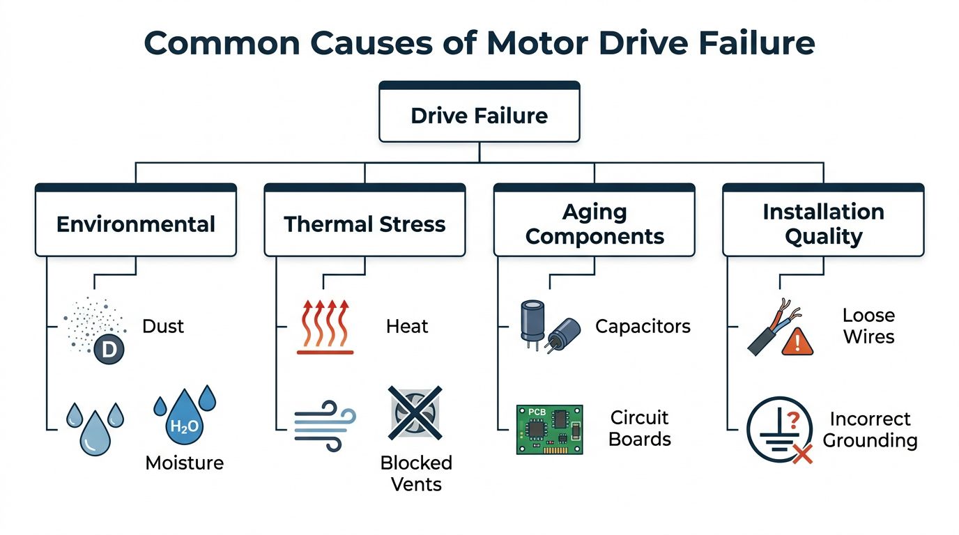
Contamination and heat work together
Dust isn't only a cleanliness issue. It can block airflow, coat heat-transfer surfaces, retain moisture, and create conductive or corrosive paths. High humidity and corrosive agents can accelerate deterioration around terminals and internal assemblies, especially in plants with frequent washdown, salt exposure, chemical vapors, or carbon black contamination.
Thermal stress often begins with a small restriction. A dirty filter forces the cooling system to work harder. A clogged heatsink cannot release heat efficiently. A failed fan leaves the power stage operating without its intended airflow. High ambient temperature then consumes the remaining margin.
Inspect these conditions during every suitable shutdown:
- Airflow paths: Check filters, heatsinks, fan operation, and the space around cabinet ventilation.
- Enclosure condition: Look for dust films, moisture marks, corrosion, degraded seals, and evidence of condensation.
- Terminations: Inspect for loose, discolored, oxidized, or overheated lugs, but follow isolation and manufacturer procedures before opening equipment.
- Grounding and shielding: Confirm bonding paths and cable shield practices match the installation design.
- Motor condition: Include insulation, bearings, and cable routes in the inspection, not only the drive cabinet.
Age and installation quality
Electrolytic capacitors dry out over years. Semiconductor packages can develop thermal micro-cracks, and repeated heating and cooling can weaken solder joints and connections. These mechanisms may produce intermittent trips before a complete failure, which is why a drive that “usually works” still deserves attention when its alarms become more frequent.
Installation quality creates a different pattern. Incorrect grounding, loose wiring, unsuitable cable routing, poor shielding, wrong parameters, and inadequate commissioning checks can stress a drive from its first operating period. The available guidance on early VFD failures attributes a large share to preventable installation and commissioning errors, and identifies overheating as a major reported failure category, but those claims should be treated as industry guidance rather than a universal plant rule (industry guide to drive fault codes and failure causes).
A hidden mechanism deserves special attention. VFD switching can create common-mode voltage and shaft current, allowing current to pass through motor bearings. Over time, that can produce electrical discharge machining pitting and bearing fluting while the drive itself continues to appear healthy. Grounding, shielding, motor insulation, and bearing condition belong in the maintenance plan together, not in separate checklists.
<iframe width="100%" style="aspect-ratio: 16 / 9;" src="https://www.youtube.com/embed/jJGtwkGJWEI" frameborder="0" allow="autoplay; encrypted-media" allowfullscreen></iframe>Recognizing Symptoms and Separating Drive Problems From System Problems
The operating state at the instant of the trip is often more informative than the alarm label. A drive that trips while accelerating is dealing with changing torque demand and current. A drive that trips after reaching stable speed presents a different diagnostic picture, where supply quality, insulation, grounding, cooling, and internal electronics deserve closer attention.
Use the following matrix as a first filter, not a substitute for the drive manual or site safety procedure.
Trip State Versus Likely Fault Domain
| Trip Condition | Most Likely Domain | First Checks |
|---|---|---|
| Trip during acceleration | Load inertia, ramp settings, torque or current limits, motor or cable condition | Review acceleration ramp, mechanical binding, output current, motor data, and cable insulation |
| Trip during deceleration | Braking circuit, excessive regenerative energy, ramp settings, high-inertia load | Review deceleration ramp, braking hardware, DC bus trend, and mechanical load |
| Trip at steady speed | Input power, grounding, motor or cable insulation, cooling, internal electronics | Check supply condition, terminations, temperature, airflow, insulation, and fault history |
| Overcurrent at startup | Motor circuit, incorrect parameters, mechanical resistance, output stage | Isolate the motor circuit where permitted, verify motor data, inspect cable and load |
| Overvoltage during slowing | Regeneration, braking path, supply condition, or excessive deceleration demand | Check braking path, DC bus behavior, ramp, and incoming supply |
| Undervoltage | Supply interruption, phase problem, loose connection, or DC-link charging issue | Verify incoming voltage, fuses, lugs, phase condition, and DC bus charging |
| Ground fault | Motor insulation, cable damage, moisture, grounding path, or output stage | Inspect cable route, motor insulation, moisture, and grounding before repeated resets |
| Communication loss | Control wiring, network path, EMI, power to control devices, or configuration | Check connectors, shielding, control power, parameter records, and communication history |
The field guidance behind this approach recommends recording the fault code, output frequency, output current, and DC bus voltage at the moment of the trip, then retesting with the motor disconnected when the procedure and equipment design make that safe (practical VFD troubleshooting guide). If the fault remains with the motor disconnected, the drive or its supply becomes more likely. If the fault clears, investigate the motor and cabling before condemning the drive.
Read patterns, not isolated alarms
A single overcurrent trip during acceleration may reflect a heavy load or an aggressive ramp. Repeated overcurrent at a stable operating point suggests a different problem. A ground fault after washdown points the team toward moisture and insulation, while a random communication loss points toward control wiring, shielding, or interference.
Don't swap a power board because the drive reported overcurrent. First ask whether the output current, DC bus voltage, motor insulation, cable condition, and mechanical resistance support that conclusion. This habit reduces false part changes and keeps the corrective action aligned with the damaged layer.
Safe Diagnostic Methodology and Controlled Restart Steps
The first hour should produce evidence, not guesses. Safety comes before measurement. Follow site isolation, discharge, arc-flash, and manufacturer requirements, and use qualified personnel for energized testing or internal access.
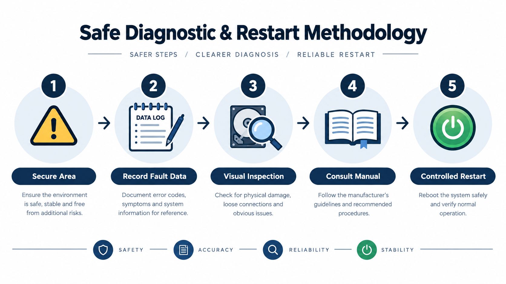
Secure and document
Begin by protecting people and the process. Confirm that the stopped equipment can't move unexpectedly, isolate stored mechanical energy, and communicate the work boundary to operations. Don't clear the alarm until the team has captured the available history.
Write down:
- Fault information: Code, subcode, sequence, and whether the alarm is active or historical.
- Operating state: Acceleration, steady speed, deceleration, startup, load change, or communication event.
- Electrical values: Output frequency, output current, DC bus voltage, and available input measurements.
- Recent changes: Maintenance, rewiring, motor replacement, parameter changes, washdown, process alteration, or cabinet relocation.
- Physical evidence: Heat marks, odor, fan condition, blocked airflow, moisture, dust, corrosion, loose hardware, and cable damage.
The first steps after a drive trip should remain aligned with the specific equipment manual and the site's electrical safety process. A written record also helps the next technician avoid repeating checks that have already been completed.
Isolate the fault layer
After the visual inspection, verify the supply, grounding, cooling path, and motor circuit in a controlled sequence. The motor-disconnected test is especially useful when permitted by the equipment design. If the same fault appears without the motor connected, investigate the drive and incoming supply. If it disappears, focus on the motor, cable, insulation, grounding, or load.
Don't use a megohmmeter or other test instrument without confirming that the drive, motor, filters, and connected electronics can safely tolerate the test. Incorrect testing can damage components or create a misleading result.
Restart condition: A controlled restart is justified only when the immediate cause has been checked, the area is safe, the drive has no evidence of active hardware damage, and someone is ready to monitor current, voltage, temperature, speed, and renewed alarms.
Restart under observation
Restore the system at the lowest practical risk. Remove unnecessary load if the process allows it, start with conservative settings approved for the application, and watch the measured values rather than relying only on rotation. Stop again if the fault returns, current rises abnormally, temperature increases quickly, vibration appears, or the original alarm changes into a more severe condition.
A restart that works isn't proof of a repair. It may only mean the fault condition has temporarily disappeared. Record the result, preserve the trend, and schedule a deeper inspection if the event was unexplained or recurring.
From Rapid Recovery to Lasting Reliability With Real Examples
Short-term recovery and long-term reliability require different decisions. A plant may need a controlled restart to protect production, then a planned shutdown to correct the condition that caused the trip. Treating the restart as the finish is how intermittent faults become repeat outages.
Example one, airflow restoration
A drive trips during a hot production period. The code suggests an overtemperature condition, but the technician finds a loaded filter and a heatsink coated with dust. After safe cleaning, fan verification, and a check of cabinet temperature, the drive may return to service under observation.
That response is appropriate only if the inspection rules out damaged components and confirms that the cooling path was the actual constraint. The preventive action is not “clean the cabinet.” It should identify cleaning frequency, filter condition, fan replacement criteria, enclosure sealing, and the person responsible for verification.
Example two, recurring electrical trips
Another drive trips at steady speed, then runs after a reset. The team records the event and finds unstable supply indications and a discolored termination. Tightening or replacing a connection without checking the upstream circuit may leave the underlying problem in place. The lasting fix requires verifying the supply path, grounding, cable insulation, and drive history together.
Trend data can help distinguish a single event from degradation. One established maintenance guide recommends baseline trending and investigating deviations of approximately 10% to 20% (VFD diagnosis and replacement guide). Use that as an investigation trigger, not a universal failure limit. The right baseline depends on the drive, process, measurement point, and operating state.
Example three, late-life medium-voltage equipment
A large drive may still power the process but show increasing thermal alarms, aging capacitors, or repeated cooling issues. Shipping the complete unit can introduce handling risk and extend the outage, especially when the asset is difficult to remove. In that situation, a plant may compare several paths:
- Rapid Restore: On-site fault isolation and a controlled return to operation.
- Deep Repair: Workshop disassembly, component-level repair, bench diagnostics, and functional testing.
- On-site Blue Reconditioning: Full reconditioning of a medium- or high-voltage drive during a planned shutdown when transport is impractical.
- Subsystem renewal: Replace serviceable fans, capacitors, control assemblies, or power sections after compatibility and condition checks.
- Whole-unit replacement: Choose this when supportability, damage extent, or the required future architecture makes repair unsuitable.
The decision should account for evidence, parts availability, electrical condition, shutdown access, and the risk of repeating the original stress. A faster replacement isn't automatically the safer lifecycle choice.
Your Next Steps After Motor Drive Failure and When to Get Help
After a motor drive trip, keep the response simple:
- Preserve the evidence. Record the code, operating state, electrical values, recent changes, and cabinet conditions.
- Identify the likely layer. Separate input power, drive electronics, motor cable, motor insulation, grounding, control signals, and mechanical load.
- Test safely. Use isolation and motor-disconnected checks only when qualified personnel and the equipment procedure permit them.
- Restart with conditions. Monitor the first return to service, and don't treat a successful reset as proof that the underlying fault is gone.
- Plan the durable correction. Address contamination, airflow, connections, insulation, bearing condition, aging components, parameters, and spare-part compatibility during the next suitable window.
Call for professional support when the fault returns, the drive shows signs of internal damage, the supply or insulation condition is uncertain, the equipment is medium or high voltage, or the plant can't safely perform the isolation tests. Workshop repair may suit a removable unit with localized damage. On-site reconditioning may suit a large late-life asset where transport creates additional risk. Replacement becomes a strategic decision only after condition, supportability, compatibility, and outage constraints are understood.
For teams evaluating that path, variable-frequency drive repair services can provide a reference point for comparing diagnosis, repair, reconditioning, and lifecycle support rather than jumping directly to changeout.
A reliable maintenance program also keeps a fault history, verifies spare parts before dispatch, inspects cooling and contamination during shutdowns, and trends meaningful electrical and thermal values against a plant-specific baseline. That preparation turns the next trip from a midnight guessing exercise into a controlled decision.
DUCHENG Industrial supports motor drive recovery with structured on-site diagnosis, workshop deep repair, preventive care, spare-parts compatibility checks, and on-site reconditioning for medium- and high-voltage assets. If your plant needs to separate a true drive hardware fault from a surrounding system problem, visit DUCHENG Industrial to discuss the next diagnostic or recovery step.