
Learn how to diagnose PLC repair faults, check I/O and power, verify backups and security, and decide between repair and replacement.
The machine has stopped halfway through its sequence. The operator wants a reset, production wants a restart time, and someone has already brought a spare CPU to the cabinet. The controller might be faulty, but a missing sensor signal, unstable supply or blocked interlock can produce the same stopped machine.
Good PLC repair starts by preserving evidence, then finding exactly where the expected signal or action stops. The job isn't finished when the RUN light returns. You also need a trustworthy program, compatible hardware and a restart record that explains why the equipment is safe to release.
Table of Contents
- What to Record Before Touching a Failed PLC
- How to Isolate a PLC Fault Step by Step
- Symptom, Cause and Fix for Common PLC Failures
- Power and Cabinet Checks Before Blaming the CPU
- Backups and Security Checks Before Restart
- Repair, Refurbish or Replace the PLC and Close the Job
What to Record Before Touching a Failed PLC
Someone cycles the power, the machine runs briefly, and the original fault disappears from view. You've now lost the fault state, possibly part of the event history, and the chance to establish which forces or program changes were present before the reset. Don't make that your opening move.
Photograph the CPU and I/O indicators, HMI alarm list and mode-switch position. Export the controller's diagnostic buffer or fault log before clearing anything, where the equipment's condition permits safe access. Record the operating step, product condition and what the operator did immediately before the stop.
Capture the state before changing it
Status indicators and what they usually mean
LED names, colors and flash patterns differ by controller. Treat these as starting points, then confirm their meaning against the module manual.
| Indicator | Typical state | Likely meaning | First check |
|---|---|---|---|
| CPU RUN | Off, STOP steady | Controller halted or in stop mode | Confirm mode switch and last stop reason in the diagnostic buffer |
| CPU ERROR or FAULT | Solid red | Hardware or fatal runtime fault | Read the diagnostic buffer and module error codes |
| Power LED | Off | No supply to the rack or power module | Check input voltage, fuse and main breaker |
| Input LED | On, but logic shows zero | Image-table mismatch or active force | Check forced inputs and compare with the field signal |
| Output LED | Off, but load expects ON | Output not driven or program condition | Compare output image and terminal voltage |
| Communication LED | Blinking or off | Possible network or configuration fault | Check cable, node address and module configuration; blinking may indicate normal traffic |
Record the last program or firmware change, who authorized it and when it occurred. A fault immediately after a download directs attention toward configuration and logic, although timing alone doesn't prove the cause.
This capture isn't administrative delay. According to MaintainX's industrial maintenance survey, reported by Maintworld, the average cost of an hour of unplanned downtime in 2024 was approximately $25,000, while large organizations reported costs exceeding $500,000 per hour.
Before anyone energizes the cabinet, write down the machine's safe state, stored-energy hazards and which interlocks remain active. Make the person controlling the restart explicit.
How to Isolate a PLC Fault Step by Step
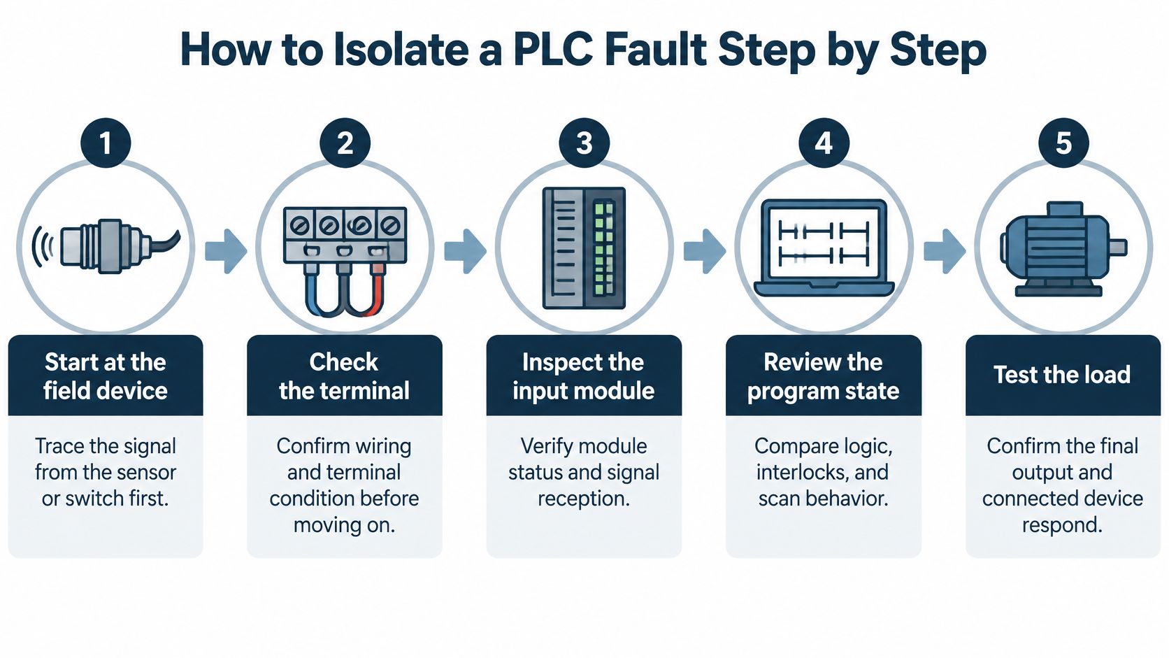
Follow the signal from the field device through its terminal, input module and program state to the final load. Random probing produces readings without establishing what they mean. A useful test identifies the boundary between something working and something not working.
Make the equipment safe before opening or disturbing connections. Apply the site's hazardous-energy controls, verify isolation for de-energized work, and reserve necessary energized measurements for qualified personnel using authorized procedures and correctly rated instruments. Treat a stopped CPU as a logic state, not as isolation.
Use this signal path to keep the investigation focused.
Follow the electrical evidence
-
Verify incoming and control power under load. Measure at the supply terminals and at the affected rack or field circuit while the machine attempts the failed action, because an idle reading can conceal a voltage drop. Common slip: measuring at the supply but never checking the voltage reaching the module.
-
Inspect fuses and safety permissives. Check emergency-stop status, guard circuits, safety-relay feedback and operating interlocks against the drawings, since an open permissive can correctly prevent an output. Common slip: bridging an interlock to prove a theory instead of diagnosing why it isn't satisfied.
-
Compare the physical input, channel LED and input image. Verify sensor operation, measure the signal against its correct common, then compare the module indication with the addressed program tag. Common slip: using a continuity function on an energized circuit; isolate and verify absence of voltage before continuity testing.
-
Trace the output decision in the program. Use cross-references to inspect permissives, sequence steps, timers, latched bits and active forces rather than changing a rung merely because it appears false. Common slip: overlooking another write to the same tag or leaving a temporary force enabled.
-
Compare the output command with the load response. Check the output image, channel indication, terminal voltage, field wiring and actuator in order to identify where the command stops becoming a physical action. Common slip: condemning the module before checking its separate field supply, fuse or load common.
For typical 24 VDC discrete I/O, an active point should measure close to the supply rail relative to its reference common, and an inactive point near zero. Thresholds differ between module families, so confirm the rated on and off levels, the polarity and the sourcing or sinking arrangement against the hardware documentation before you read anything into the meter.
Establish the repair boundary
For example, if the program commands a solenoid and the channel indicator is on, but voltage is missing downstream of a fuse, replacing the output card won't restore that circuit. Record the readings that establish that boundary. Apply the same industrial electrical troubleshooting discipline to contactors, drive enables and auxiliary circuits.
The boundary also frames what happens next. A fault traced to wiring or a field device is a targeted repair; a fault traced to the CPU, the backplane or a failed module raises the repair-versus-replace question and the lifecycle risk that comes with it. I treat an unexplained program state the same way. A force nobody enabled or a configuration that drifted is a trust problem, and it deserves scrutiny before restart, not after.
A healthy result means the complete production sequence runs, alarms reset correctly, and interlocks trip and reset as intended. Remove every temporary force and test connection, then retain the before-and-after evidence.
Symptom, Cause and Fix for Common PLC Failures
A dead CPU with no LEDs is a power-path investigation before it's a processor replacement. Start with what the operator can observe, not the component someone suspects. The distinction prevents a stopped conveyor from becoming a CPU fault on the work order without evidence.
The table gives practical starting hypotheses, not guaranteed diagnoses. Before disturbing a module, isolate the relevant energy sources and check whether the manufacturer permits the intended removal procedure.
Match the symptom to a discriminating test
Common PLC symptoms, causes and fixes
| Symptom | Likely cause | Fix |
|---|---|---|
| CPU dead, no LEDs | Blown fuse or failed power supply | Measure supply output under load; replace the failed fuse or power module with a matched part after correcting the cause |
| Intermittent input | Loose terminal or corroded connector | Isolate, inspect for heat discoloration, tighten to specified torque and clean or replace affected contacts |
| Output stays on | Welded relay contact or shorted transistor output | Isolate the load, test the channel and replace the output module if it fails |
| One input dead, others healthy | Failed sensor or broken wire | Verify the sensor signal at the terminal, then check wire continuity with power off |
| Whole I/O rack dead | Bus connector or backplane fault | Verify rack power first, then safely reseat modules, check bus cable and inspect the backplane |
| Module error only after a swap | Wrong firmware or hardware revision | Check catalogue number and firmware compatibility before reinstalling |
| Network device lost | Duplicate address or bad cable | Check node address, switch port and cable, then retest communication |
| Battery warning after power cycle | Backup battery depleted | Follow the approved battery-replacement procedure and verify retained data and clock settings |
An output that stays energized deserves immediate control of the physical hazard. Check whether another circuit is feeding the load before concluding that the output semiconductor or relay contact has failed. A program indication alone doesn't prove the terminal's electrical state.
For a missing network device, establish whether only that device is absent or the entire segment is affected. Protocol-specific checks, such as those in our legacy PLC serial communication guide, help separate addressing and configuration errors from defective hardware.
Replacement rule: Match the catalogue number and verify supported firmware, hardware revision, channel type and communication compatibility. A module that fits the slot isn't necessarily a functional substitute.
Our spare-parts process includes identification, compatibility review, sourcing for current and legacy equipment, and pre-dispatch checks. We also coordinate replacement or exchange, failed-part return and repair, with traceable service and logistics records.
If the symptom doesn't fit a clear fault boundary, don't keep swapping cards. Investigate the supply and cabinet conditions before sacrificing another replacement.
Power and Cabinet Checks Before Blaming the CPU
Processor-like symptoms can originate in the power architecture, cabinet environment or grounding. Don't assume the CPU is defective because it stops executing. Start with the conditions that allow it to operate reliably.
A published PLC reliability study reports failure rates below 0.025 failures per year for established industrial controllers under its assumptions, while identifying processor hardware, control software and power supply as key failure dependencies. That's a reason to investigate the supply, not a guarantee about the controller in your cabinet.
Measure under the conditions that trigger the fault
Check the control supply while outputs switch and connected devices draw current. Compare voltage at the supply and controller terminals against the manufacturer's permitted operating range. Don't impose a generic tolerance on equipment with different specifications.
Check ripple using an oscilloscope or a meter with suitable AC measurement capability and bandwidth. A rising AC component as the supply heats or takes load warrants investigation; an ordinary voltage display may conceal short disturbances. Use appropriate probes and safe measurement methods.
Inspect terminals for darkened insulation, heat discoloration and movement. With the circuit isolated, verify connections against the specified torque rather than tightening everything indiscriminately.
Inspect the operating environment
Use the cabinet's actual closed-door operating condition, not the cooled condition after maintenance has left it open.
- Temperature: Compare the measured cabinet temperature with the controller's rated ambient range and inspect fans, filters and blocked airflow.
- Contamination: Look for conductive dust, moisture, corrosion and deposits bridging terminals or circuit-board surfaces.
- Vibration: Check mounting security, connectors and cable strain near moving machinery.
- Grounding: Inspect the protective bonding path and signal-reference arrangements against the drawings; don't improvise connections between isolated commons.
A fault that appears when a motor starts calls for time-correlated investigation of supply disturbances, bonding and cable routing. It doesn't justify adding a ground wire at random. Record whether the cabinet door was open or closed when the event occurred.
A clean restart proves that the controller can run now. It doesn't prove that the intermittent cause has been removed.
Log the failure mode, downtime, repair time, affected channel, environmental conditions and replaced part. Those records distinguish isolated failures from recurring supply, wiring or thermal problems. Require a monitored operating period that includes the process conditions associated with the original fault before closing the investigation.
Backups and Security Checks Before Restart
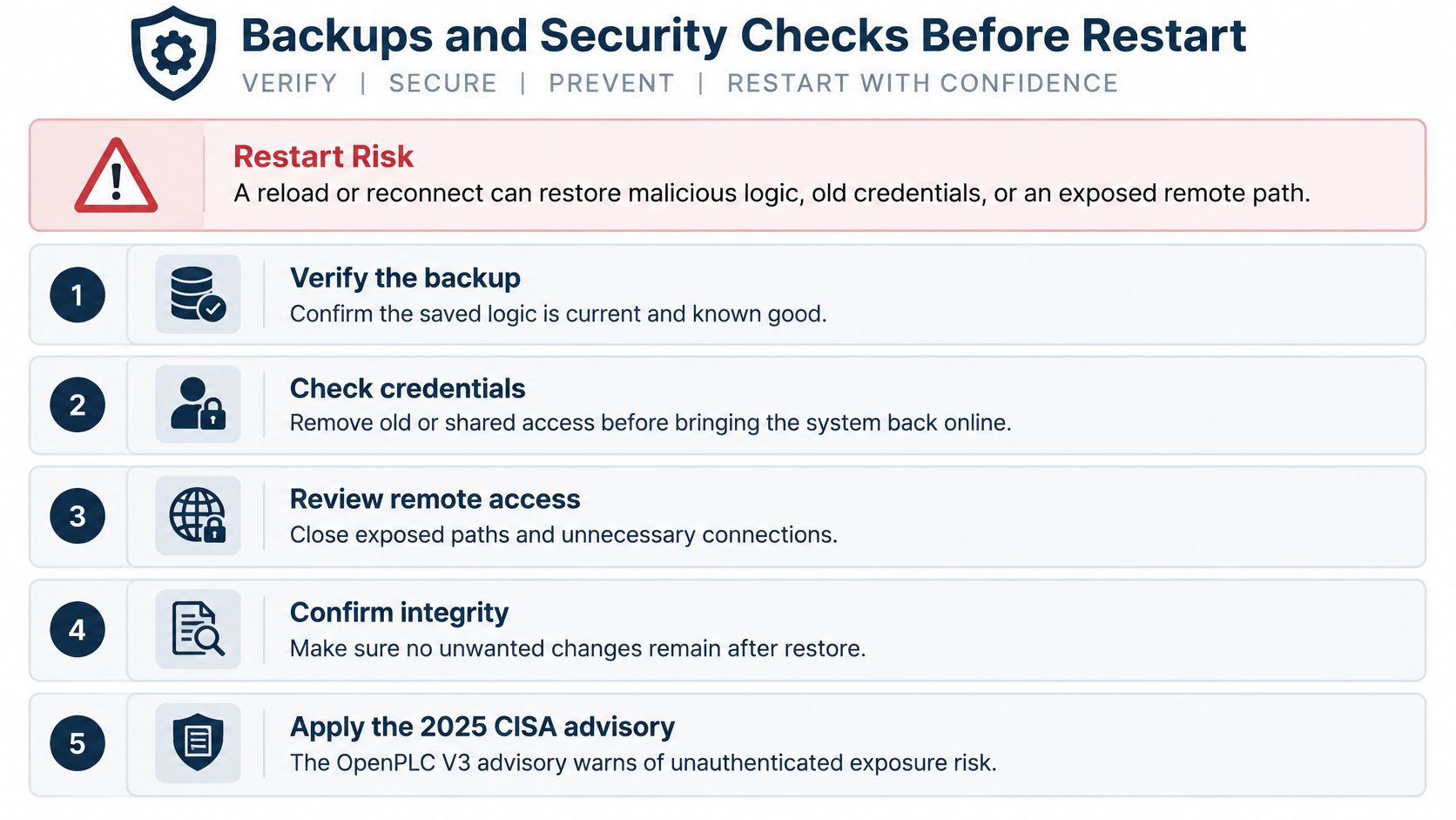
Reloading a program or reconnecting a controller can restore malicious logic, compromised credentials or an exposed remote-access path. Treat availability as one acceptance criterion; the recovered configuration also has to match a state the plant has approved.
The CISA OpenPLC V3 advisory reported a 2025 vulnerability that could enable unauthenticated denial of service against the runtime. That advisory leaves your diagnosis open, and it shows why a runtime fault deserves a software and exposure check before hardware is blamed.
Use the visual checklist as a restart reminder, then confirm whether an advisory applies to your equipment.
Establish a trustworthy recovery state
-
Isolate and preserve. Coordinate network isolation with operations so communication loss cannot create an unsafe process condition. Preserve logs and memory images where feasible before overwriting evidence; export the controller event log and HMI alarm history to CSV, then copy them to read-only storage.
-
Compare with the approved baseline. Check running logic, firmware and configuration against an authorized copy held outside the affected plant network. On the engineering station, open the last approved project archive and compare program blocks, firmware revision and communication settings against the running values. Escalate unexplained differences instead of normalizing them through a fresh download.
-
Validate the backup. Confirm its date, version, checksum where available, and approval record. A recent file is only a candidate until its checksum matches the approved copy.
-
Review remote access. Examine enabled remote connections, VPN access and engineering laptops that connected to the equipment. List active VPN users and remove any contractor account left enabled after the last outage through controlled changes, with each removal recorded.
-
Replace unsafe credentials. Rotate default, shared or potentially compromised credentials in coordination with dependent applications. Change the shared service password first, then verify the SCADA historian still logs in with its own account.
-
Verify segmentation. Check the actual permitted paths between the control segment, business network and remote users. From the business VLAN, confirm the engineering port is denied while the maintenance VLAN remains permitted for approved stations.
-
Document compensating controls. If patching is not feasible, record isolation, access restrictions, monitoring, the responsible owner and a review date. Tie the risk to an owner and a calendar reminder, with the expiry condition written down.
Legacy industrial protocols may lack built-in authentication. In that situation, network boundaries and access restrictions must provide protection the protocol itself doesn't supply.
Keep recovery records usable
A DUCHENG workshop handover includes intake and fault-diagnosis records, repair notes and replaced components, test records, relevant program or parameter documentation, and recommended next maintenance. File those records with the approved recovery package so future technicians can separate authorized repair changes from unexplained differences.
A restart that restores availability without restoring trust is not a successful repair. If integrity remains uncertain, involve the plant's OT security and controls owners before reconnecting normal production access.
Repair, Refurbish or Replace the PLC and Close the Job
Choose the route that controls the combined risk of downtime, lost configuration, unsupported hardware, safety dependencies and commissioning errors. The cheapest invoice can still leave the plant with the weakest recovery position.
Put the failure report beside the spare-module and backup records before committing. A module that bench-tests good can still be the wrong answer when its firmware is unsupported, the program backup is unverified, or the original fault traces back to power quality that will take out the replacement the same way.

CISA-related industrial vulnerability reporting highlights the operational difficulty of patching or replacing legacy equipment in live environments. Replacement therefore needs engineering and outage planning, not just a purchase order. A rushed migration can introduce undocumented logic changes, new network exposure and commissioning errors.
Score the route before committing
Use a simple internal readiness score from one to five, with the low end meaning unresolved or unacceptable and the high end meaning verified and manageable. Treat it as a decision aid for your own review board rather than an industry certification. Score each candidate route against these criteria:
- Fault criticality: Can the route address the consequence of failure, not merely restore operation?
- Tested spares: Are compatible, functionally checked modules available?
- Backup quality: Is the recovery package complete, approved and usable?
- Compatibility: Are firmware, hardware and communications supported together?
- Time to restore: Can diagnosis, installation and validation fit the outage?
- Safety dependencies: Can affected protective functions be verified?
- Vendor support: Can the plant obtain documentation, parts and necessary engineering access?
- Outage exposure: Does a controlled intervention reduce the consequence of another emergency failure?
Weight the safety, backup-quality and tested-spares criteria as gates rather than letting a strong total average them out. A poor backup score or missing tested spare should trigger staged-replacement planning instead of another indefinite cycle of emergency repair. Immediate recovery may still require a controlled interim solution while that plan is built.
Select the route that fits the evidence
Repair, refurbish or replace by situation
| Route | Best when | Main risk |
|---|---|---|
| Component-level repair | Single failed module, tested spare available, program backup verified | Repeat failures if the root cause is power, heat or wiring |
| Workshop repair of module or CPU | Faulty module can be shipped and bench-tested within the outage window | Transit time and no spare running in the meantime |
| Temporary substitute | Restart needed while a spare or planned outage is pending | Unreviewed logic, compatibility gaps and new network exposure |
| Program migration and staged replacement | Firmware or hardware is obsolete and backups are verified | Undocumented logic changes and commissioning errors |
| Full controller replacement | Obsolescence, no tested spare and repeated failures on the same platform | Largest outage and cutover risk, requiring a planned window |
Documented component repair with isolation and monitoring can be the lower-risk immediate choice. Repeated repairs without an obsolescence plan leave the plant dependent on equipment it may no longer be able to restore.
Use the following video alongside the written assessment, not instead of an equipment-specific restart plan.
<iframe width="100%" style="aspect-ratio: 16 / 9;" src="https://www.youtube.com/embed/StVWUyTUuqE" frameborder="0" allow="autoplay; encrypted-media" allowfullscreen></iframe>Close with an accountable release
The written release should name the confirmed fault boundary, the corrective actions performed, the restart and functional-check results, and the open risks with follow-up recommendations. Assign an owner and a review date to every unresolved item. Where production accepts the restart while an engineering or security condition remains open, keep that condition on the record until it is closed.
File the release with the recovery records assembled under the backup and security checks, so the next technician can separate authorized repair changes from unexplained differences. The job is closed when every open risk has an owner or a resolution, which goes further than getting the outputs back on.
DUCHENG Industrial offers structured fault diagnosis, workshop repair for drive and automation equipment, spare-part compatibility review and controlled restart support. Visit DUCHENG Industrial with your equipment model, fault records, operating symptoms and available backup details so we can review the repair scope and appropriate recovery route.