
Master RS485 RTU Modbus wiring, addressing, baud settings, and diagnostics. Learn how to integrate VFDs and SCADA systems with proven industrial practices.
The new VFD is mounted, powered, and parameterized. The motor runs from the keypad, but the SCADA master shows a timeout, and the production team is asking why a two-wire connection has become the problem. In a brownfield plant, that situation is common. The drive may have the wrong server address, the RS485 pair may be reversed, a termination switch may be enabled in the middle of the trunk, or the master may be polling faster than the devices can answer.
RS485 RTU Modbus works well because it keeps the physical network simple. It can connect drives, meters, remote I/O, and controllers over a shared serial bus without adding an Ethernet switch to every cabinet. It also has limits that become more visible as the network grows. The sections below treat the link as two systems that must agree, the RS485 electrical layer and the Modbus RTU transaction layer, then apply that distinction to wiring, commissioning, SCADA integration, scalability, security, and fault isolation.
Table of Contents
- Why RS485 RTU Modbus Still Runs the Plant Floor
- Understanding the RS485 Physical Layer and Modbus RTU Frames
- Wiring the Bus for Reliable Communication
- Configuring Addresses Baud Rates and Timing
- Integrating VFDs and Plant SCADA Systems
- Security and Scalability Limits You Cannot Ignore
- Diagnosing Common Field Failures and Communication Drops
Why RS485 RTU Modbus Still Runs the Plant Floor
A drive can run perfectly from its keypad while the SCADA screen reports repeated timeouts. In a brownfield cabinet, that symptom rarely identifies one failed component. Local operation confirms that the power section and basic control are available. It does not confirm that the communication option is enabled, the serial port uses RTU mode, the master has the correct address, or the requested register exists.
That separation is why RS485 RTU Modbus remains common in steel mills, chemical plants, utilities, and manufacturing lines. RS485 was standardized in 1983 by the Electronics Industries Association, while Modbus was first published in 1979 by Modicon. Modicon later became part of Schneider Electric, placing the protocol within a larger industrial automation portfolio. The RS485 technical overview explains the standard's electrical basis and history.
RS485 supplies the physical connection. Modbus RTU defines the request and response exchanged over it. Differential signaling and multi-drop wiring suit existing plant infrastructure, but they also create shared failure points. A damaged pair, poor reference, misconfigured node, or overloaded polling schedule can affect equipment far beyond the cabinet where the fault began.
What the combination solves well
RS485 RTU fits a control system that needs:
- Long cable runs: Published Schneider network characteristics specify a maximum bus length of 1000 m at 19,200 bps under the stated network conditions. See the Schneider Modbus RTU network characteristics.
- A shared trunk: The same characteristics specify 32 stations total, typically 31 servers plus one master.
- Straightforward field wiring: A two-wire half-duplex trunk can connect multiple cabinets without installing Ethernet infrastructure at every device.
- Broad device availability: Drives, meters, temperature instruments, and remote I/O commonly provide Modbus RTU ports.
The trade-off is shared bus time. One master asks, one addressed server answers, and every other node waits. That works for supervisory commands, status, and moderate-speed setpoint exchange. It becomes restrictive as engineers add tags, retries, diagnostics, and larger register blocks. In older plants, intermittent shielding faults and undocumented branches can make the same network degrade gradually rather than fail cleanly.
Commissioning rule: A local keypad test proves the drive can run. It does not prove the Modbus electrical path, serial settings, register map, or SCADA logic.
This guide addresses the two-wire RS485 Modbus RTU bus assembled over years from mixed cabinets and replacement devices. It does not replace a safety system, a drive application manual, or an approved electrical design. Use it as a field playbook for locating the broken agreement between the electrical layer, the RTU settings, and the control software.
Understanding the RS485 Physical Layer and Modbus RTU Frames
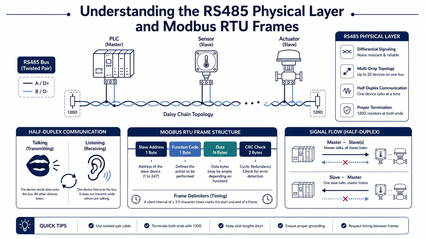
Think of a two-wire RS485 trunk as a shared party line. Every device listens to the same differential pair, but only one transmitter should speak at a time. The master starts a request, the addressed server responds, and the remaining devices stay silent. Unlike a point-to-point connection, a correct response from one device doesn't prove that every branch, connector, or server is healthy.
RS485 carries the bits electrically. Modbus RTU gives those bits meaning. RS485 uses differential signaling, so the receiver evaluates the voltage relationship between the two conductors rather than relying on one conductor against a local ground. That helps reject noise that couples similarly onto both wires, although it doesn't eliminate problems caused by poor routing, excessive common-mode voltage, reflections, bad references, or damaged transceivers.
Build the frame from left to right
A normal Modbus RTU frame contains four practical elements:
- Server address, the node that should process the request.
- Function code, such as a read-coil or read-register operation.
- Data, including the starting address, quantity, write value, or returned register bytes.
- CRC, the error-checking field that lets the receiver reject corrupted data.
The frame isn't marked by a start character. RTU uses silence. A quiet interval of at least 3.5 character times separates frames, and a gap greater than 1.5 character times inside a frame can cause the receiver to treat the message as incomplete. Those timing rules are why a master that starts its next request too early can create failures even when the baud rate and wiring appear correct.
RTU isn't ASCII
Modbus RTU and Modbus ASCII aren't interchangeable settings. RTU frames use binary bytes, CRC checking, and timing-defined boundaries. ASCII represents frame content differently and uses its own delimiters. If a device is configured for ASCII while the master sends RTU, the receiving port may see electrical activity without recognizing a valid request.
A useful diagnostic capture should show the raw request and response, the time between frames, the server address, function code, data length, and CRC result. A bus monitor or oscilloscope can tell you that bits are moving. It can't tell you whether the requested register is the correct process value. Conversely, a valid Modbus exception proves that the server decoded a request, but it doesn't prove that the value mapping is correct.
A clean waveform is only evidence at the electrical layer. A valid CRC is evidence at the frame layer. A believable process value requires a separate register and scaling test.
Wiring the Bus for Reliable Communication
A network can pass commissioning tests and still fail after production starts. A central cabinet full of home-run cables, termination resistors fitted at every device, and shields bonded to any convenient earth point creates a bus that depends on luck. Drives start, contactors switch, and vibration changes a marginal terminal. The master cannot correct a poor physical design.
Treat cable, topology, termination, idle-state bias, routing, and signal reference as one system. Standard-compliant drivers support up to 32 unit loads, with one unit load defined as approximately 12 kΩ input impedance. Actual device loading can be higher because transceivers, isolation circuits, internal bias networks, and termination all affect the electrical budget. Check those values from the installed hardware documentation before adding stations.
Make the trunk linear
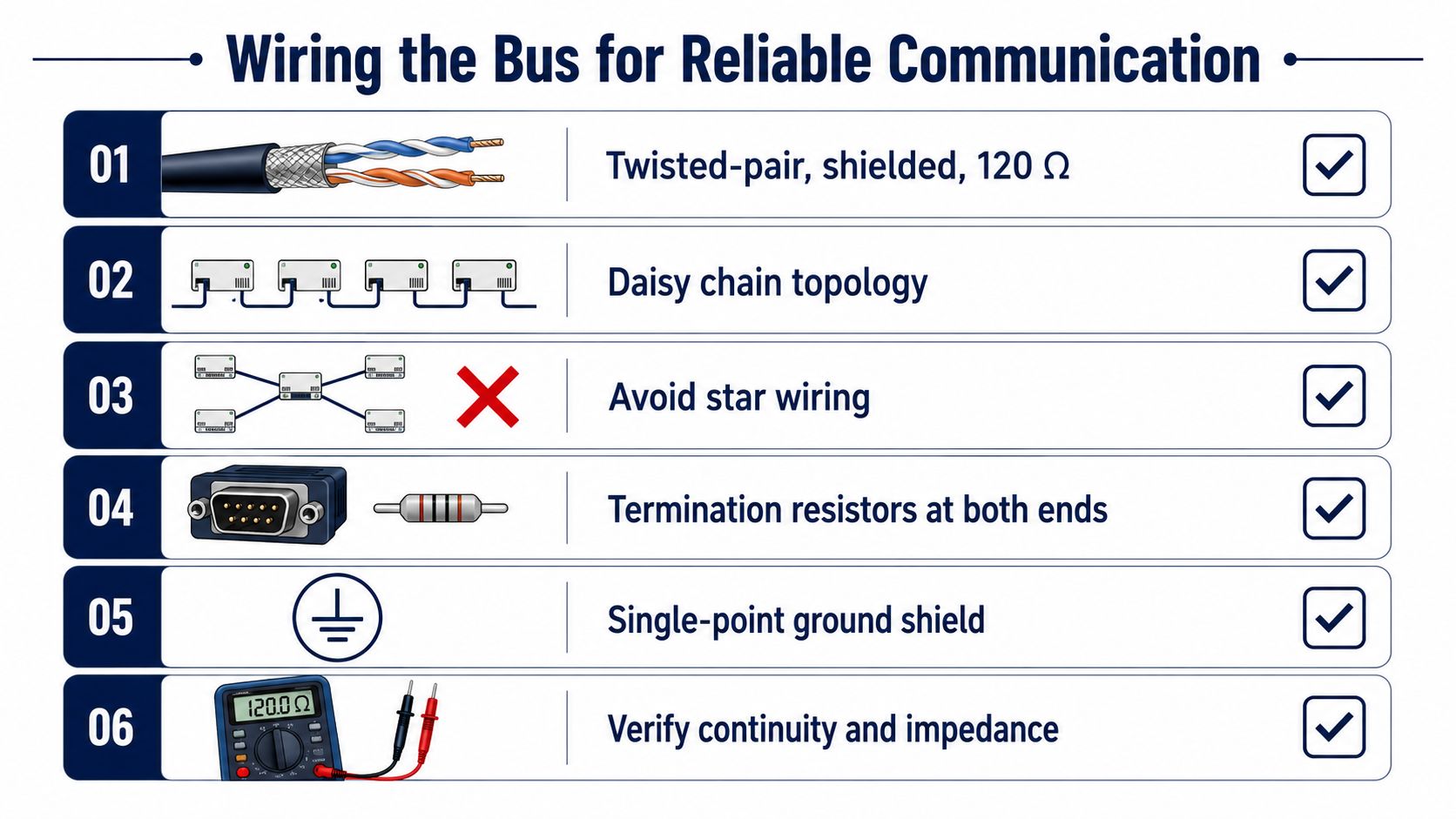
Build a continuous trunk with short drops to each station. A star introduces impedance discontinuities that reflect signal energy into the cable. That arrangement may work during a quiet maintenance shift, then produce CRC errors when a drive switches, a contactor operates, or a loose terminal changes its contact resistance.
Use a shielded twisted pair with approximately 120 Ω characteristic impedance, matching the common RS485 trunk specification in published network characteristics. Keep the pair away from VFD output conductors, motor leads, contactors, and high-current switching paths. Where a crossing is unavoidable, cross the power route perpendicularly instead of running beside it for a long distance. Apply the plant's approved EMC and grounding design. A single separation rule cannot account for every cable tray, enclosure, or switching environment.
Terminate only the electrical ends
Termination belongs at the two physical ends of the bus, not at every station. The common arrangement uses 120 Ω termination at both ends. Many devices include a termination switch, so fitting an external resistor without checking the switch can create a third termination and load the driver excessively.
Biasing serves a different purpose. With no transmitter active, the pair needs a defined idle condition. Some transceivers provide fail-safe behavior. Other designs use a bias network at a selected point. Multiple bias networks can load the bus or oppose one another. Record which station supplies the intentional bias, then disable other networks unless the design calls for them.
Keep signal reference, shield, and earth distinct
A third conductor may provide signal reference, but it does not replace the A/B pair. The shield manages electromagnetic coupling, while protective earth addresses electrical safety. Connect these conductors only at deliberate points defined by the site design. Treating them as interchangeable can create ground-current paths or exceed a device's common-mode limits.
Before energizing the trunk, verify the installation in the field:
- Polarity mapping: A, B, D+, and D- labels vary between manufacturers. Confirm the actual pinout rather than matching labels blindly.
- Continuity: Test each conductor end to end and check for shorts between conductors.
- Termination inventory: Identify every internal and external termination switch, then confirm that only the two electrical ends are enabled.
- Reference design: Confirm isolation, common-mode limits, and the approved reference connection.
- Mechanical integrity: Pull-test accessible terminals and inspect for vibration damage or loose ferrules.
- Cable routing: Check for shared conduits and parallel runs beside motor or VFD output cables.
A commissioning record should capture the trunk route, termination points, bias location, reference connection, and measured faults. That record makes brownfield expansion safer because the next installer can see which electrical choices are intentional rather than adding another resistor or bond by trial and error.
Configuring Addresses Baud Rates and Timing
The parameter layer creates many commissioning delays because the values are often configured in different places. One device may use rotary switches, another a keypad, another a software parameter, and the master may retain an old project file. Treat the serial schedule as a controlled document, not as a collection of defaults.
Every server on one RTU segment needs a unique address. The master must also know whether the device uses RTU mode, which function codes it supports, and how long it may take to respond. Duplicate addresses are especially deceptive. Two servers may drive the pair at once, producing corrupted responses that look like a cable fault.
Match the complete character format
Baud rate alone isn't enough. All nodes must agree on baud, data bits, parity, and stop bits. Common commissioning choices include 9600 and 19,200 bps, with higher rates used only when the installed cable, topology, device support, and noise margin justify them. The published Schneider characteristics use 19,200 bps in their stated bus-length specification, but that doesn't make the same rate suitable for every installation.
Modbus RTU timing is based on character duration. With an 8E1 format, each character contains 11 transmitted bits. At 9600 bps, one character takes approximately 1.146 ms, so the 3.5-character frame boundary is approximately 4.01 ms. These calculations are useful during diagnosis, but the exact device manuals and captured traffic should control the final timeout values.
Estimate the scan before adding tags
A scan-cycle estimate should include request transmission, server processing, response transmission, inter-frame silence, retries, and timeout behavior. A simple successful transaction may appear fast on a bench, yet a plant network can become sluggish when one device responds slowly or when a noisy segment causes repeated retries.
The following table is a planning template, not a universal performance guarantee. The only published bus limit shown here is the Schneider specification for 19,200 bps. Other cells should be completed from the exact cable, device manuals, measured response times, and the process data-age requirement.
| Baud Rate | Max Cable Length | Typical Max Devices | Est. 20-Device Scan Time |
|---|---|---|---|
| 9600 | Site and vendor dependent | Loading and timing dependent | Measure from the final poll list |
| 19,200 | 1000 m under Schneider's published characteristics | 32 stations total under the stated network characteristics | Calculate from captured transactions and retries |
| 38,400 | Site and vendor dependent | Loading, topology, and timing dependent | Measure before committing the SCADA refresh target |
A practical calculation is:
Total scan time = successful transaction time + processing time + inter-request delay + retries + timeout time.
If the SCADA team wants a 500 ms refresh, prove that target against the worst-case poll list rather than assuming it will hold after every drive, meter, and diagnostic block is added. Modbus RTU's request-response design makes the constraint unavoidable. More devices mean more serialized transactions and less usable throughput.
Integrating VFDs and Plant SCADA Systems
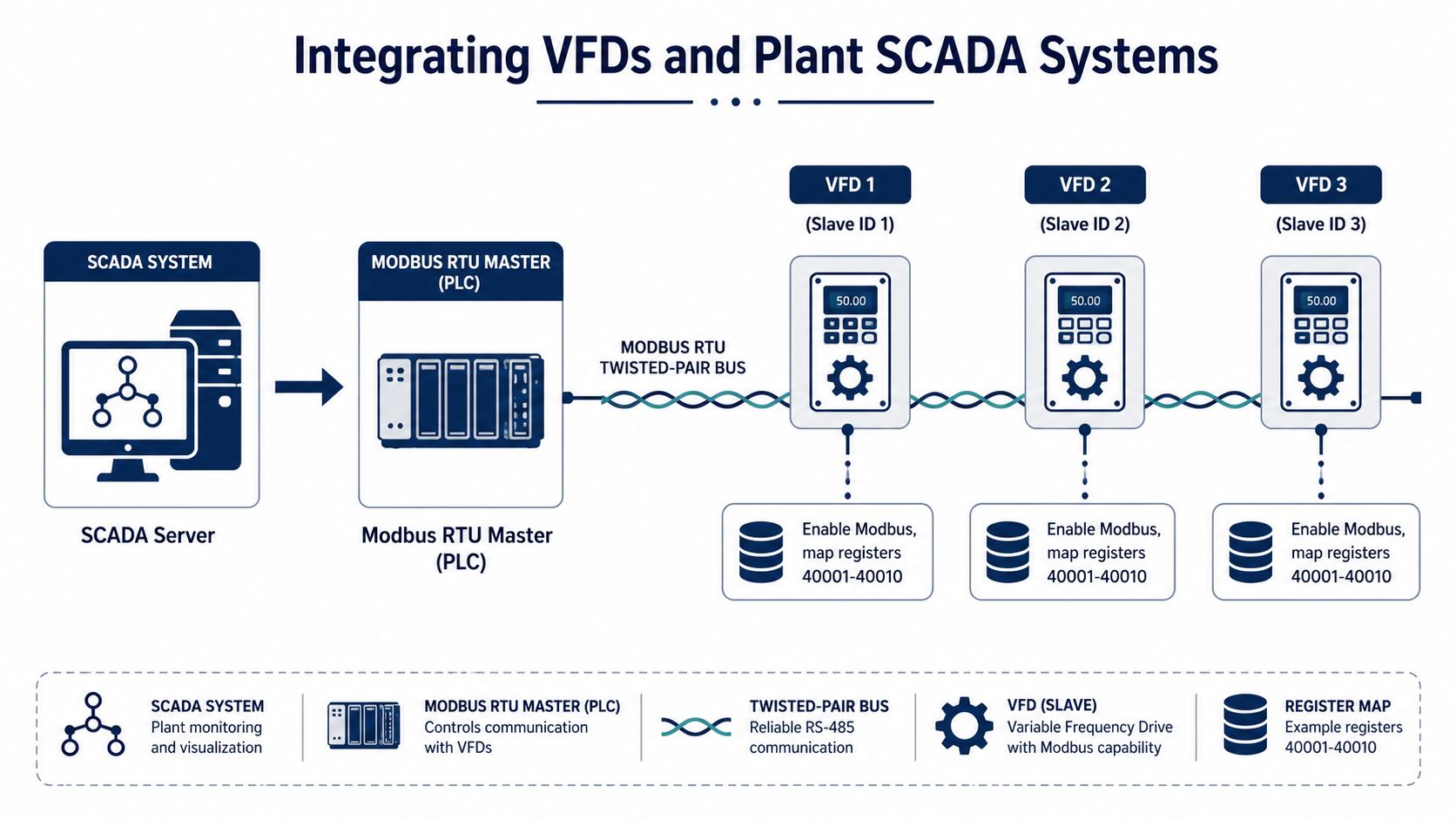
A VFD integration should start with the drive's control philosophy, not with a tag import. Decide which commands belong on the network, which interlocks remain hardwired, what feedback proves that a command took effect, and what the process does when communication quality becomes bad.
On the drive side, enable the built-in serial port or communication option, select RTU mode, assign a unique server address, and match the approved serial settings. Then identify the control word, speed reference, status word, actual frequency, current, fault code, reset command, and any scaling rules. Never assume that a register labelled as a frequency reference accepts engineering units directly. Many drives expect a scaled integer, a percentage representation, or a vendor-specific command-word bit pattern.
Separate command authority from permissive logic
A network command can request run, stop, direction, or speed. It shouldn't replace every physical permissive. Emergency stops, critical trips, guard circuits, and other safety-related functions require the approved safety design. A hardwired run permissive may remain necessary even when the normal start command comes from the PLC.
Use a controlled workflow:
- Create the drive record: model, firmware, option card, address, serial settings, control source, reference source, and fault behavior.
- Build the register map: function code, transmitted offset, width, signedness, scale, units, and access.
- Test one read: capture the raw response and compare it with a known drive state.
- Test status interpretation: change a controlled operating state and verify the status word and feedback.
- Test a bounded command: use an approved low-risk condition, then verify both the protocol response and the drive's actual state.
- Add SCADA tags: publish value, quality, age, raw data where useful, and a clear fault description.
- Group polling: combine contiguous registers only when the device map and data-age requirements allow it.
A register such as 40001 is a documentation reference, not necessarily the address sent in the RTU frame. Some software expects the full reference, while other software expects a zero-based offset. Record both forms in the tag database and test the conversion with a known value.
The S7-200 Modbus communication reference is useful when the controller's transaction setup and the drive's register contract must be aligned. The point isn't to copy a generic address list. It is to preserve the exact relationship between master request, serial response, PLC data type, and SCADA presentation.
Poll for useful data, not every available register
Divide the tag list into control, status, process values, alarms, and diagnostics. Poll fast-changing control and status data more often than configuration or historical information. A single large read can be efficient, but it can also fetch a block containing unused or unsupported addresses. Read only a range the drive explicitly supports.
A healthy integration also handles bad data explicitly. On timeout, CRC failure, invalid byte count, exception response, or conversion error, mark the tag quality bad or stale and retain the last value only as historical context. Don't let the SCADA screen display an old speed as if it were current.
The following video can help technicians visualize the relationship between the controller, serial transaction, and device data path.
<iframe width="100%" style="aspect-ratio: 16 / 9;" src="https://www.youtube.com/embed/WeyAjvMLLzk" frameborder="0" allow="autoplay; encrypted-media" allowfullscreen></iframe>Security and Scalability Limits You Cannot Ignore
A serial bus isn't automatically secure because it isn't connected directly to the corporate network. In a brownfield plant, RS485 conductors may run through accessible cabinets, junction boxes, machine panels, or maintenance areas. Anyone who gains physical access to the pair may be able to place a device on the line, inject a valid-looking request, issue a broadcast, or interfere with normal polling.
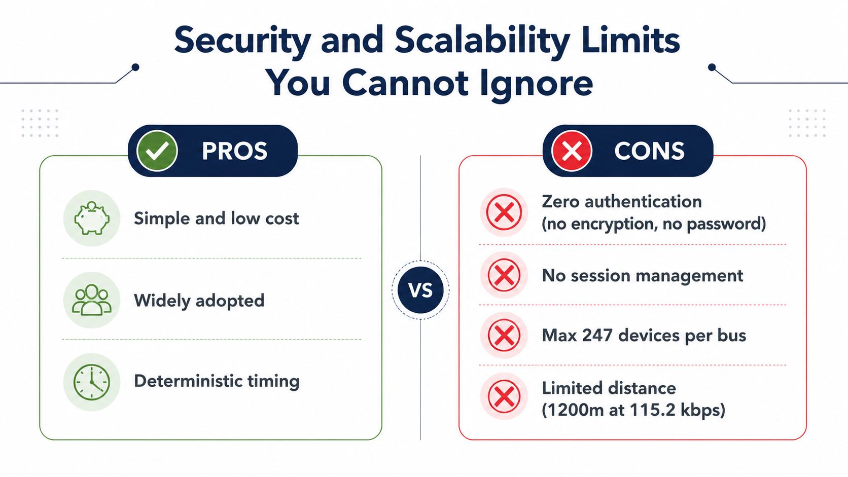
Traditional Modbus RTU provides no authentication, encryption, or message integrity protection. A 2025 IETF draft states that formal standards addressing security for Modbus over RS485 are absent, while vulnerability notices and guidance continue to identify Modbus RTU-related exposure during 2025 and 2026. See the IETF draft on Modbus serial-link security.
Treat physical access as protocol access
The first controls are physical and procedural:
- Lock cabinets: Restrict access to serial terminals, gateways, USB service ports, and drive option cards.
- Control maintenance connections: Record who connects portable commissioning equipment and remove temporary adapters afterward.
- Segment gateways: Place serial-to-Ethernet gateways behind approved firewalls and OT segmentation.
- Restrict write paths: Separate read-only monitoring from command-capable clients wherever the equipment supports it.
- Monitor addresses: Investigate unexpected server addresses, unexplained broadcasts, duplicate responses, and sudden changes in request frequency.
- Preserve configuration evidence: Keep approved address schedules, serial parameters, gateway settings, and drive backups available for comparison.
A firewall can't authenticate a Modbus RTU frame that reaches an exposed serial pair. It can reduce the upstream attack path, but it doesn't replace cabinet control, network segmentation, or command authorization.
Know when the bus has become the wrong architecture
Schneider's published characteristics specify 32 stations total, typically 31 servers and one master. That is a network design limit, not a promise that a fully populated bus will meet every process refresh target. The technical constraint appears earlier when the master must poll more devices, wait for slow responses, retry failed requests, and keep data within its required age. Technical analysis also notes that payload throughput at 9600 baud is only a few kilobytes per second, with real-world latency affected by retries, device response time, and bus contention. The Modbus RTU performance discussion describes why a shared request-response bus degrades as the poll list expands.
Use a gateway or a different field architecture when the application needs more aggregate throughput, independent polling domains, stronger security controls, or clearer fault containment. A gateway can organize serial segments, but it won't repair poor wiring or make unauthenticated RTU messages trustworthy. If the process requires fast coordinated control, design that requirement explicitly rather than stretching supervisory Modbus RTU beyond its practical role.
Security decision: If a person can reach the pair and connect a device, assume the protocol can be manipulated unless the surrounding physical and architectural controls prevent it.
Diagnosing Common Field Failures and Communication Drops
Start at the last proven boundary. Don't reboot every controller before you know whether the master transmitted, the server decoded, or the register map is wrong.
| Symptom | Tool or evidence | Corrective action |
|---|---|---|
| Silent server | Bus monitor, serial adapter, address schedule, voltage checks | Verify power, address, polarity, RTU mode, baud, parity, stop bits, and termination. Isolate one server if the segment is crowded. |
| CRC mismatch | Raw request and response capture, oscilloscope | Check reflections, star branches, duplicate transmitters, noise, loose terminals, bias, and termination placement. |
| Framing errors | UART diagnostics and measured bit timing | Match baud and character format across every node. Check whether one device was reset to a default configuration. |
| Bus contention | Capture showing overlapping responses or simultaneous transmitters | Ensure only one master owns the port and that no gateway or service adapter is polling independently. |
| Intermittent drops | Terminal inspection, continuity testing, shield and reference review | Tighten vibration-affected connections, repair damaged cable, and correct unintended shield-ground paths or reference problems. |
A multimeter can confirm continuity and obvious shorts, but it can't decode RTU frames. Use a USB-RS485 adapter with a bus monitor for transaction evidence, and use an oscilloscope when you need to see edge distortion, noise, or timing. Compare one known-good request with one failing request rather than changing several parameters at once.
For drive-specific symptoms such as trips, incorrect commands, or a mismatch between keypad and SCADA behavior, use a controlled VFD troubleshooting workflow. Keep the drive in a safe state while testing writes, and document every temporary change before restoring the approved configuration.
DUCHENG Industrial provides multi-brand VFD commissioning, structured on-site troubleshooting, repair, preventive care, and RS485 or Modbus integration support for industrial facilities. If a drive network is timing out, producing recurring communication faults, or needs a controlled restart and register-mapping review, visit DUCHENG Industrial to discuss the required service.