
A practical guide to servo drive repair: safe shutdown, fault isolation, bench tests, return to service and when to send the drive to a workshop.
The line has stopped, the axis won't enable, and the drive display points to a fault nobody wants to see during production. There's a spare amplifier on the shelf, but installing it without checking the motor, feedback cable and braking circuit could leave you with the same trip, or another damaged drive.
Servo drive repair starts with proving where the fault lives. The useful question isn't whether the amplifier is faulty. It's what failed, what caused it, and which measurements will prove the machine can run safely again.
Table of Contents
- Safe Shutdown and Intake Before You Touch the Drive
- Matching Symptoms to Fault Categories
- Isolating Feedback, Motor and Cable Faults
- Repairing the Amplifier at Component Level
- Bench Test Thresholds and Staged Power-Up
- Returning a Repaired Drive to Service Safely
- Deciding Between In-Place Repair, Workshop Repair and Replacement
Safe Shutdown and Intake Before You Touch the Drive
A servo drive can retain lethal DC-bus voltage after its incoming supply is disconnected. Only electrically qualified personnel should perform this work, using the machine's electrical drawings, manufacturer procedures and site electrical-safety controls.
Secure the equipment and preserve the evidence
-
Capture the fault information before shutdown, if it's safe. Record the alarm exactly as displayed, save the available alarm history and export the parameter set. Don't keep cycling power to see whether the fault disappears. That can erase useful evidence or stress damaged components.
-
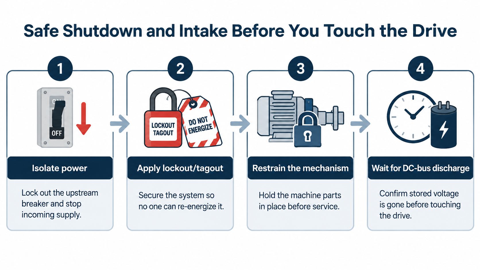
Isolate every relevant supply and apply lockout/tagout. Identify the upstream disconnect, separate control supplies and any shared DC-bus connection. An extinguished display doesn't prove that all hazardous energy sources are isolated.
-
Restrain gravity-loaded mechanisms. Support vertical axes with an engineered mechanical restraint before disconnecting motor or brake wiring. Don't rely on motor holding torque, and don't assume a holding brake is an adequate maintenance restraint.
-
Wait for discharge, then verify absence of voltage. Follow the manufacturer's discharge procedure and measure at the designated terminals with a suitably rated meter. Prove the tester before and after use. The charge indicator is useful information, not permission to touch the bus.
Use this shutdown sequence as a reminder alongside the machine-specific procedure.
Build an intake record someone else can use
Photograph the nameplate, terminal assignments, connector positions and visible damage before disturbing anything. Include cabinet filters, cooling passages and contamination, not just the burnt component.
Record when the fault happens: at enable, during acceleration, while holding position, during deceleration or after sustained operation. A machine that trips when cold but runs after warming needs a different investigation from one that trips only under heavy load. Record ambient conditions and the actual operating sequence rather than writing “intermittent.”
Our service-request intake calls for:
- Equipment identity: Drive brand, exact model code, rated power and voltage.
- Fault evidence: Exact displayed code, alarm history and photographs.
- Operating conditions: Fault timing, load, cabinet condition and environment.
- Configuration: Available parameter backup, motor identification and relevant wiring drawings.
A complete paper record should let another technician identify the unit, reproduce the reported condition and understand what has already been tested. Keep observations separate from conclusions: “fan stationary while commanded on” is evidence; “drive overheated because the board failed” is still a hypothesis.
Matching Symptoms to Fault Categories
| Symptom | Likely fault category | First check |
|---|---|---|
| Overcurrent or ground-fault alarm at power-up | Power stage or motor insulation | Disconnect motor cable and insulation-test the motor |
| Encoder or feedback alarm, motor jitters | Feedback device or cable | Encoder supply voltage at connector and A/B signals on a scope |
| Overvoltage alarm during deceleration | DC bus or braking circuit | Braking resistor, brake transistor and DC bus voltage |
| Overtemperature trip after warm-up | Cooling or thermal load | Fan operation, heatsink dust and actual mechanical load |
| Drive will not enable, no alarm | Control power or enable circuit | Control supply voltage and STO and enable wiring |
| Position drift or following error | Mechanical coupling or feedback scaling | Coupling slip, encoder scaling and homing |
| Rough running at no load | Motor winding, bearing or feedback | Phase resistance balance and bearing noise |
| Intermittent fault after warm-up | Loose busbar, connector or aging capacitor | Torque check of connections and capacitor condition |
Read this table as a test order, not a diagnosis. Start with the observed symptom, select the most plausible category, then perform the check that separates it from neighbouring causes. Carry out disconnected tests under isolation and live measurements only under an approved energized-test procedure.
Use the operating sequence to narrow the fault
Suppose the drive trips on overvoltage only during deceleration. The motor is returning energy to the DC bus, so investigate the regeneration path: resistor continuity, connections, braking configuration and brake-switch operation. Condemning the bus capacitors first skips the circuit responsible for dissipating that energy.
For another hypothetical example, an axis runs normally but trips on temperature after about forty minutes at load. Check fan operation, blocked heatsink passages, cabinet airflow and mechanical demand before ordering a power module. The elapsed time suggests heat accumulation, but it doesn't identify which component is responsible.
Feedback alarms need similar discipline. A damaged connector can interrupt position signals without any failure in the amplifier's power stage. A slipping coupling can produce a following error even when the encoder reports the motor shaft correctly.
Practical rule: Write down what supports your diagnosis and what measurement would disprove it.
When competing explanations fit equally well, start with the cheaper, reversible test. Inspect or substitute a compatible feedback cable before opening the amplifier. Check the coupling before changing loop tuning.
The same separation of supply, load and drive faults underpins our VFD troubleshooting guide, although servo feedback and positioning require additional checks.
Isolating Feedback, Motor and Cable Faults
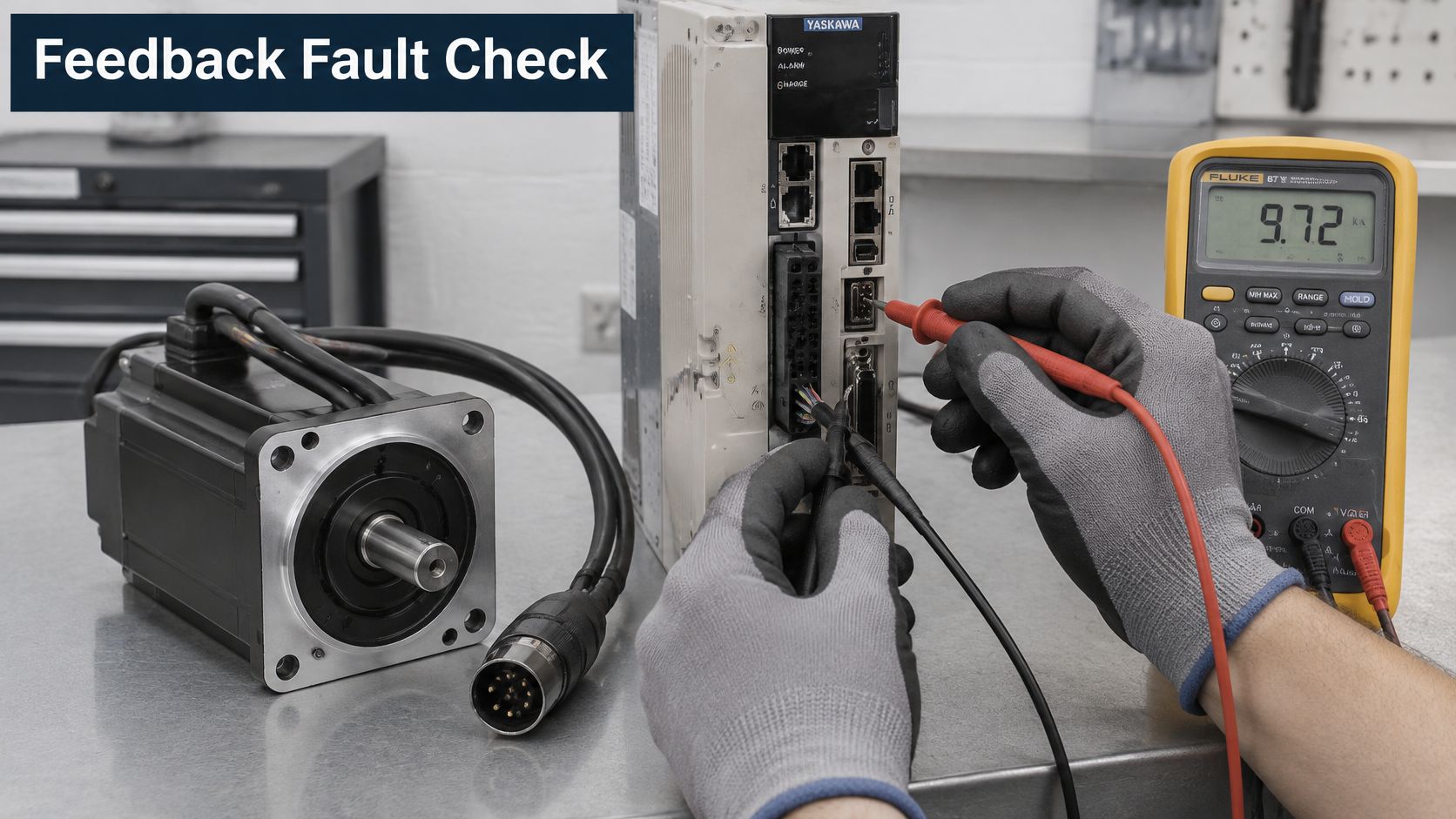
A servo axis that reports a feedback fault has four plausible sources: encoder, cable, motor winding and amplifier input. Isolation is how you decide which one to repair, rather than swapping the drive and hoping the alarm moves with it. Keep power-circuit work isolated. Encoder supply and waveform measurements may need controlled energization, so treat those as a separate test state with the mechanism secured, motion prevented and a clear stop condition agreed at the controls. Identify accessible test points and label them before the first probe goes in.
Separate the signal path from the power path
-
Check encoder supply at the connector. Under the approved powered-test arrangement, measure supply and return at the encoder as well as at the drive. Compare the readings with the encoder datasheet. Correct voltage at the amplifier and low voltage at the motor point to cable resistance, connector trouble or an overloaded supply.
-
Isolate again and test the cable. Disconnect both ends before continuity testing. Check every conductor, unintended conductor-to-conductor paths and shield termination. Flex suspect cable sections and connectors while watching continuity, because an intermittent break often appears only under movement.
-
Inspect feedback waveforms. For incremental feedback, use an oscilloscope at the receiving interface and check A/B channel edges, phase relationship and amplitude consistency. Use differential or isolated measurement equipment where required. A grounded scope connection on a floating feedback circuit can create a short. Serial and absolute feedback need the protocol-specific diagnostic method, not a generic scope trace.
-
Test motor insulation independently of the amplifier. Use the motor manufacturer's stated DC test voltage and minimum resistance for the motor being tested. Those values are model-specific and do not transfer to every motor, encoder or sensor. Disconnect the amplifier and sensitive accessories, follow the actual motor's procedure, and discharge the tested winding afterward.
-
Measure winding resistance. Use a milliohm meter with lead compensation and compare phase-to-phase readings at consistent temperature. An imbalance outside the motor manufacturer's tolerance calls for motor investigation before re-energization.
Prove the suspect component with a controlled swap
Substitute only compatible, verified hardware, and change one item at a time. If the fault follows the suspect cable when that cable is used with a known-good compatible motor, the cable becomes the leading cause. A successful swap confirms the suspect part under the tested conditions. Intermittent faults that did not recur during the test remain unresolved, so record the test duration and the operating state used.
Use the demonstration alongside the relevant equipment documentation.
<iframe width="100%" style="aspect-ratio: 16 / 9;" src="https://www.youtube.com/embed/fbW2QMPdcl4" frameborder="0" allow="autoplay; encrypted-media" allowfullscreen></iframe>Do not replace an encoder on suspicion alone. Preserve the required rotor-angle offset and perform the specified absolute-position referencing procedure. Keep vertical mechanisms restrained throughout.
DUCHENG's motor assessment covers windings, insulation, bearings, feedback devices, cleaning, mechanical maintenance, and electrical and mechanical function testing. Finish with a written status for each item: motor insulation accepted, winding balance accepted, cable proven or suspect, feedback verified or unresolved. Anything untested stays open.
Repairing the Amplifier at Component Level
Treat the amplifier as interconnected power and control circuits, not a box containing an alarm code. Start with the damage pattern and the operating conditions recorded at intake. That combination tells you where to look first and which tests are worth the bench time. A replacement board will not correct an external cause that remains in the cabinet.
Inspect contamination, cooling, connections and electrical conditions before any controlled functional test. That order matters. Conductive dust or a blocked heatsink can create the fault you are about to chase through the power stage. A clean cabinet with stable cooling removes one whole class of intermittent behavior before you probe a single component.
Follow the physical evidence
With isolation verified, inspect for conductive dust, oil film, salt deposits, damaged insulation, loose busbar joints and heat discoloration. Look behind fans and along heatsink passages. Photograph deposits and damage before cleaning removes evidence. Carbon tracking, cracked solder around heat-generating parts and corroded terminals narrow the fault path before you apply power. Do not power a board with visible carbon tracking to see whether it still runs.
Inspect DC-bus capacitors for leakage, swelling and damaged connections, but do not accept appearance as a condition test. Capacitance, equivalent series resistance and leakage need suitable instruments and component-specific acceptance criteria. A capacitor can look normal and still perform poorly.
Check the braking resistor and its wiring, then inspect semiconductor paths for shorts using the appropriate disconnected test method. Gate-driver static checks can identify damaged components, but actual switching waveforms require a controlled powered setup with appropriate probes. You cannot verify dynamic gate-drive performance on an unpowered board.
Verify incoming phase balance and control supply through a separately planned live-test procedure before enabling the repaired unit.
Match the repair to the available capability
- Plant-team work: trained personnel may replace approved fans, clean cooling passages and retorque connections to documented values. Capacitor replacement belongs here only when the team has the authorization, discharge controls, soldering capability and exact component specification.
- Workshop work: power-module replacement, gate-driver repair, damaged multilayer boards and uncertain fault propagation need bench diagnostics and controlled testing.
Remove loose dust with an antistatic brush and controlled extraction. Use clean, dry, low-pressure air only where permitted, without overspeeding fans or driving debris into components. Do not wash the amplifier with water. Board cleaning and restoration of any protective coating require compatible materials and controlled preparation.
A repaired board can pass electrically while the cabinet still contains the reason it failed.
A failed fan can increase thermal cycling and contribute to solder-joint damage. A loose busbar joint can heat locally and damage the surrounding connection. Replacing the visibly failed component without correcting either condition leaves a credible repeat-failure path.
The repair decision is a proof exercise: establish the damage path, verify the failed part, and correct the initiating cause. If that chain is incomplete, a board swap is a bet, not a repair. DUCHENG's workshop process includes controlled disassembly, cleaning, component-level repair, available parameter or program restoration, reassembly and functional testing. The gate to powered testing is explicit: isolation checks pass, replacement components are verified, and the identified initiating cause has been addressed.
Bench Test Thresholds and Staged Power-Up
| Test | Method | Pass reference |
|---|---|---|
| Insulation resistance | Manufacturer-approved insulation test, motor disconnected from amplifier | Meets the motor's specified minimum |
| Phase-to-phase winding resistance | Measure U-V, V-W and W-U with a milliohm meter | Balanced within motor manufacturer tolerance |
| Encoder supply voltage | Multimeter at encoder connector while powered | Within encoder datasheet range |
| Incremental A/B signal | Oscilloscope at drive input | Clean, correctly phased pulses with consistent amplitude |
| No-load rotation | Controlled enable at slow speed command | Smooth rotation with no feedback alarm |
| Thermal rise at rated load | Log heatsink and motor temperatures over the run | Within equipment limits, stable, with no repeat trip |
| Alarm-free endurance | Staged loaded run with increasing load | No alarms over the agreed duration; define acceptance before testing if unset |
Manufacturer limits govern acceptance. A reference from another servo family isn't a substitute for the installed motor and amplifier documentation. Insulation failure stops energization; unacceptable winding imbalance sends the investigation back to the motor.
Increase energy and load deliberately
-
Apply controlled power without motion. Use an approved bench arrangement with suitable protection, precharge and current limiting. Don't improvise a generic DC supply connection to a drive's bus. Monitor supply behaviour and bus charging; unexpected current, unstable rails or abnormal heating stops the test.
-
Verify feedback before commanding rotation. With the axis safely uncoupled and torque disabled, turn the shaft by hand only where the motor arrangement permits. Confirm position changes consistently and that the feedback direction is correct. Missing counts or feedback alarms prevent enable.
-
Command slow no-load rotation. Secure the motor and guard exposed shafts and keys. Check direction, smoothness, current and noise. Stop for oscillation, unexpected acceleration, excessive current or abnormal mechanical sound.
-
Review the alarm history. Preserve the original record before clearing stored faults. Repeat the intended enable and stop sequence, then confirm no new unexplained alarms appear. Don't dismiss an alarm because resetting it allows another run.
-
Apply load progressively. Increase demand through agreed operating stages while recording current, temperature and vibration. Stop if readings exceed equipment limits, temperature continues climbing without acceptable stabilization, or the original symptom returns.
Make the test record useful
Log ambient temperature as well as equipment temperature. A cool open bench doesn't reproduce a loaded cabinet with restricted airflow, so thermal acceptance must account for the intended installation.
Acceptance matters more than a clean display: Record the load, duration and conditions under which the drive stayed alarm-free.
The repair record should contain instrument identification, measured values, acceptance limits, configuration, test motor, load profile and unresolved limitations. Record thermal rise at rated load where the bench can reproduce it safely. If full application load wasn't available, state that plainly rather than presenting a no-load pass as complete validation.
Returning a Repaired Drive to Service Safely
A bench pass confirms performance under bench conditions. It doesn't authorize unrestricted motion on the production machine.
Use a signed commissioning gate
- Compare parameters: Check the restored configuration against the approved backup and record every difference. Pay particular attention to current limits, direction, brake timing and motion settings.
- Verify versions: Confirm firmware and option-card compatibility with the validated machine configuration. Don't install an available update merely because it's newer.
- Validate the axis: Check encoder scaling, homing, travel limits and position accuracy under restricted, supervised motion.
- Test safety functions: Validate safe torque off and other applicable functions through their intended wiring and approved test procedure. Never bridge a safety input to make the machine run.
- Check communications: Confirm fieldbus identity, addressing and expected controller connections before restoring normal network access.
- Approve the change record: Attach configuration differences, electrical test results, safety validation and restart authorization to the maintenance record.
Include network behaviour in acceptance
The industrial cybersecurity annual review discusses investigation of CANopen communications and limitations in detecting attacks across layered fieldbus systems. Electrical functionality alone doesn't establish that a connected drive's communications are trustworthy.
If monitoring connectivity is added during repair, define who can access it and which data may leave the production network. Use segmentation and controlled access rather than connecting diagnostic equipment directly to unrestricted plant infrastructure.
Schedule a supervised production run through the operating conditions associated with the original fault. Watch cabinet temperature, current, position performance and communications, not just the drive display.
Track first-pass restoration, repeat failures and alarm-free operating time using clearly defined plant measures. Keep recurrence records tied to the original repair so a returning symptom triggers renewed diagnosis rather than another reset.
Deciding Between In-Place Repair, Workshop Repair and Replacement
- Repair in place when the fault is isolated to accessible wiring, cooling or approved service parts, and the site can complete the required acceptance tests.
- Use workshop repair when controlled disassembly, board-level diagnosis, power-stage work or specialized feedback testing is necessary.
- Replace or exchange when suitable parts are unavailable, damage is uneconomic to recover, compatibility can't be established, or safe operation can't be validated.
Compare complete recovery routes
A failed drive isn't automatically at end of life. An amplifier with serviceable power electronics but worn cooling components may justify refurbishment. Extensive power-stage damage combined with unavailable parts can favour a verified exchange unit.
Parts and documentation access are legitimate decision constraints. The U.S. product-repair study examines those barriers across evaluated products, although it isn't a servo-drive repairability assessment.
Assess capacitor condition, semiconductor damage, firmware and encoder compatibility, safety requirements and production criticality. Don't claim precise remaining semiconductor life from a visual inspection. Compare measured condition and known operating stress against the consequences of another outage.
Replacement cost includes more than procurement: parameter recreation, engineering labour, motion tuning, machine revalidation and restart risk all belong in the decision. A tested compatible exchange may shorten recovery, but an unverified used unit merely introduces another unknown. Our on-site versus workshop decision guide helps distinguish work suited to field conditions from work requiring controlled facilities.
Our Deep Repair coverage includes servo drives and servo motors alongside variable frequency drives and human-machine interfaces. Workshop deliverables include intake and diagnosis records, repair notes and replaced components, test records, relevant parameter documentation and recommended next maintenance.
Prepare the nameplate details, exact fault code, operating conditions, photographs and available backups before submitting the unit. That package lets the engineer assess the fault rather than begin by reconstructing its history.
DUCHENG Industrial provides structured diagnosis and workshop repair for servo drives and servo motors, including component-level work and functional testing. Visit DUCHENG Industrial to submit your model code, fault description and nameplate photographs for engineering review, and identify whether field correction, workshop repair or replacement is the appropriate next step.