
See what a variable frequency drive unit contains, how LV, MV and HV ratings differ, and which commissioning checks protect the motor.
A 2024 IEEE paper estimated that worldwide adoption of high-efficiency motor-driven systems, including variable-speed drives, could achieve energy savings of up to 1,000 TWh per year, as published in the IEEE Industrial and Commercial Power Systems Technical Conference proceedings. That figure is about fleets of motors, not about the one cabinet on your mezzanine.
The box in front of the motor is a variable frequency drive unit, and the nameplate is not the whole system. Line voltage, cable length, frame bonding, and the motor's insulation determine whether a new unit operates smoothly or damages bearings. In many plants across China and Southeast Asia a 6 kV or 10 kV lineup is called high voltage. Under IEC that same cabinet is still medium voltage. Order to the line voltage, not the local nickname.
Table of Contents
- What a Variable Frequency Drive Unit Is
- Voltage Classes from LV through HV
- Power Path Inside the Cabinet
- Auxiliaries That Belong with the Unit
- Commissioning Checks Before Handover
- Plant Cases That Change the Result
- Repair, Recondition or Replace Decision
What a Variable Frequency Drive Unit Is
A variable frequency drive unit is the packaged assembly that takes fixed-frequency AC, turns it into DC, and rebuilds AC at the frequency and voltage you command so shaft speed follows the process.
Say a cooling-water pump has spent ten years across the line. Flow is set with a discharge valve. The motor still runs near synchronous speed, and the valve throws the unused head away as pressure drop and heat in the water. Fit a drive, command 40 Hz instead of 50 Hz, and the pump moves only the flow the exchanger needs. The valve can stay mostly open.
A soft starter only limits inrush, then hands the motor back to line frequency. A contactor starter doesn't control speed at all. The semiconductors are the gearbox: they change the electrical ratio. The shaft, coupling, and foundation still have to match the motor and the load. A wrong ratio on a sound mechanical train, or a right ratio on a bad ground, both fail in the field.
By the end of this walk-through you should be able to read the voltage class off the nameplate, name the power path inside the cabinet, list the auxiliaries that belong on the single-line, and know which checks protect the motor before handover.
Swapping the box often fails to fix a repeat trip when the cable, the grounding, or the motor insulation was the real cause.
Voltage Classes from LV through HV
| Class | What sites often call it | Typical power | Usual loads |
|---|---|---|---|
| Low voltage | LV inverter or low-voltage VFD | Fractional kW to about 1–2 MW | Pumps, fans, conveyors, packaging |
| Medium voltage | High-voltage VFD in many Chinese and Southeast Asian plants; medium voltage under IEC | A few hundred kW to tens of MW | Large fans, mills, compressors, process pumps |
| High voltage | Rarely a packaged VFD; supply is stepped down | Multi-10 MW utility-scale machines | Very large utility or pipeline drives via a transformer |
Match the line voltage to a row, then use the site nickname only as a cross-check.
Low voltage in the IEC band
Low voltage in drive practice is the IEC band at or below 1 kV. Common industrial nameplates sit at 200–240 V, 380–415 V, 480 V, and 690 V. Power runs from fractional kilowatts to roughly 1–2 MW, using a single bridge or paralleled modules. You will see these on pumps, fans, conveyors, and packaging lines, usually wall-mount or floor-standing, cooled by a fan or an air duct.
If the motor nameplate says 400 V and the board says 380 V, that is still this row. Don't "upgrade" the spare to a 690 V frame because the store label looked bigger.
Medium voltage, and the name people argue about
Medium voltage under IEC runs from above 1 kV to 35 kV. Packaged drives commonly sit at 2.3, 3.3, 4.16, 6, 6.6, 10, 11, or 13.8 kV, from a few hundred kilowatts into the tens of megawatts. Many of these units include an integral phase-shifting transformer and live in a walk-in or container enclosure.
Here is the naming trap. In China and much of Southeast Asia, a 6 kV or 10 kV cabinet is called a high-voltage VFD. IEC still calls that medium voltage. A spare parts note that says "HV drive" can mean a 6 kV cell inverter on one site and something above 35 kV on another. Filters, cable, and a service visit all follow the actual line, not the painted words on the door.
What true high voltage looks like
True high voltage, above 35 kV, is rarely a single packaged inverter. The motor is fed through a step-down transformer, and the drive itself sits on the lower side of that transformer. If someone asks you to quote a "110 kV variable frequency drive unit" as one cabinet, stop and draw the transformer.
The same six-pulse topology can be acceptable on a stiff utility bus and unacceptable on a weak transformer or a generator. Voltage class doesn't settle power quality. It only tells you which row the asset belongs in.
When you order spares, output filters, or a service visit, write the line voltage and the rated current from the nameplate first. A short guide to reading a drive nameplate keeps the team from copying the site nickname into the purchase order.
Power Path Inside the Cabinet
Stand at the single-line and point along the path. Everything later, filters, tests, and heat, hangs on these blocks.
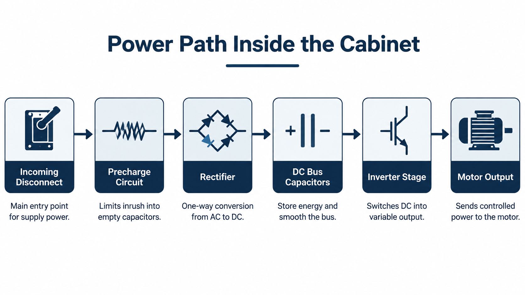
From the disconnect to the reservoir
The incoming disconnect is the entry. Just after it, the precharge circuit limits inrush into empty capacitors. Close the main without precharge and the caps look like a short for the first half-cycle.
The rectifier is the one-way door. On many low-voltage units it is a six-pulse diode bridge. On larger medium-voltage units it is often a 12-, 18-, or 24-pulse bridge behind a phase-shift transformer. An active front end replaces the diodes with controlled switches when the process must regenerate, or when you need input current close to sinusoidal.
The DC link is the reservoir. Low-voltage units use electrolytic or film capacitors. Medium-voltage units often use a different capacitor and bus arrangement. A brake chopper may sit across that bus for occasional stops. If the reservoir voltage sags under load, the inverter has nothing clean to switch.
The valve, the rack, and the heat
The inverter is the valve. Most low-voltage units use IGBTs. Medium-voltage designs use IGCT, IEGT, MV-IGBT, or series-connected cells in a cascaded H-bridge. Output voltage is a PWM pattern. The fundamental frequency of that pattern is the speed command. Voltage rises with frequency so the motor flux stays in a sensible range, until you hit field weakening.
Behind the power stage sits the control rack: processor, gate-driver boards, current sensors, a keypad or remote HMI, and either an encoder or a sensorless estimator. Firmware and hardware share the protections you will see on the fault list.
- DC overvoltage: the reservoir is above what the caps and devices can hold, often on a fast decel.
- Overcurrent: the valve or the motor is asking for more than the bridge will give.
- Ground fault: current is leaving the intended path, often into a cable or a winding.
- Motor thermal model and semiconductor thermal limits: the unit trips on calculated heat, not only on a measured overload relay.
Heat leaves through the bridge devices and the DC capacitors. A failed cabinet fan is an electrical fault waiting to happen, because those same parts are where the energy that doesn't reach the shaft ends up.
Before you leave the cabinet, sketch five blocks in order: disconnect and precharge, rectifier, DC link, inverter, motor. Auxiliaries and handover checks attach to that sketch, not to the brand on the door.
Auxiliaries That Belong with the Unit
Treat the nameplate box as incomplete until the single-line shows its neighbours. A drive that looks fine on the bench can still be the wrong system once cable, ground, and bus are attached.
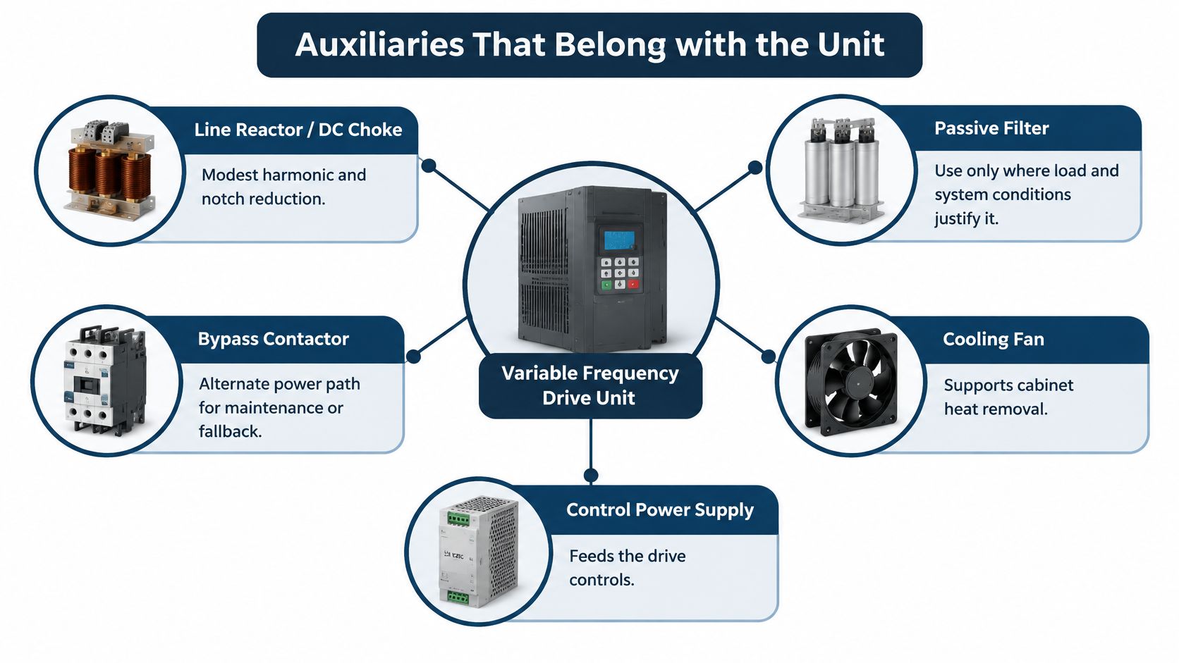
Line side
On the supply, a line reactor or DC choke gives modest harmonic and notch reduction. A passive filter belongs only where load and resonance are known. An active harmonic filter earns its place when many drives share a weak bus. A multipulse medium-voltage unit doesn't exist, electrically, without its phase-shifting transformer. That transformer is not an optional extra. It is the topology.
Motor side and the kilowatt breakpoints
On the motor side, a dv/dt filter is the usual answer once low-voltage cables pass roughly 50–100 m, and on any long medium-voltage feeder. A sine filter is the next step when the motor insulation is old or the cable is very long. A common-mode choke is about shaft voltage, not about making the voltage waveform pretty.
Harmonic distortion increases motor heating and can compromise bearing lubrication, and fast switching can put shaft voltage on the race. Guidance cited by ABB, discussed in a Siemens white paper on drive harmonics, recommends an insulated non-drive-end bearing at or above 100 kW, and both an insulated bearing and a common-mode filter at or above 350 kW. Use those breakpoints as a starting spec, not as a substitute for a shaft-voltage measurement.
IEC 61800-3 does not prescribe current-harmonic limits for industrial non-public networks. It points you at the total installation. The auxiliary is chosen for that installation, not because a catalog page lists it as standard.
Braking and the room around the cabinet
A braking resistor and chopper suit occasional stops. An active front end or regen module suits a load that overhauls often, such as a downhill conveyor or a winder. Around the cabinet you still need forced air, an air-to-air or liquid heat exchanger, and space heaters if the room sweats during shutdown. Motor cable should be shielded, with the shield landed the way the design requires, not the way last year's job happened to land it. Upstream protection has to respect semiconductor let-through, not only cable ampacity.
| Auxiliary | Trigger | Breakpoint or rule |
|---|---|---|
| Line reactor or DC choke | Modest harmonic and notch reduction | Conditional on the shared-bus study |
| Phase-shifting transformer | Multipulse medium-voltage unit | Required for the topology |
| Active harmonic filter | Many drives on a weak bus | Conditional on measured distortion |
| dv/dt filter | Long motor cable | Often past roughly 50–100 m on LV, any long MV feeder |
| Sine filter | Old motor insulation or very long cable | Conditional on insulation test |
| Insulated non-drive-end bearing | Shaft voltage risk | At or above 100 kW as a starting spec |
| Common-mode choke | Shaft voltage or bearing current | At or above 350 kW alongside an insulated bearing |
| Braking resistor and chopper | Occasional stops | Conditional on duty cycle |
| Active front end or regen | Frequent overhauling load | Conditional on duty cycle |
Mark each item on your drawing as required, conditional, or absent. A blank box next to "output filter" is how the next outage gets misdiagnosed as a bad inverter.
Commissioning Checks Before Handover
This is a handover overview for maintenance and E&I. It isn't a substitute for the OEM manual or a live-work permit. A fuller field list sits in this VFD commissioning checklist.
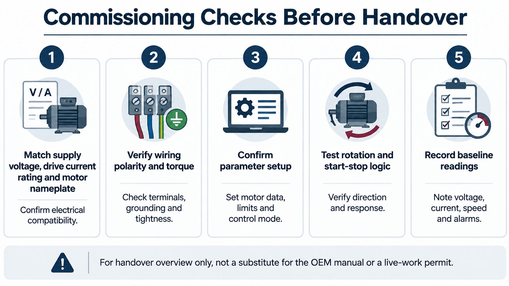
The seven checks, in order
- Match supply voltage, drive current rating, and motor nameplate to the parameter set, including base frequency and cooling type. A TEFC motor and a force-ventilated motor don't share the same low-speed thermal limit.
- Confirm enclosure clearances, fan or coolant flow, and that space heaters work if the room sweats. A cold cabinet that sweats on Monday is a ground fault by Wednesday.
- Insulation-test the motor and the cables with the drive disconnected, so the test voltage never hits the semiconductors. A megger across the inverter output is how you buy a new bridge.
- Prove motor-frame and cabinet bonding with short, low-inductance conductors. Land cable shields at both ends only where the design says so.
- Run unloaded. Check rotation, current balance, DC-bus level, and that ground current isn't already showing up.
- Run loaded through the actual ramp, the torque limit, and any skip frequencies the mechanics need. A resonant fan at 37 Hz won't show itself on an unloaded jog.
- Record a baseline of motor temperature and bearing vibration. On high-power or long-cable jobs, record shaft voltage as well.
Why the shaft measurement exists
Step 7 is where bearing damage starts or gets caught. PWM switching can create high-frequency common-mode voltage between the windings and ground. Through parasitic capacitances, that voltage drives current through the shaft and the bearings. The resulting electrical-discharge machining (EDM) can flute the raceway, degrade the lubrication film, and end the bearing early. A peer-reviewed review of inverter-fed machines documents that path and the mitigation categories.
Risk rises with fast semiconductor switching, long motor cables, poor high-frequency bonding, and motors whose insulation or bearing arrangement doesn't control shaft voltage. Choose an insulated or hybrid bearing, a shaft-grounding brush, a common-mode choke, or an output filter from measured shaft voltage and current. Capacitive dv/dt current, EDM current, circulating current, and rotor-ground current don't share one fix.
Lowering carrier frequency can cut stress and audible noise, but it raises current ripple, and it isn't a cure for a bad ground.
If the same bearing comes back with a repeat fluting pattern, investigate the installation before you condemn the drive or the motor. Trend vibration and temperature next to the shaft-voltage reading so the next shift isn't guessing from a fault code alone.
Plant Cases That Change the Result
Three plants can buy the same variable frequency drive unit and get three different outcomes. The load shape and the bus decide it.
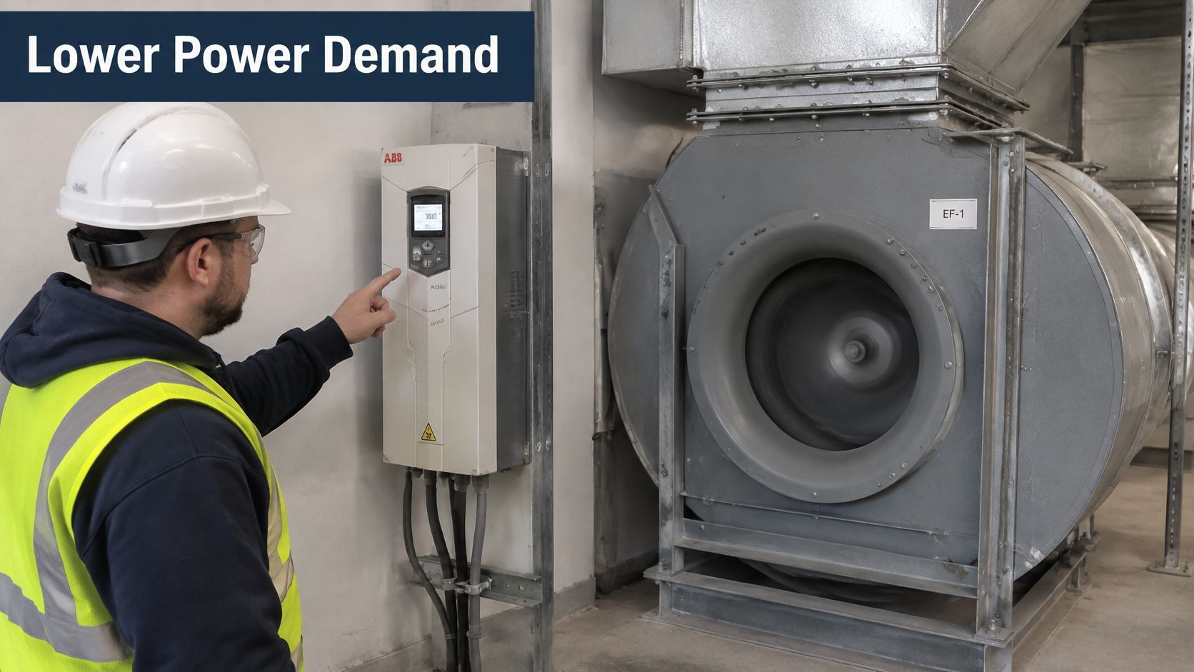
A fan or a centrifugal pump
On a variable-torque fan or centrifugal pump, torque falls with the square of speed and power falls toward the cube. Cut speed from full to about 80 percent and shaft power lands near half. That is why air and water are the usual payback stories. A throttling valve throws the difference away as pressure drop. Don't copy that savings story onto a machine that doesn't follow the cube.
A conveyor, extruder, or mill
A constant-torque conveyor, extruder, or mill uses the unit for torque, controlled acceleration, and fewer mechanical shocks. Power falls roughly with speed, not with the cube. Promise cubic savings here and the energy report will embarrass you at the first review. Size the unit for torque and overload, and for how often it must stop.
A weak bus full of six-pulse rectifiers
A drive is a nonlinear load. Its rectifier draws pulsed current and injects harmonics. Compliance is judged at the point of common coupling with IEEE 519, using total demand distortion against maximum demand current, not displacement power factor and not nameplate efficiency. Technical guidance on that framework, in an Eaton application note on IEEE 519, identifies voltage limits such as 5% total harmonic distortion and 3% for an individual harmonic. The same six-pulse drive can pass on a stiff utility bus and fail on a weak transformer or a generator.
Before you pick a line reactor, a passive filter, an active filter, or a multipulse or active-front-end architecture, measure demand current, individual harmonic orders, voltage THD, transformer impedance, and short-circuit ratio in a real operating state. The aim is to stop transformer heating, nuisance trips, capacitor stress, communication interference, and ugly voltage across the shared bus. Chasing a THD number at the drive terminals alone misses that.
A recurring trip or a hot motor may be the installation. Read the system measurements before you replace the unit.
<iframe width="100%" style="aspect-ratio: 16 / 9;" src="https://www.youtube.com/embed/3tLGtGyUeuU" frameborder="0" allow="autoplay; encrypted-media" allowfullscreen></iframe>Repair, Recondition or Replace Decision
The reliability lead's real choice starts when a unit is 7 to 15 years old, not when someone quotes a newer efficiency number. Recent IEA 4E testing of silicon-carbide variable-speed drives found that higher switching frequency helps only up to a threshold. For a 50 Hz industrial induction motor, raising SiC switching frequency above 10 kHz provided no additional system-efficiency benefit, because drive switching losses took over, according to the IEA 4E report on SiC variable-speed drives.
Build the comparison from a measured load profile, downtime if the cabinet must be shipped, harmonic and cooling headroom, motor insulation condition, and spare-part availability. Cybersecurity now sits in the same column. Rockwell reported IEC 62443-4-2 certification for VFDs in February 2025, so firmware support and network isolation belong next to capacitor life. A networked drive is an industrial asset, not only a power stage.
| Choice | When it fits | What you protect |
|---|---|---|
| Keep and maintain | Failures track dust, heat, or a sweaty room, and the power stack is still sound | Uptime, without a process change |
| Recondition serviceable subsystems | Mechanics and the main power path are sound, but caps, fans, or boards are aged | The installed unit, inside a planned shutdown |
| Replace the unit | Parts, safety ratings, or the process duty no longer fit | The process, accepting the outage and the new single-line |
Our System Upgrade work evaluates what can be reconditioned before anyone decides to replace an entire VFD system. We reconditioned high-voltage VFD systems on site at a tire plant in Rayong, Thailand, after nearly ten years in a carbon-black environment. At Shiheng Special Steel in 2026 we completed a full maintenance cycle for 43 Siemens S120 drives in under one month, covering environmental assessment, parameter backup, deep dust removal, thermal silicone replacement, board cleaning, insulation varnish, DC capacitor replacement, and component performance testing.
Before you call us, write down the brand, the exact model, rated power and voltage, the fault text as displayed, when it happens, and the room environment. The assessment starts from that sheet, not from the nameplate alone.
DUCHENG Industrial supports the full life of a variable frequency drive unit, from commissioning and preventive care through emergency troubleshooting, workshop repair, and on-site reconditioning of medium- and high-voltage cabinets that are hard to ship. If your single-line, cable, and grounding need the same attention as the power stack, visit DUCHENG Industrial and send the nameplate data with the fault text so the first visit starts from the system, not from a guess.