
Learn how a variable speed drive water pump matches flow to demand, when the energy savings are real, and how to select, commission and maintain one.
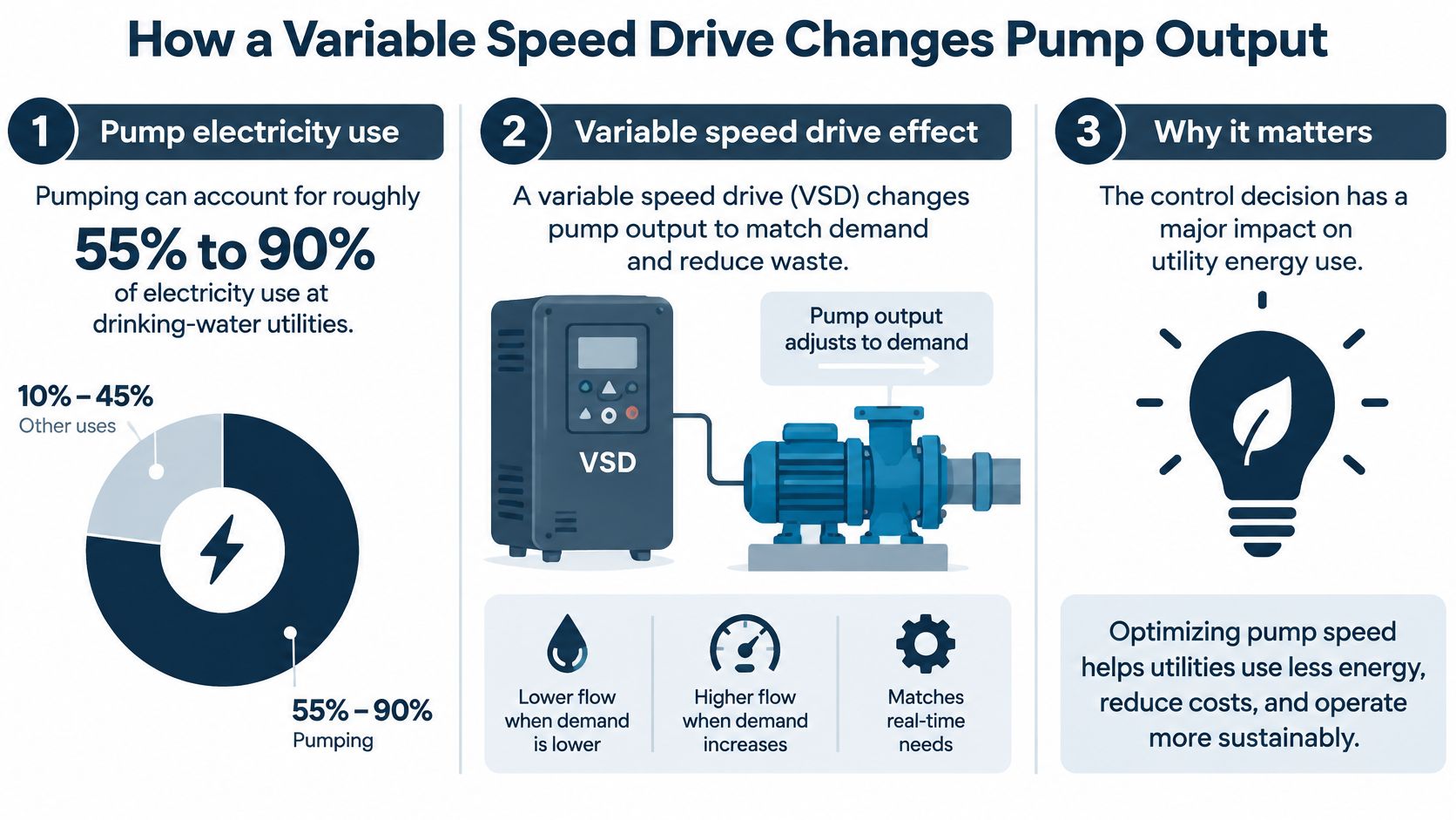
Pumping can account for approximately 55% to 90% of total electricity consumption at drinking-water utilities, according to the U.S. Environmental Protection Agency's energy conservation guidance. That makes pump control a major energy decision, not just an electrical upgrade. But a variable speed drive water pump saves energy only when the hydraulic duty gives it room to slow down.
The right assessment joins duty cycle, motor and drive sizing, pressure protection, and sensor setup. Buying the drive before checking those conditions can leave you with a more complicated system that still wastes energy.
Table of Contents
- How a Variable Speed Drive Changes Pump Output
- Affinity Laws and Why Small Speed Changes Cut Power
- Checking Whether a Pump Will Save Energy
- Sizing the Drive and Matching It to the Motor
- Setting Control Mode, Ramps and Commissioning
- Multi-Pump Sequencing and Field Examples
- Common Faults and Routine Maintenance
- Confirm Your Pump Case Before You Retrofit
How a Variable Speed Drive Changes Pump Output
A throttling valve controls flow a little like driving with the brake partly applied. The pump generates more head than the system needs, and the valve dissipates the excess through a pressure drop. A variable speed drive eases off the accelerator instead.
The drive changes the frequency and voltage supplied to the motor, allowing pump speed to follow demand. In a pressure-controlled booster, the controller adjusts speed using feedback from a pressure transducer. In a process-water application, the command might come from a flow controller or tank-level signal.
The illustration shows the relationship between pump demand and electrical input.
Pump control methods compared
| Control method | Motor speed | Power at reduced flow | Typical use |
|---|---|---|---|
| Throttling discharge valve | Fixed at full speed | Stays relatively high; valve dissipates excess head | Constant duty, simple systems |
| Bypass recirculation | Fixed at full speed | Power remains high; excess flow loops back to suction | Minimum-flow protection |
| On/off cycling | Full speed or stopped | Power consumed while running; frequent starts possible | Small tanks, low demand |
| Variable speed drive | Matches demand | Falls steeply where the hydraulic system permits | Fluctuating demand, booster sets |
The distinctions matter. A throttled centrifugal pump doesn't necessarily draw its full rated power, and bypass operation doesn't always mean nameplate power either. Actual input follows the pump's power curve and operating point. Fixed speed isn't the same as fixed power, but it limits how the operator can reduce unnecessary head.
On/off control can be sensible when storage lets a correctly selected pump run efficiently and then stop. A drive isn't automatically better than that arrangement. Bypass recirculation also has a legitimate protective role, although continuously recycling unnecessary flow wastes pumping effort.
First inspection: Identify what controls flow today, then write down the pressure, flow, or level requirement that a drive would actually maintain.
Check whether the existing setpoint serves the process or merely compensates for a restriction. A blocked strainer, partly shut isolation valve, or unsuitable impeller shouldn't become the basis for a new control strategy.
Affinity Laws and Why Small Speed Changes Cut Power
In an application documented by the American Council for an Energy-Efficient Economy and discussed in this engineering publication, throttling left the motor at 1,800 rpm and 8.5 kW, while VFD control at the same operating point used 1,180 rpm and 3.25 kW, a 62% reduction in instantaneous power demand. That's an operating-point result, not an annual savings guarantee.
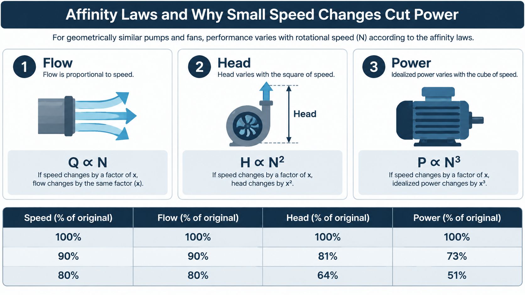
The explanation starts with the pump affinity laws. For the same impeller under geometrically similar operation, flow is approximately proportional to speed, head follows speed squared, and idealized power follows speed cubed.
The diagram summarizes those relationships.
Affinity-law ratios at reduced speed
The following values are calculated ideal ratios, using the affinity relationships above, not measured installation savings.
| Speed | Flow | Head | Idealized power |
|---|---|---|---|
| 90% | 90% | 81% | 73% |
| 80% | 80% | 64% | 51% |
| 70% | 70% | 49% | 34% |
| 60% | 60% | 36% | 22% |
| 50% | 50% | 25% | 13% |
These calculations explain why reducing speed can be much more effective than dissipating surplus pressure. They also explain why using a speed ratio alone to predict the electricity bill is risky.
Where the ideal calculation breaks down
The operating point sits at the intersection of the pump curve and system curve. Lowering speed moves the pump curve, but the system doesn't necessarily allow flow and head to follow the ideal ratios together. A pump moving water to a higher reservoir must still overcome the elevation difference.
Motor, drive, and pump losses also remain. At low output, those losses can represent a larger share of electrical input, while the pump may move away from its efficient operating region. Use the reduced-speed efficiency curves where available, rather than assuming unchanged efficiency.
This video provides a further visual explanation of variable-speed operation.
<iframe width="100%" style="aspect-ratio: 16 / 9;" src="https://www.youtube.com/embed/XwfC-k9UhQg" frameborder="0" allow="autoplay; encrypted-media" allowfullscreen></iframe>Check the operating point before claiming the saving. Confirm that the proposed speed still delivers the required head and stays inside the pump manufacturer's permitted operating range.
Checking Whether a Pump Will Save Energy
Start with a duty-cycle question: How much time does this pump spend delivering more flow or head than the process needs? A design duty point can't answer that. You need operating records covering normal production, low demand, and peak requirements.
For qualifying irrigation-pumping VFD projects, the Bonneville Power Administration's measure guide estimates 10% to 30% annual savings. That's a scoped planning benchmark, not a forecast for every industrial water pump.
Savings potential by pump system type
| System type | Savings potential | Why |
|---|---|---|
| Variable-demand pressure booster | High | Speed can follow demand and remove throttling losses |
| Irrigation with changing flow needs | Moderate to high | Changing zone requirements can provide useful speed variation |
| Constant-duty, fixed-flow pump | Low | Little speed change to exploit |
| Static-head-dominated lift | Low to moderate | Elevation head remains as speed falls |
| Oversized pump with throttle valve heavily closed | Potentially high | Evaluate valve correction or impeller trimming before drive selection |
A completely closed discharge valve isn't an energy-saving opportunity to operate through. It's a condition that requires checking the pump's allowable shutoff duration and minimum-flow protection.
Build a measured baseline
Log these signals on a common time base:
- Hydraulic duty: Flow, suction pressure, discharge pressure, tank level, and relevant valve positions.
- Electrical input: Motor current and measured input power. Current alone isn't a reliable energy measurement.
- Operating schedule: Runtime by hour, production state, starts, and tariff periods.
- Operating limits: Minimum flow, cooling and lubrication requirements, and pump efficiency at each relevant duty point.
Group the records into representative operating conditions. For each condition, estimate proposed electrical input using the required hydraulic duty and realistic pump, motor, and drive efficiencies. Multiply input power by operating hours, then add the conditions to estimate annual energy.
Calculate energy cost using the applicable tariff periods. Keep demand charges separate from energy charges, and include drive installation, controls, electrical mitigation, and maintenance in the payback assessment. The variable-speed drive energy-savings guide provides a useful framework for organizing that assessment.
Compare equal hydraulic service, not just lower electrical consumption.
After commissioning, compare matched flow, pressure, production conditions, and delivered volume. Track both total energy and energy per unit of water. A lower bill caused by reduced production isn't proof that the retrofit improved efficiency.
Sizing the Drive and Matching It to the Motor
A drive selected from the pump brochure's headline power can be undersized at the worst operating point. Size it against motor current, thermal limits, and the full hydraulic operating range; the energy case depends on whether the drive can meet the actual duty without pushing the motor or pump beyond its limits.
A practical sizing checklist
-
Match voltage and continuous current. Record rated voltage, full-load current, service factor, and inverter-duty suitability. After derating, the drive's continuous output current must cover the motor's requirement. Treat the service factor as a limit, not routine spare capacity.
-
Check the complete pump curve. Confirm absorbed power across the permitted flow range, including conditions with open valves or additional branches in service. Check the drive's acceleration-current capability and overload duration against its rating.
-
Set the minimum usable speed. A shaft-mounted fan cools less effectively as motor speed falls. Check motor thermal limits, pump lubrication, and minimum hydraulic duty before setting the speed floor. Independent motor ventilation may be needed.
-
Assess supply-side harmonics. Review requirements at the point of common coupling. Choose line impedance, reactors, filters, or a suitable rectifier arrangement based on the installation, not an assumption about the cabinet alone.
-
Check the installation environment. Record motor cable length, insulation suitability, grounding, enclosure protection, altitude, and cabinet temperature. Long motor leads can require an output reactor or voltage-rise filter; select these against drive and motor guidance.
Document selected ratings, derating assumptions, protection settings, and the permitted operating envelope before retrofit. That record also helps distinguish a sizing problem from an incorrectly set operating limit.
A larger drive won't correct an unsuitable motor, an overloaded pump, or inadequate cabinet cooling.
The commissioning engineer should be able to trace each programmed limit to a motor, pump, process, or electrical requirement.
Setting Control Mode, Ramps and Commissioning
Choose the controlled variable before tuning the drive. A stable motor-speed loop won't compensate for a pressure sensor installed in the wrong location or scaled incorrectly.
Match control to the hydraulic job
- Constant-pressure booster: Use pressure feedback with proportional-integral-derivative control. Confirm transducer range, engineering-unit scaling, setpoint, sleep behavior, and restart conditions.
- Flow-following or irrigation duty: Let speed follow a measured flow requirement or supervisory demand signal. Apply the pump and motor operating limits independently.
- Long pipeline with check valves: Coordinate pump acceleration and deceleration with valve movement and transient-pressure protection.
- Minimum-flow bypass system: Coordinate the speed floor and bypass operation so neither controller fights the other.
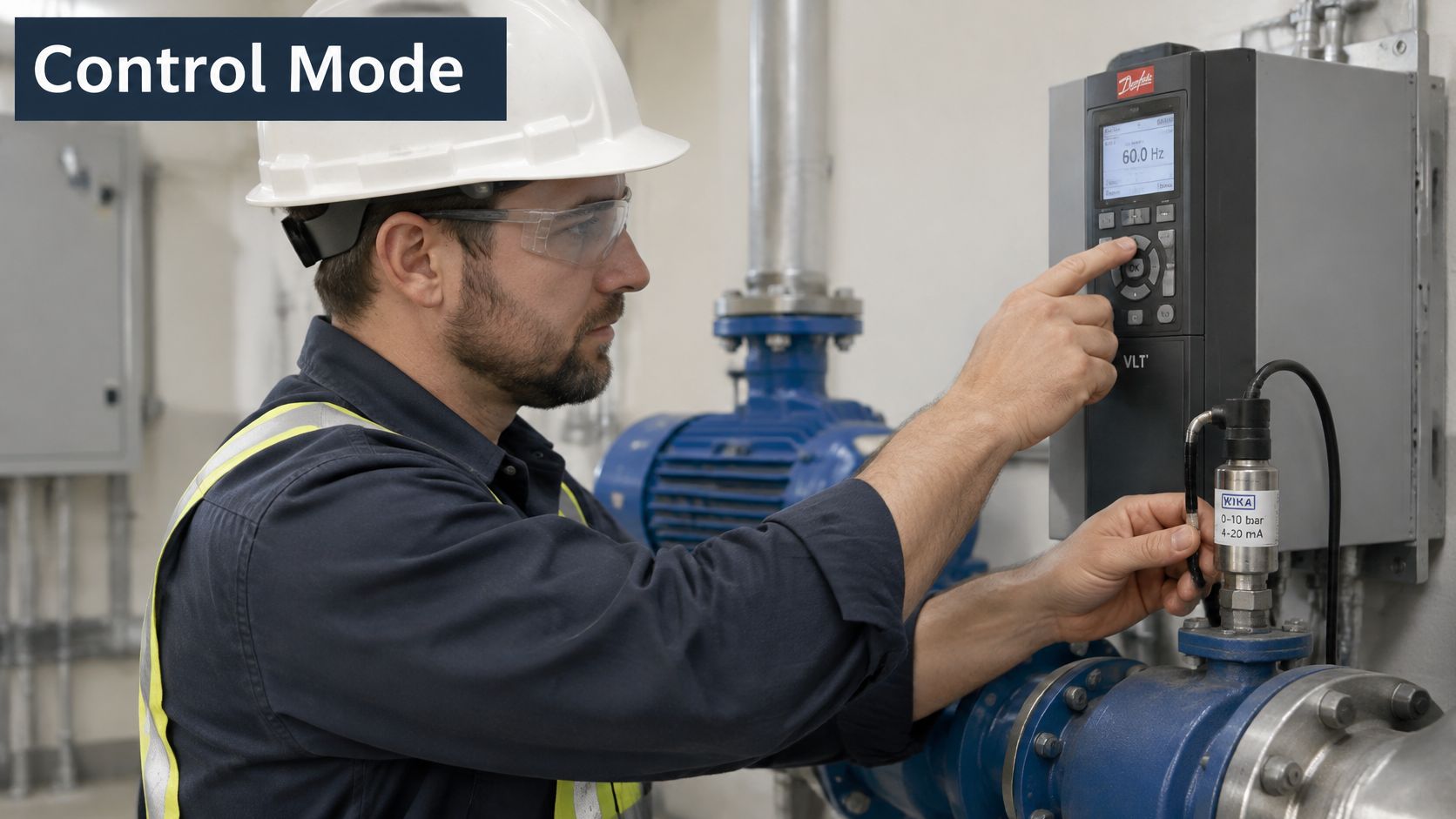
Install the transducer where it represents the pressure you need to control. Check its reading against an independent gauge, and inspect the sensing connection for blockage, trapped air, or excessive pulsation. Route signal wiring away from motor power cables and terminate shielding according to the control-system design.
The inspection should cover the complete control panel and feedback circuit.
Coordinate ramps with pressure protection
A published water-hammer study found that a conventional start sequence could produce an instantaneous outlet-pressure peak 39% above designed head, while coordinated pump-valve startup reduced the risk. A drive is therefore part of transient control, not a guarantee against water hammer.
Set acceleration and deceleration independently. Programmed deceleration isn't necessarily actual stopping time, particularly during a power failure when the drive may lose its ability to control the motor. Check-valve dynamics, reverse flow, pipe geometry, and tank behavior still matter.
Prove the sequence safely
Trend pressure, speed, current, and valve status during controlled starts, demand changes, and stops. Capture transients fast enough to reveal peaks that a slow supervisory trend could miss.
Verify sensor-failure fallback, alarm and trip thresholds, emergency-stop behavior, and generator transfer where installed. Test power-loss behavior only under an approved procedure with the necessary hydraulic protection and operational authorization.
Use the VFD startup checklist to organize electrical checks and handover records. Save the final parameters and trend files together, so maintenance staff have a usable baseline.
Multi-Pump Sequencing and Field Examples
In a pump station, the energy decision is often which pumps should run, and at what speeds. Running every available pump slowly can be less efficient than operating a smaller combination near suitable duty points.
A Hong Kong Polytechnic University study found 10% annual energy-saving potential from optimized variable-speed pump sequencing, while four-day field tests measured 15% savings against a rule-based baseline. The annual estimate and short field-test result are different measures, not interchangeable promises.
A booster-station scenario
Consider a hypothetical station with a fixed-speed base pump and lead and lag variable-speed pumps. The base pump is useful only while demand can absorb its output without excessive pressure or recirculation.
| Demand condition | Proposed action | What the engineer must verify |
|---|---|---|
| Stable base demand | Run the fixed-speed pump | Its duty point remains efficient and hydraulically acceptable |
| Demand rises | Lead drive carries the changing load | Pressure stays stable within the permitted speed range |
| Lead pump approaches its useful upper limit | Start the lag drive and redistribute load | Combined operation improves capacity without pushing either pump outside its envelope |
| Demand falls | Unload and stop the lag pump | Remaining pumps can carry demand without a pressure dip |
| Demand drops below base-pump capacity | Remove the base pump when appropriate | The variable-speed combination can serve low demand efficiently |
Don't start the lag pump on speed alone. Confirm sustained demand, pressure error, available capacity, and the expected operating points after staging. Add suitable hysteresis and timing to prevent repeated starts and stops near a staging boundary.
Compare the station, not individual drives
Log pump status, runtime, speed, header pressure, delivered flow, electrical energy, and alarms. Calculate station energy per cubic metre, including all operating pumps rather than just the variable-speed units.
Keep runtime balancing separate from energy optimization. Alternating the lead pump can distribute wear, but equal hours don't prove minimum energy consumption.
Compare the new strategy with the existing baseline under matched demand and pressure requirements. Include low-demand periods and staging transitions, not just steady operation at the easiest test point. A sequence that saves energy but repeatedly drops header pressure isn't ready for handover.
Common Faults and Routine Maintenance
Common VSD pump faults and fixes
| Symptom | Likely cause | Fix |
|---|---|---|
| Overcurrent trip on start | Ramp too fast or pump seized | Check free rotation under isolation; lengthen acceleration only after checking mechanical load |
| Pressure hunting | PID gains too high or sensor noise | Verify feedback quality, then retune gains and filtering |
| Motor overheats at low speed | Too little cooling airflow | Check motor cooling; raise minimum speed or provide suitable independent ventilation |
| Nuisance low-pressure alarms | Transducer fault or wrong range | Verify actual pressure, signal scaling, sensor range, and calibration |
| Pressure spike on stop | Check-valve slam or fast stop | Review deceleration and coordinate valve closure using pressure trends |
Treat the table as a starting point, not permission to change settings blindly. Lengthening a ramp won't free a seized pump, and increasing an alarm delay can conceal a real loss of water supply.
Preserve the fault record before resetting. Save the displayed code, operating speed, current, pressure, command state, and event sequence. A trip during acceleration needs a different investigation from a trip after prolonged low-speed running.
Keep the baseline useful
Build routine inspections around the installed environment and the manufacturers' maintenance requirements:
- Cooling path: Inspect drive fans, filters, heat sinks, and cabinet ventilation. Remove contamination using approved methods rather than blowing conductive dust deeper into the equipment.
- Electrical condition: Inspect cable terminations, grounding, discoloration, and heat damage during a properly isolated shutdown. Use specified tightening procedures, not indiscriminate retightening.
- Feedback accuracy: Compare the pressure transducer with a reference instrument. Inspect sensing ports and signal connections before changing controller tuning.
- Mechanical protection: Inspect check valves, isolation valves, bypass operation, and pressure-tank condition. Verify tank precharge using the correct isolation and depressurization procedure.
- Configuration control: Back up parameters after approved changes and record why each limit or control setting changed.
A practical maintenance program includes regular operating trend reviews and a planned shutdown inspection. Set the interval according to contamination, duty severity, equipment condition, and production risk rather than applying the same calendar to every installation.
Compare pressure, current, speed, and temperature at matched operating conditions. Rising current at the same duty may justify checking mechanical drag or hydraulic changes; unstable pressure with a steady command may point toward valves or feedback rather than a failed drive.
Don't perform insulation-resistance testing through connected drive electronics. Follow the isolation and discharge procedure, and disconnect equipment as required by the manufacturer.
Many apparent drive faults are system faults. Inspect the pump, motor, sensor, valves, tank, and electrical supply as a connected installation before replacing components.
Confirm Your Pump Case Before You Retrofit
Before authorizing an order, require clear answers to these gate questions:
- Demand evidence: Do logged flow and pressure show useful demand variation, rather than just a design duty point?
- Energy evidence: Does the proposed estimate reconcile with measured baseline energy and delivered hydraulic service?
- Reliability evidence: Does the control sequence cover valves, ramps, sensors, protection, and fallback behavior?
An unanswered question means the engineering package isn't ready. Correct the relevant hydraulic restriction, impeller selection, instrumentation, or control logic before committing to equipment.
Prepare a representative operating log, motor nameplate details, pump curves, supply information, and the chosen control mode. DUCHENG Industrial's VFD Master supports engineering pre-selection of low-, medium-, and high-voltage drive projects with real-time sizing, a copyable summary, and print/PDF export. Treat pre-selection as a documented starting point, not final approval of the installation.
For a service review, include the drive brand, exact model code, rated power and voltage, the fault code exactly as displayed, when it occurs, and the operating environment. Those details make the request actionable.
DUCHENG Industrial provides multi-brand VFD commissioning, preventive maintenance, troubleshooting, repair, and on-site reconditioning for industrial facilities. Visit DUCHENG Industrial to request support for your pump-drive project, bringing the motor details, hydraulic duty records, and control requirements so the review starts with the actual installation.