
Explore a comprehensive reference of VFD fault codes with meanings, causes, immediate mitigations, and troubleshooting tips for major industrial drive brands.
A production pump stops, the process line goes quiet, and the VFD display shows a short code that means little without the correct manual. Someone resets the drive, it runs briefly, then trips again. That reset loop wastes time because the active alarm is only the visible symptom. VFD fault codes become useful when technicians connect the code, operating conditions, and stored sequence to a likely underlying cause.
A disciplined response starts with safe isolation, preserves the drive's diagnostic information, and separates electrical, mechanical, thermal, environmental, and control causes. The same method works across different drive families even though the code numbers themselves vary. Use the displayed message as an entry point, not as proof that the drive is defective.
Table of Contents
- Introduction to VFD Fault Codes
- Categorizing VFD Fault Codes
- Detailed Fault Code Entries
- Interpreting Fault History and Trends
- Multi-Brand Fault Code Comparison
- Quick Reference Lookup Table
- Practical Troubleshooting Examples
- Glossary of Terms
- Related Resources
Introduction to VFD Fault Codes
A variable frequency drive fault code is a protective diagnostic message. The drive monitors current, voltage, temperature, motor behavior, feedback, and control signals. When a measured condition exceeds its configured limit, the drive may remove output power or block a restart to protect its power stage, the motor, and connected equipment.
The displayed code answers one question: what condition caused the trip? It doesn't automatically answer the more important question, why did that condition occur? An overcurrent trip can follow a jammed machine, a damaged cable, an incorrect motor setting, or an acceleration ramp that doesn't suit the load. An overtemperature message can reflect blocked airflow, a failed fan, high cabinet heat, or ageing components.
Preserve evidence before resetting
Before pressing reset, record:
- The exact code: Include the full message, auxiliary code, and drive series if shown.
- The operating state: Note whether the trip happened at startup, during acceleration, at steady speed, during deceleration, or after extended operation.
- The surrounding conditions: Record load status, recent maintenance, cabinet condition, unusual noise, process changes, and whether other equipment lost power.
- The stored values: Capture current, voltage, frequency, speed, and temperature when the drive provides them.
Fault-code numbering isn't universal across major VFD families. Each manufacturer uses its own structure, so the first lookup must match the exact drive series and firmware, as explained in this cross-brand VFD troubleshooting guidance.
Treat the fault as a decision point
A good technician doesn't ask only, “How do I clear this code?” The better questions are:
- Was the event sudden or progressive?
- Did another fault appear before it?
- Does the same fault return under the same operating condition?
- Can the motor, cable, machine, supply, and control network be tested separately?
This approach reduces unnecessary drive replacement. It also prevents a dangerous habit, repeated resetting, from hiding an intermittent supply issue, insulation problem, cooling failure, or mechanical restriction.
Practical rule: Read and record the fault history before resetting. A live code is an alarm. The sequence around it is evidence.
Categorizing VFD Fault Codes
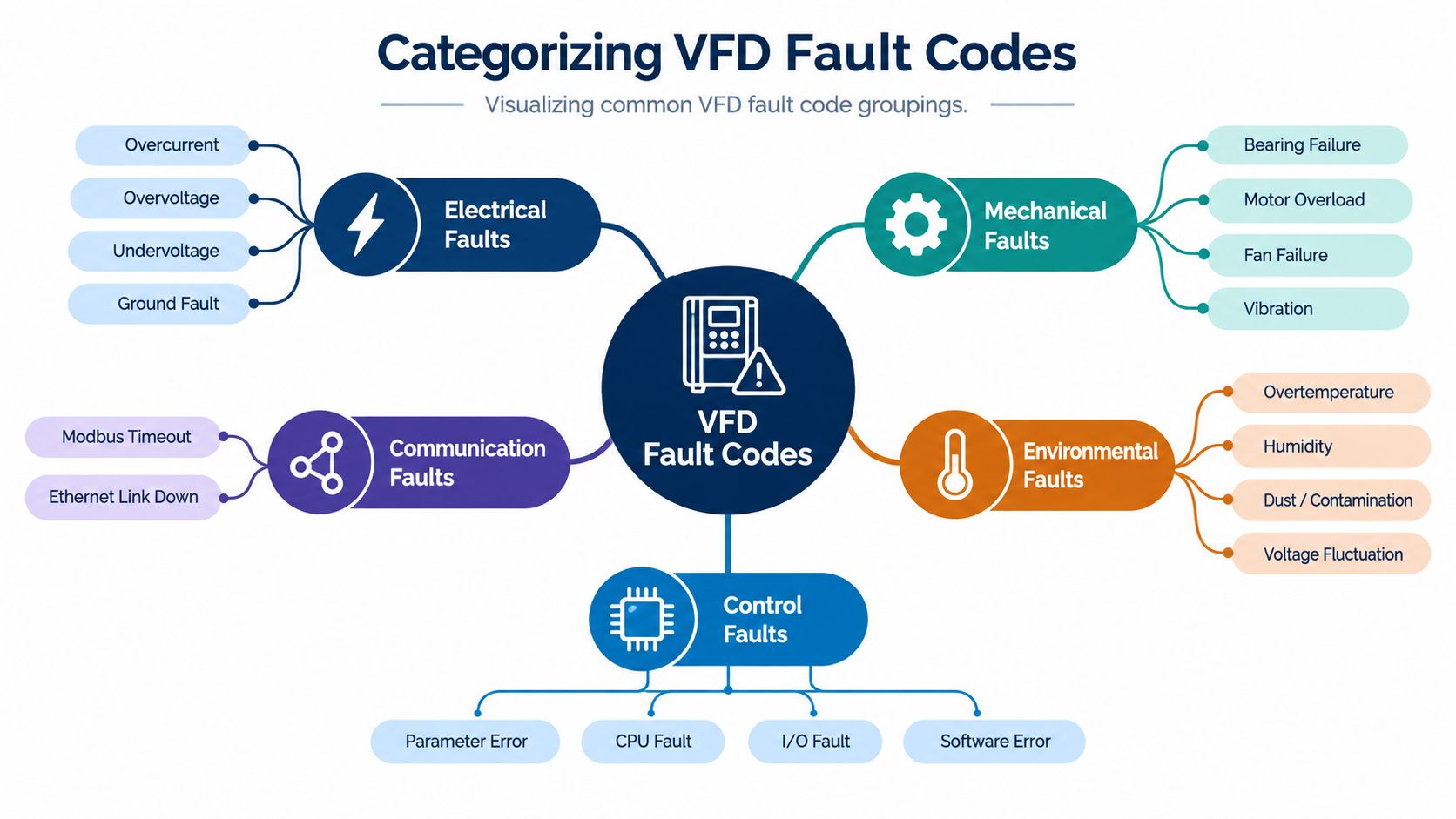
Grouping VFD fault codes by their underlying cause makes troubleshooting faster than following code numbers one by one. A code's label may differ between drive families, but the physical problem usually belongs to a recognizable diagnostic class.
Electrical faults
Electrical codes include overcurrent, overvoltage, undervoltage, phase loss, short circuit, and ground fault. Start by asking whether the abnormal condition appears on the input side, the DC link, or the motor output. A supply disturbance points toward incoming power, while a fault that appears only when the motor is connected shifts attention to the cable, motor, or load.
Ground faults deserve particular care. IEEE Std 43-2013 provides common insulation-resistance benchmarks, including 5 MΩ corrected to 40°C for most modern random-wound motors rated below 1 kV and 100 MΩ for form-wound coils typically used in medium-voltage machines above 1 kV. Those values are given in the IEEE insulation-resistance reference. Test the motor and cable with the drive disconnected, and follow the equipment manufacturer's safety procedure.
Mechanical faults
Mechanical causes include stall, overload, jam, excessive inertia, misalignment, blocked flow, and bearing resistance. A drive can correctly report excessive current even when its own electronics are healthy. Check whether the shaft turns freely, whether a pump or fan is obstructed, and whether the process load changed.
Thermal and environmental faults
Thermal messages may involve the motor, drive heatsink, cabinet, or cooling system. Environmental contributors include dust, conductive contamination, moisture, high ambient heat, restricted ventilation, and salt exposure. These conditions often develop gradually, which makes fault history especially valuable.
Communication and control faults
Communication faults include network timeout, lost I/O, feedback failure, and external interlock signals. Control faults can also result from incorrect command sources, missing enables, unsuitable ramp settings, or conflicting references. Confirm what the drive was commanded to do before assuming the network hardware failed.
A practical classification question is simple: what changed first, the electrical measurement, the machine behavior, the temperature, or the command signal? That first change usually narrows the investigation more effectively than the code label alone.
Detailed Fault Code Entries
The exact identifier depends on the drive family, so use the manufacturer's manual for the final code definition. The entries below use common fault families and focus on the checks that distinguish similar symptoms.
Overcurrent
Meaning: Output current exceeded the drive's instantaneous protection limit.
Likely causes: A short circuit, damaged motor cable, winding fault, jammed shaft, excessive load torque, incorrect motor data, or an acceleration ramp that demands current too quickly can all produce overcurrent. The trip timing matters. A fault at the instant of starting points toward a wiring, motor, mechanical, or ramp problem. A fault during a sudden process change suggests a load event.
Immediate action: Don't keep resetting. Isolate the machine, inspect the motor and cable for visible damage, and confirm that the driven equipment can move safely.
Deeper checks:
- Compare motor nameplate data with the drive parameters.
- Inspect motor terminals, cable glands, and output connections for looseness or damage.
- Check the machine for a jam, seized bearing, blocked pump, or excessive process load.
- Review acceleration time and torque-related settings.
- Test motor and cable insulation separately, with the cable disconnected from the drive and the circuit safely isolated.
A short, sharp current spike and a sustained high-current condition require different responses. Increasing the acceleration time may help a correctly wired, mechanically sound machine, but it won't repair a shorted cable or a seized load.
Overvoltage
Meaning: The DC link or input voltage exceeded the drive's permitted level.
Likely causes: Rapid deceleration, an overhauling load, regenerative energy, high incoming voltage, or a braking system that isn't correctly selected or connected.
Immediate action: Review when the trip occurred. If it happens during stopping, avoid shortening the deceleration ramp until the regenerative energy has been evaluated.
Deeper checks:
- Measure incoming voltage under the relevant operating condition.
- Review the deceleration profile and machine inertia.
- Check braking components, wiring, and configuration where installed.
- Determine whether the load drives the motor during part of the cycle.
- Look for a pattern tied to a particular stop, speed, or process stage.
A longer deceleration ramp is often the simplest correction, but it may conflict with production timing or safety requirements. A braking solution can preserve the required cycle, yet it adds components that need correct sizing, installation, and maintenance.
Undervoltage
Meaning: The drive detected insufficient input or DC-link voltage.
Likely causes: Supply dips, loose terminals, upstream switching problems, phase loss, a weak distribution point, or unstable generator operation can cause undervoltage. A drive may trip even when the supply appears normal during a later inspection.
Immediate action: Preserve the trip record and inspect the input circuit before restarting under full load.
Deeper checks:
- Measure all input phases at the drive terminals, not only at the upstream panel.
- Inspect fuses, disconnects, contactors, lugs, and cable terminations.
- Correlate the trip with other equipment starting or stopping.
- Check whether the fault occurs during high-load periods.
- Compare the drive's recorded voltage value with independent measurements where possible.
Do not solve repeated undervoltage trips by increasing protection tolerances. That can hide a deteriorating connection and expose the drive or motor to unstable operation.
Ground fault
Meaning: The drive detected current flowing from the motor circuit toward ground.
Likely causes: Motor insulation breakdown, cable damage, moisture, contamination, incorrect termination, or a grounded conductor can trigger the fault. In medium-voltage equipment, the risk and test procedure require qualified personnel and site-specific controls.
Immediate action: Lock out the equipment and separate the motor circuit from the drive before insulation testing. Never apply an insulation tester through the connected VFD output stage.
Deeper checks:
- Test the motor and cable independently.
- Inspect cable routes, glands, junction boxes, and motor terminal boxes.
- Check for moisture, conductive dust, oil, or chemical contamination.
- Compare readings across phases and track changes during planned maintenance.
- Use the applicable insulation-resistance benchmark and the equipment manual together.
A ground-fault code isn't proof that the drive has failed. It often identifies a fault in the motor circuit that the drive detected quickly enough to protect itself.
Overload and motor thermal
Meaning: The motor has drawn excessive current for too long, or the drive's motor model or sensor indicates an overheating condition.
Likely causes: Excessive mechanical load, blocked airflow, low-speed operation with inadequate motor cooling, wrong motor data, repeated starts, or process conditions outside the original design.
Immediate action: Let the motor and machine reach a safe condition. Check actual load and motor temperature before changing thermal settings.
Deeper checks:
- Verify rated current, voltage, frequency, speed, and power parameters.
- Compare operating current with the motor's nameplate information.
- Inspect the driven machine for friction, blockage, or changed process resistance.
- Check the motor cooling path, especially during low-speed operation.
- Look at the fault sequence for preceding overcurrent or stall events.
Raising the overload threshold can keep production running briefly, but it removes protection rather than fixing the load. Correct the mechanical or configuration issue first.
Drive overtemperature
Meaning: The drive's power section, heatsink, cabinet, or monitored internal point became too hot.
Likely causes: Blocked filters, failed fans, fouled heatsinks, restricted cabinet airflow, high ambient temperature, excessive switching demand, or ageing cooling components.
Immediate action: Check whether fans are operating and whether air can enter and leave the enclosure. Don't open energized equipment unless the task is covered by an approved electrical safety procedure.
Deeper checks:
- Inspect filters, vents, heatsinks, and fan bearings.
- Check cabinet temperature and nearby heat sources.
- Review whether the fault appears after extended operation rather than at startup.
- Look for contamination patterns inside the enclosure.
- Confirm that the drive's installation clearance and cooling arrangement remain suitable.
An overtemperature fault that gradually becomes more frequent is a maintenance signal. Replacing the drive without cleaning the enclosure or correcting airflow can produce the same failure in the replacement unit.
Phase loss
Meaning: The drive detected a missing or seriously unbalanced input or output phase.
Likely causes: Blown fuses, loose terminals, damaged contactors, cable faults, output switching equipment, or a motor connection problem can be involved.
Immediate action: Isolate the circuit and inspect the supply path and motor connections. Check for heat discoloration at terminals, which may indicate a high-resistance connection.
Deeper checks:
- Measure phase-to-phase voltage at the drive input under load.
- Inspect upstream protective devices and switching equipment.
- Check output terminals and motor cable continuity after isolation.
- Review whether the event coincides with another machine's switching activity.
- Verify that no contactor is switching the drive output while the drive is running.
Communication loss and feedback errors
Meaning: The drive stopped receiving expected data from a controller, network, encoder, or other feedback device.
Likely causes: Damaged cabling, loose connectors, an offline controller, address or parameter mismatch, electrical noise, unsuitable timeout settings, or a failed feedback device.
Immediate action: Determine whether the drive stopped because the command link disappeared or because the motor feedback became invalid. Record the network state and any related control alarms before cycling power.
Deeper checks:
- Inspect connectors, cable shielding, termination, and routing.
- Confirm the controller is powered and sending the expected command.
- Check drive communication parameters and timeout behavior.
- Compare the event sequence with cabinet work or nearby switching activity.
- Test feedback wiring and sensor supply separately from the drive.
A communication fault can be a control-system problem, not a power-stage failure. The correct remedy may be cable repair, configuration correction, network reliability work, or a change to the fault response policy.
Interpreting Fault History and Trends
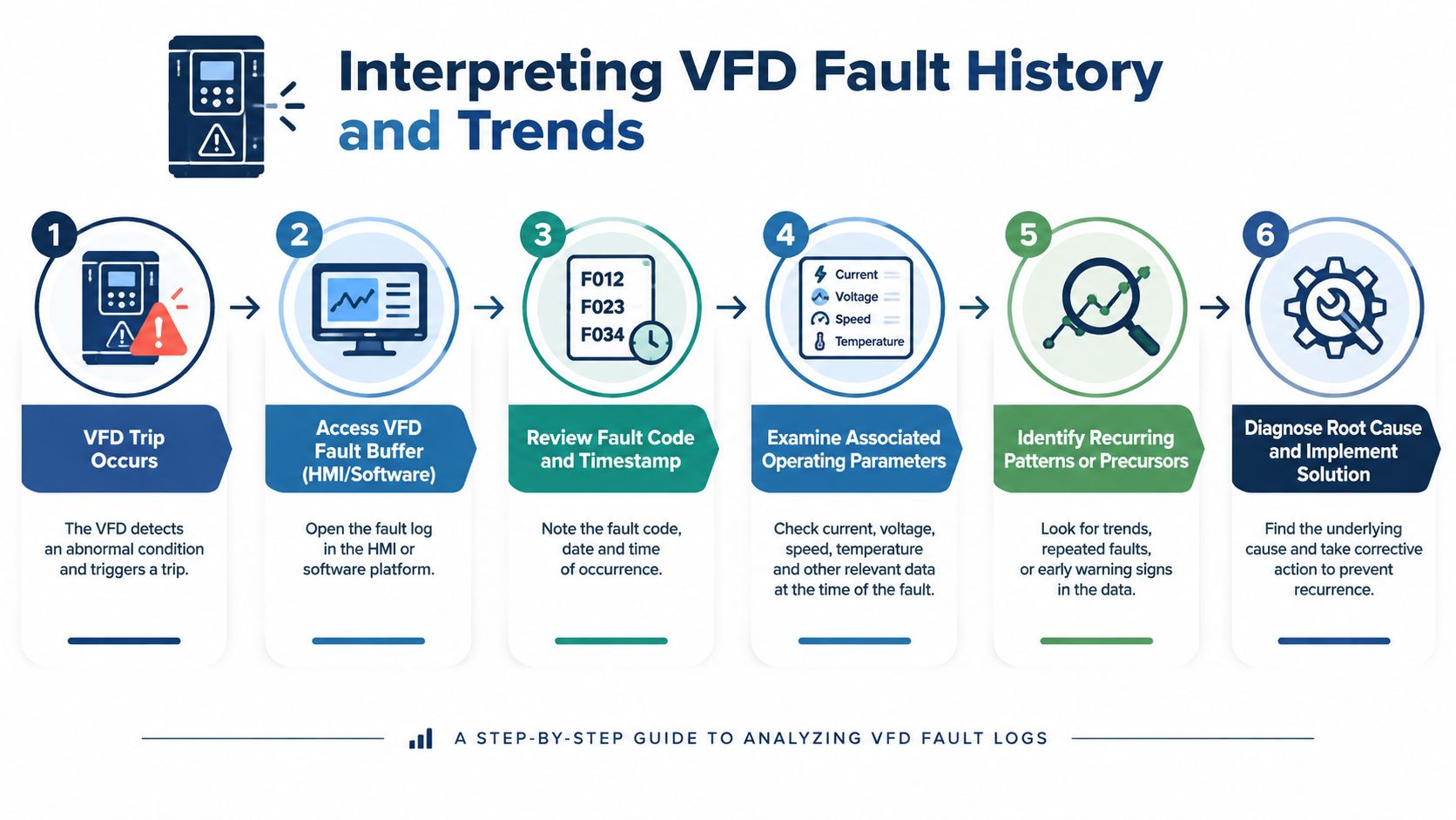
A fault buffer turns a VFD from a device that reports one alarm into a record of operating behavior. One major drive platform lets operators scroll through the eight most recent messages, while another industrial drive family stores 32 time-stamped fault codes in its buffer, as documented in this drive fault-history bulletin.
Read the sequence, not just the last entry
Start with the oldest relevant event and move toward the final trip. Suppose the sequence shows a communication warning, then a speed-reference loss, then an undervoltage event. That order suggests a broader control or supply disturbance. If it shows repeated overcurrent events at startup with no preceding warning, inspect the motor circuit and machine first.
Record the same fields for every event:
- Time and date: Look for shift, process, or weather correlations.
- Fault family: Group equivalent physical conditions even when labels differ.
- Operating values: Compare current, voltage, frequency, speed, and temperature.
- Operating phase: Mark startup, acceleration, steady state, deceleration, and stop.
- Precursor events: Identify warnings that repeatedly appear before the trip.
Separate transient events from chronic patterns
A one-off event may follow an unusual load disturbance or supply interruption. A recurring code at the same process stage deserves a planned root-cause investigation. Repeated overcurrent or overtemperature events can indicate ageing infrastructure, contamination, cooling degradation, or process instability rather than a failed drive alone, a point reinforced by current drive modernization and predictive-maintenance guidance.
Don't erase the evidence with uncontrolled resets. After each intervention, document what changed and whether the next event moved, disappeared, or returned under the same condition.
<iframe width="100%" style="aspect-ratio: 16 / 9;" src="https://www.youtube.com/embed/saJbl7UvL9o" frameborder="0" allow="autoplay; encrypted-media" allowfullscreen></iframe>Use the history to prioritize work. A single old fault may need observation, while a tight cluster of related faults should drive immediate inspection of the common upstream cause.
Multi-Brand Fault Code Comparison
Cross-brand troubleshooting fails when teams treat numeric codes as universal. The same physical condition can have different identifiers, message formats, auxiliary values, and reset behavior across drive families. Even within one manufacturer's range, series and firmware can change the code structure.
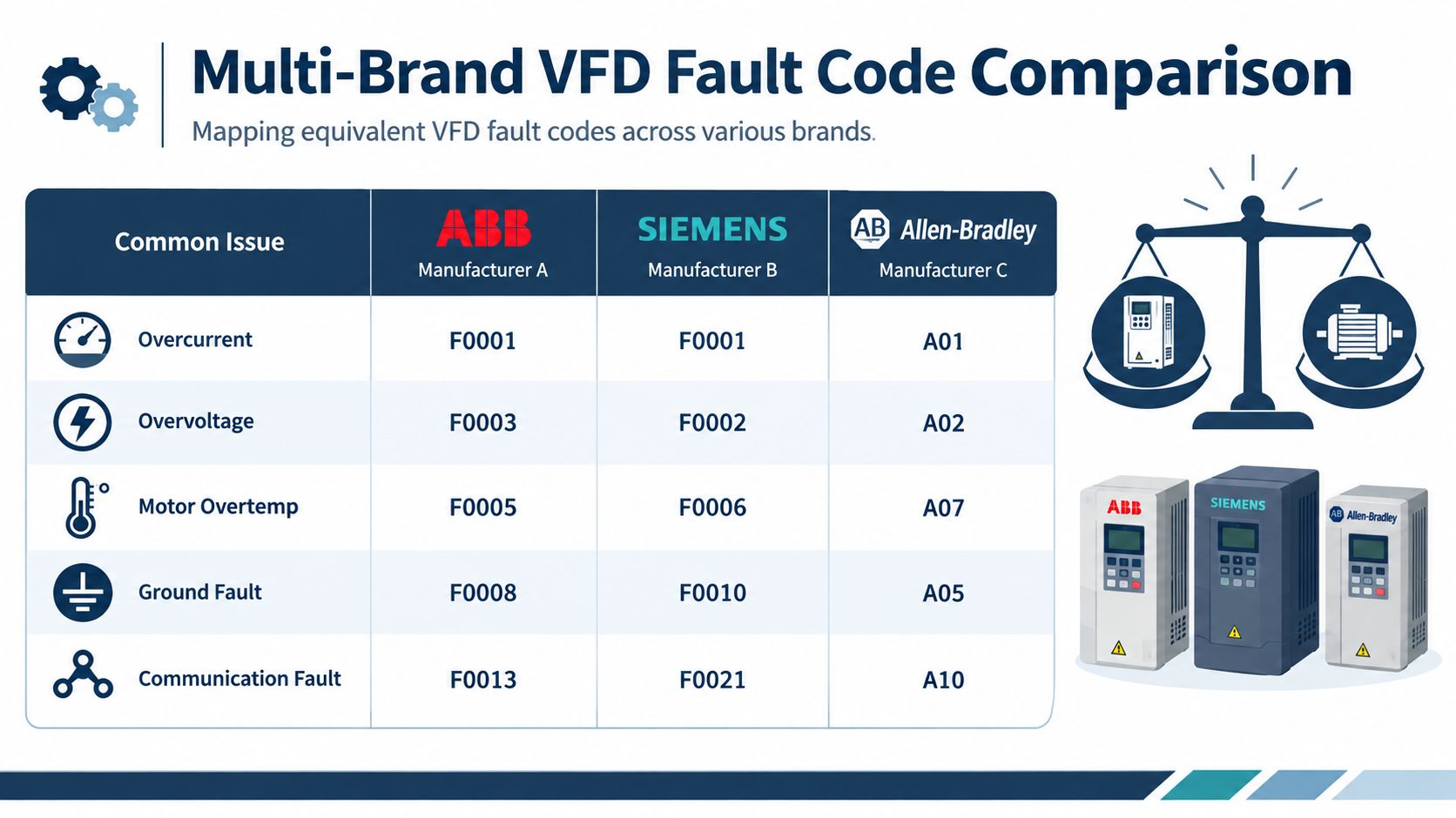
Map by physical cause
Build your plant reference around fault families rather than memorized numbers. A useful cross-brand worksheet contains:
| Field | What to record |
|---|---|
| Drive identity | Manufacturer, series, rating, firmware |
| Displayed message | Exact code and text |
| Physical family | Overcurrent, voltage, thermal, mechanical, communication, or control |
| Trip condition | Startup, acceleration, running, deceleration, or stop |
| Captured values | Current, voltage, speed, frequency, temperature |
| First checks | Supply, motor circuit, machine, cooling, or network |
| Recovery decision | Controlled reset, deeper test, repair, or replacement review |
This structure lets a supervisor assign the right technician even when the plant has multiple drive families. It also improves handover because the next person receives a diagnosis path rather than an isolated number.
Avoid false equivalence
A code labeled “overload” may represent a motor thermal model, an output-current duration limit, or a process-specific protection function. A “communication fault” may refer to a fieldbus timeout, a keypad link, an encoder, or a configured external input. Read the exact manual before translating the message.
For a repeatable reporting process across brands, use this multi-brand fault-code reporting workflow. The report should preserve the original code and add the normalized physical category. Never replace the original identifier with a guessed equivalent.
What belongs in a site standard
A site-wide procedure should require technicians to capture the exact drive identity, fault history, trip conditions, and measured values before reset. It should also define which tests require isolation, which tests must be performed by qualified personnel, and when a specialist review is mandatory.
This approach takes longer than copying a code into a generic list, but it prevents incorrect substitutions and repeated misdiagnosis. The trade-off is worthwhile in multi-vendor plants because consistent evidence matters more than a universal-looking table.
Quick Reference Lookup Table
Use this table as a first-response aid, not as a substitute for the exact drive manual. The labels are fault families, so the displayed identifier may differ by manufacturer and series.
| Fault Code | Meaning | Immediate Mitigation |
|---|---|---|
| OC | Sudden output overcurrent | Stop resetting. Check the load, motor cable, terminals, insulation, and acceleration setting. |
| OV | DC-link or input overvoltage | Review supply and deceleration conditions. Check regenerative energy and braking arrangements. |
| UV | Undervoltage | Check input phases, fuses, terminals, and upstream supply behavior under load. |
| OL | Sustained motor overload | Inspect the machine, motor data, cooling, and actual operating load. |
| OH | Drive or motor overtemperature | Check fans, filters, heatsinks, cabinet airflow, and ambient heat. |
| GF | Ground or earth fault | Isolate the drive, then test motor and cable separately using the approved procedure. |
| PH | Phase loss | Inspect input protection, terminals, contactors, output connections, and cable continuity. |
| COM | Communication or feedback loss | Check network power, cabling, connectors, controller status, feedback wiring, and timeout settings. |
The first action should preserve evidence. If the same family returns, move from reset-based recovery to a documented root-cause investigation.
Practical Troubleshooting Examples
A high-speed fan trips on overtemperature after running for an extended period. The drive cabinet looks intact, but the cooling fan is weak and the filter is loaded with dust. The correct response isn't to increase the thermal limit. Isolate the equipment, restore airflow, inspect the heatsink, verify fan operation, and compare future trips with cabinet temperature and operating duration.
A pump drive reports intermittent ground faults. The alarm appears after wet cleaning, then disappears during dry operation. Technicians separate the motor cable from the drive, inspect junction boxes and glands, and test the motor circuit independently. Moisture or contamination becomes more credible than a drive power-stage failure, and the repair plan can focus on the affected cable route, termination, or motor enclosure.
A packaging line stops on serial communication loss. The drive runs normally under local control, but the fault returns when the controller resumes network command. The team checks link status, connectors, shielding, controller availability, and timeout parameters before replacing the drive. The sequence shows that the power section is operating and the interruption belongs to the command path.
These examples illustrate why DUCHENG Industrial's VFD troubleshooting guide organizes diagnosis around fault families and first checks. Recurring overcurrent or overtemperature events may point to ageing components or contamination rather than a drive defect alone, which affects the decision between cleaning, reconditioning, repair, and replacement.
Glossary of Terms
DC link: The internal direct-current section between the input rectifier and inverter. Its voltage rises when regenerative energy returns from the motor and falls when the incoming supply is interrupted or weak.
Torque limit: A configured boundary that restricts the torque the drive will request from the motor. A limit can protect equipment, but an unsuitable value may cause poor acceleration or stall-related alarms.
Ground fault: An unintended electrical path from a conductor or winding to ground. In a motor circuit, insulation damage, moisture, contamination, or cable failure can create the path.
PID control: A feedback control method that adjusts drive output to maintain a process variable, such as pressure or flow. Incorrect feedback scaling or unstable tuning can produce speed changes that appear as load-related faults.
Thermal overload: A protective response to excessive heating over time. The drive may calculate motor heating from current and operating conditions or receive information from a temperature sensor.
Fault buffer: Nonvolatile or retained diagnostic memory that stores previous fault messages and, on some drives, timestamps and operating values. It supports sequence analysis after the live display has changed.
Trip: A protective shutdown or output inhibit initiated by the drive. A trip isn't necessarily evidence of an internal drive failure.
Regeneration: The condition in which the motor returns energy to the drive, often during rapid deceleration or when the machine drives the motor.
Insulation resistance: The resistance between conductors and ground, measured with an approved insulation tester after the drive has been disconnected and the circuit made safe.
Preventive maintenance: Planned inspection, cleaning, testing, and replacement work intended to address developing risks before they cause an unplanned trip.
Related Resources
Start with the exact OEM manual for the drive series and firmware. Use its fault-code appendix, parameter descriptions, safety instructions, and fault-history procedure rather than relying on a generic code list.
For insulation and grounding work, consult the IEEE rotating-machine insulation reference. For fault-buffer practice, review the documented drive fault-history procedure. Keep a site worksheet that records the drive identity, original code, history, operating state, measurements, corrective action, and restart result.
When an event remains intermittent or the repair decision is unclear, provide a qualified service team with the original fault record, nameplate information, photographs, and test results. That evidence supports a safer decision between controlled recovery, workshop repair, on-site reconditioning, and replacement.
DUCHENG Industrial supports VFD commissioning, structured fault diagnosis, repair, preventive maintenance, on-site reconditioning, spare-parts matching, and modernization assessments for industrial drive systems. Visit DUCHENG Industrial with the drive brand, model, fault code, and available fault-history details to discuss the next diagnostic step.