
Circuit breakers high voltage protect equipment and personnel. Learn how to select, install, and maintain them safely for reliable power systems.
A rolling-line drive trips during a production run, and the fault indication points upstream. The incoming breaker opened, but the key question is whether it cleared the fault selectively or took the transformer, bus, and healthy drive feeders offline with it. If the breaker's interrupting duty, protection settings, or mechanism condition don't match the system, a local electrical fault can become a plant-wide outage.
That's why circuit breakers for high-voltage systems deserve attention beyond procurement and nameplate review. They form a critical boundary between the utility supply and a plant's distribution network, and their response affects what happens to transformers, switchgear, VFDs, and motors when abnormal current flows. The practical job is to choose and coordinate the breaker, then maintain it in a way that gives the site defensible evidence for keeping it in service.
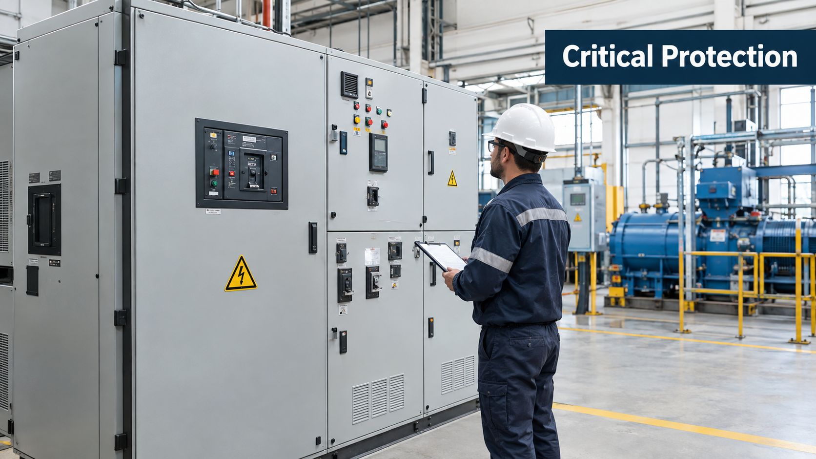
Table of Contents
- Why High Voltage Circuit Breakers Matter on Industrial Sites
- How High Voltage Breakers Interrupt a Fault
- Comparing SF6, Vacuum, and Air Breaker Technologies
- Ratings and Standards That Actually Matter
- Selecting and Coordinating Breakers with MV and HV Drives
- Maintenance and Condition Monitoring for HV Breakers
- End of Life Decisions and What to Do Next
Why High Voltage Circuit Breakers Matter on Industrial Sites
A fault on a plant bus doesn't stay an abstract electrical event. If the breaker nearest the fault fails to open, or the upstream protection operates before the downstream device has a chance to clear it, the disturbance can spread across the system. A drive may drop out on undervoltage, a transformer may experience damaging stress, and production equipment outside the faulted section may lose supply.
The breaker's job is to interrupt the fault and isolate the affected part of the network. Its voltage rating and interrupting-current rating determine whether it can perform that job within the system's actual conditions. Protection relays detect abnormal current or voltage and command a trip, but a correct signal is only useful if the breaker's operating mechanism moves, its contacts separate, and its interrupter extinguishes the arc.
The boundary between supply and process
At an industrial site, the incoming high-voltage breaker may feed transformers, bus sections, and medium-voltage distribution. A separate feeder breaker may protect a large VFD and its transformer. Each device has a different role: the upstream breaker must back up downstream protection, while the feeder breaker should isolate a local fault without needlessly interrupting unaffected loads.
That selectivity depends on more than a relay setting. Breaker speed, interrupting performance, mechanism condition, and the fault current available at its location all matter. A breaker that's correctly rated but slow to operate can still undermine the protection scheme.
Practical rule: Treat every unexplained breaker operation as a system event. Match the relay record to drive alarms, transformer protection, and the switching sequence before authorizing a restart.
A maintenance signal deserves the same attention. Abnormal travel, sluggish operation, or a change in gas condition may not cause an immediate trip, but it can weaken confidence that the breaker will operate when required. The cost of waiting until the next fault is not limited to the breaker itself. It can include a longer outage and damage to equipment downstream.
The useful decision path is therefore practical: identify the breaker's duty, check coordination with the drives and other protection, assess technology trade-offs, and use condition evidence to decide whether to keep running, inspect, test, or intervene.
How High Voltage Breakers Interrupt a Fault
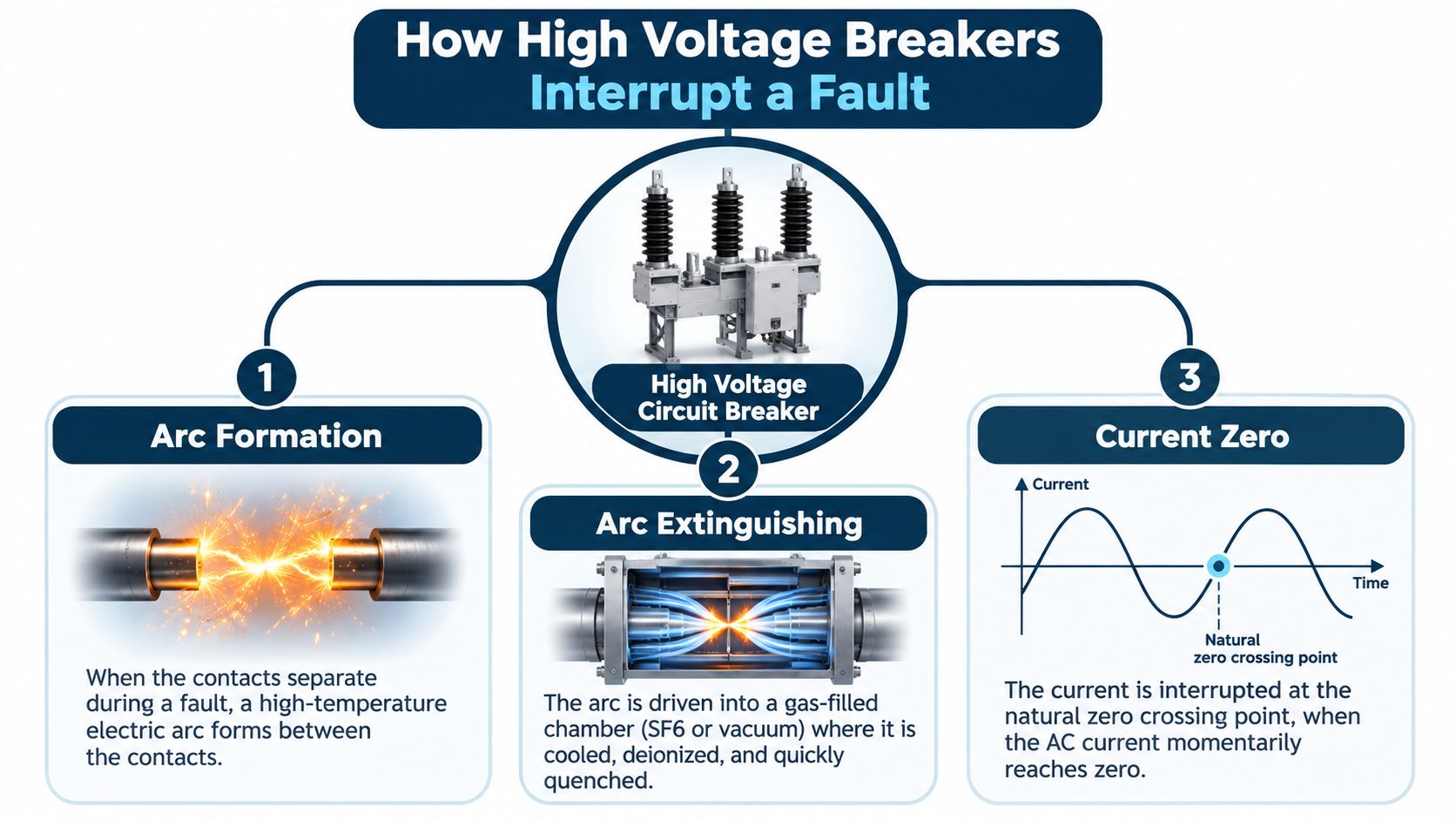
When a breaker opens under load or fault current, its contacts separate while current is still flowing. The gap doesn't immediately become an insulating space. The electrical field can ionize the material between the contacts and create an arc, a hot, conductive path that keeps current moving.
Think of the arc as a temporary bridge across a widening gap. The breaker must break that bridge, not merely pull the contacts apart. Every interrupting technology solves the same physical problem, but each uses a different medium to cool the arc and restore insulation.
The interruption sequence
First, the operating mechanism separates the contacts quickly enough to create the required gap. Speed and consistent motion matter because the interrupter has to manage the energy released during the opening process.
Second, the interrupter cools and deionizes the arc path. Oil, compressed air, SF₆ gas, and vacuum do this in different ways. Oil and air-blast designs are important parts of breaker history; modern applications more commonly weigh gas and vacuum options against voltage class, system design, and maintenance capability.
Third, the breaker must withstand the recovery voltage that appears across its open contacts as current falls to zero. If the insulation between the contacts can't recover quickly enough, the arc can restrike. A successful interruption therefore depends on both arc extinction and the ability to hold off the voltage that follows.
The distinction matters in procurement. A breaker isn't suitable just because its contacts can part or its interrupting medium is familiar. Its complete design must handle the current and voltage duty expected at the installation point.
Different media, same physical challenge
A vacuum interrupter extinguishes the arc in a sealed vacuum chamber. That approach is widely suited to medium-voltage switching, including motor and drive feeders, where compact equipment and limited routine maintenance can be advantageous.
SF₆ breakers use the insulating and arc-quenching properties of sulfur hexafluoride. They became central to high-voltage and extra-high-voltage applications as voltage and fault-current requirements rose. CIGRE's technical account describes a progression from oil and air-blast equipment to SF₆ designs, including single-break units rated at 245 kV and 40 kA and later units reaching 420 kV and 550 kV at 63 kA (CIGRE's history of SF₆ in transmission and distribution networks).
Air-blast designs use compressed air to cool and interrupt the arc. They have served high-voltage and generator applications, but their operating and maintenance requirements differ from those of sealed vacuum or gas interrupters.
The shared mental model is straightforward: separate, quench, withstand. Selection depends on which technology can perform those jobs at the site's voltage and fault duty, and on whether the plant can support its maintenance needs over the breaker's service life.
Comparing SF6, Vacuum, and Air Breaker Technologies
No interrupting medium is the right answer for every breaker position. SF₆ suits high-voltage applications that demand compact, high-performance interruption, but owners must manage gas condition, leak monitoring, recovery, and end-of-life handling. Vacuum is often a strong fit for medium-voltage motor and drive feeders, where a compact interrupter and simpler routine maintenance are priorities. Air avoids a fluorinated-gas inventory, but the plant still needs to evaluate the equipment configuration, operating mechanism, and service requirements.
| Attribute | SF₆ | Vacuum | Air |
|---|---|---|---|
| Typical fit | High-voltage and extra-high-voltage switchgear | Medium-voltage feeders, motors, and drives | Selected outdoor high-voltage and generator applications |
| Footprint | Compact for its voltage capability | Compact in medium-voltage switchgear | Varies by design; may require more supporting equipment |
| Maintenance focus | Gas density, leakage, gas quality, mechanism condition | Contact wear, interrupter integrity, mechanism condition | Air system and mechanism condition, where applicable |
| Environmental consideration | Requires controlled gas handling and recovery | No SF₆ gas inventory in the interrupter | No SF₆ gas inventory, though equipment still has service needs |
What the comparison can't decide for you
A table can clarify broad differences, but it can't select the breaker for a specific bus. The actual decision depends on system voltage, fault level, switching duty, available space, climate, maintenance skills, and how the site will manage parts and service. A 145 kV retrofit, for example, shouldn't be evaluated only on purchase cost or footprint. Include gas handling and recovery arrangements in the lifecycle review if SF₆ is under consideration.
Vacuum's advantages also have limits. It's a practical choice for many MV applications, but don't assume it can replace a high-voltage gas breaker without checking the available product design and its certified ratings for the application. Likewise, air isn't automatically simpler just because it avoids gas. The plant must be able to inspect and maintain the specific operating and support systems the selected design requires.
Selection test: Choose the interrupter technology only after the system duty, maintenance capability, and end-of-life plan are clear.
For heavy-industry sites, the most important question is often which breaker belongs in which position. Vacuum may be well suited to a drive feeder; a gas-insulated design may suit a higher-voltage connection where compactness and interruption capability dominate. The best lineup can use different technologies at different levels, provided each device is rated and coordinated for its actual duty.
Ratings and Standards That Actually Matter
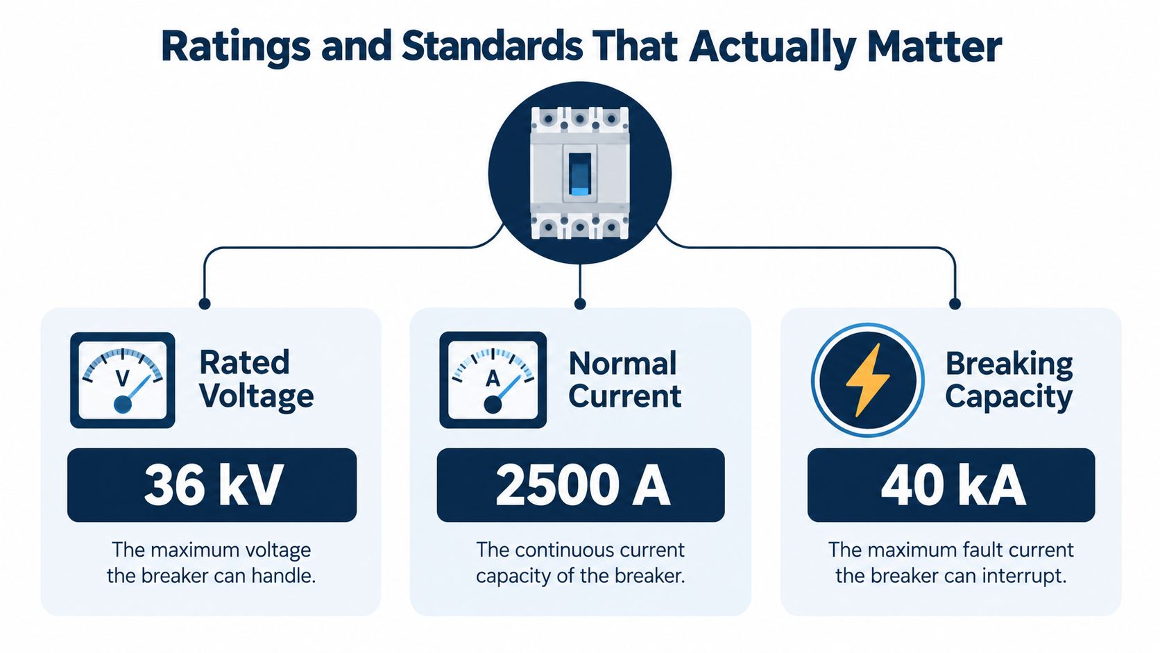
A breaker data sheet is useful only if the plant team understands what each rating governs. Rated voltage defines the system voltage class the breaker is designed to serve. Normal current describes the continuous current it can carry under specified conditions. Short-circuit breaking current states the fault current it can interrupt, while short-time withstand and making-current ratings address the stresses it must endure during a fault and when closing onto one.
Read ratings as a set
A breaker's continuous-current rating isn't its fault-interruption capability. A device can carry normal load current and still be unsuitable for the prospective short circuit at its installation point. Similarly, the making-current rating matters when the breaker closes onto an existing fault, because the first current peak can impose severe mechanical stress before the device opens.
Don't overlook the transient recovery voltage, or TRV, across the contacts after interruption. The breaker must recover insulation against the system's voltage transient, not only interrupt the stated current. A specification that names breaking current but omits the applicable system conditions and recovery-voltage duty can leave a critical selection gap.
Short-circuit data also needs context. The symmetrical current rating and the DC component of the fault affect the duty seen by the breaker. Ask the supplier to confirm that the proposed breaker's certified application covers the plant's calculated fault conditions, rather than relying on one headline number.
For system class and project specification, IEC 62271 is commonly used for high-voltage switchgear and breakers, while the IEEE C37 series is widely used in North American practice. Projects in China also need to align applicable GB and DL requirements with the project specification and local acceptance process. The procurement team should identify the governing standard and edition instead of assuming that ratings presented under different standards are interchangeable.
Let reliability evidence shape the maintenance plan
CIGRE reliability surveys covered 77,892 breaker-years of service from 102 utilities in 22 countries, and the findings helped establish the empirical basis for IEC testing requirements. The survey reported that major-failure frequency rises with voltage rating, while also recording significant reliability improvements over the preceding decades (CIGRE's reliability survey on equipment).
That history reinforces a field lesson: voltage rating alone doesn't tell you whether a breaker is fit for continued service. Operating duty, switching history, mechanism condition, insulation health, and the consequence of failure belong in the decision. When reviewing a broader switchgear lineup, keep the function of an insulated-case breaker distinct from that of the high-voltage device feeding the site.
Before approving a specification, confirm the system voltage, continuous current, fault duty, making and withstand requirements, TRV conditions, control supply, operating sequence, and coordination assumptions. If any of those are missing, ask for clarification before the purchase order is released.
Selecting and Coordinating Breakers with MV and HV Drives
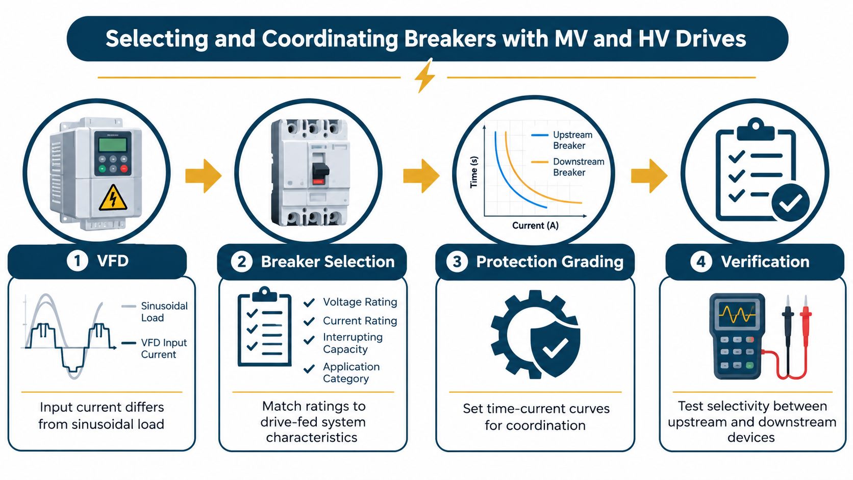
A VFD changes what a feeder breaker sees. Its input current isn't the smooth, sinusoidal current drawn by a conventional motor load. The drive's rectifier, DC-link components, input transformer, and system configuration affect the current waveform and the transient conditions during energization. Protection settings that ignore those characteristics can trip on normal events or fail to isolate a genuine fault selectively.
Start with the one-line and the fault study
Trace the supply from the incoming breaker through the transformer and MV bus to the drive feeder, input isolation device, and drive protection. Mark where each protective device should trip, and identify which device provides backup if the nearest breaker fails. Then verify the available fault current at each location against the breaker's interrupting and making duties.
Next, review energization and operating duty. Transformer inrush and drive capacitor charging can produce transient current that a generic trip curve may misread. The protection engineer should check the drive and transformer manufacturer's application requirements, then coordinate instantaneous, short-time, and ground-fault functions so the feeder clears local faults without unnecessary upstream trips.
A dedicated MV breaker ahead of a large drive can make sense when the drive's duty and protection needs differ from those of a general-purpose feeder. But adding a device doesn't guarantee selectivity. Its ratings and relay settings must fit the system study, and the upstream breaker must remain capable of backup protection.
Validate the assumptions before commissioning
Harmonic content can affect heating and electrical stress in connected equipment, so don't treat a drive feeder as an ordinary motor circuit without checking its design and loading. At the same time, don't assume that harmonics automatically reduce available short-circuit current or use that assumption to justify a lower breaker rating. Calculate fault duty from the system configuration and confirm it at the breaker location.
Before restart: Compare the trip record with the drive fault history and relay event data. Clear the initiating cause, confirm the intended protection boundary, and only then authorize a controlled restart.
A drive's own protection is not a substitute for feeder-breaker coordination. The drive can detect internal faults and protect its power electronics, while the breaker provides isolation at the electrical distribution level. Their roles should be explicit in the protection narrative and commissioning records.
For drive-specific application and service considerations, use the medium-voltage drive guide alongside the site's electrical study. During commissioning, test the trip path, verify interlocks and control power, and confirm selectivity using the approved settings. Record the final settings and the basis for them, so future maintenance teams can distinguish an intentional operating limit from an undocumented adjustment.
Maintenance and Condition Monitoring for HV Breakers
Time-based maintenance gives a site a predictable inspection routine. Condition-based maintenance adds evidence about the breaker's actual state. Neither replaces the other: use the manufacturer's maintenance requirements as the baseline, then let operating history and diagnostic results determine whether an earlier inspection or test is warranted.
The useful signals depend on the technology. For a vacuum breaker, trend contact resistance and operating-motion timing, and investigate changes in interrupter integrity or mechanism behavior. For an SF₆ breaker, monitor gas density and moisture alongside evidence of leakage. Across SF₆ and air-operated equipment, mechanism coil-current traces and travel curves can reveal sluggish or abnormal movement that a simple visual check may miss.
Turn a signal into an action
A sensor reading on its own isn't a maintenance decision. Compare it with the breaker's baseline, switching history, protection events, environmental contamination, and recent service records. Confirm data quality before escalating: inconsistent test setup or incomplete event records can make a normal variation look like degradation.
Use a practical action ladder:
- Inspect: Check the mechanism, connections, seals, controls, and contamination when an observation is abnormal but not yet supported by a critical defect.
- Test offline: Plan an outage when timing, resistance, insulation, or gas evidence needs confirmation with controlled testing.
- Derate or restrict operation: Consider this when a credible defect remains unresolved and the consequences of failure justify limiting exposure.
- Replace a subsystem or remove from service: Act when test results or operating evidence show that continued service can't be justified.
A single unusual signature shouldn't trigger replacement by itself, but it shouldn't be dismissed because the breaker still operates. Require a second line of evidence, a repeatable test, or a credible failure mechanism before choosing an intervention. Conversely, an abnormal result combined with a recent failed operation or protection event can justify prompt action.
For a plant with VFDs, link breaker records to drive alarms, feeder trips, transformer events, and maintenance work orders. That context makes it easier to decide whether the breaker or another part of the system caused a disturbance, and it gives the maintenance manager a clearer basis for scheduling the next outage.
End of Life Decisions and What to Do Next
A breaker nearing end of life may show repeated mechanism problems, deteriorating test results, hard-to-source spares, or gas-handling issues that are difficult to manage. Treat each signal as part of a wider condition assessment, not as an automatic instruction to replace the whole unit.
The options range from continued operation with tighter monitoring to interrupter refurbishment, a mechanism rebuild, subsystem replacement, or full changeout. Choose based on verified condition, parts support, fault duty, outage risk, and compatibility with the planned switchgear and drive lifecycle. A VFD retrofit can be a useful point to review the adjacent breaker and protection scheme, but it doesn't by itself prove the breaker needs replacement.
Set a decision meeting with electrical maintenance, protection engineering, operations, and procurement. Agree on the evidence required to keep the breaker in service, the trigger for intervention, and the outage window. That approach avoids both premature replacement and an unsupported late-life restart.
DUCHENG Industrial supports industrial VFD assets through commissioning, troubleshooting, maintenance, repair, and on-site reconditioning, including medium- and high-voltage drives. If a breaker trip has exposed questions about drive condition or restart readiness, contact DUCHENG Industrial to discuss a field-based assessment and a controlled recovery plan.