
Learn what an insulated case breaker is, how it works, key ratings and when to choose it over MCCB or power breakers for industrial plants.
A downstream motor fault has just taken out the plant's main breaker. The fault is local, but the outage isn't. Production stops, operators wait for clearance, and the maintenance team starts asking why an upstream device opened before the feeder breaker had a chance to isolate the problem.
That situation is rarely solved by choosing the breaker with the largest catalog rating. In an industrial plant, the better question is whether the protection system can carry the load, withstand the available fault, coordinate with downstream devices, and remain serviceable across its working life. An insulated case circuit breaker, or ICCB, often fits that need, but it isn't automatically interchangeable with every molded-case circuit breaker or low-voltage power breaker.
This guide builds the subject from the inside out. You'll learn what an insulated case breaker is, how its stored-energy mechanism operates, which ratings matter, where it fits against other breaker classes, and how to make a defensible choice in a mixed-vendor plant.
Table of Contents
- Introduction to Insulated Case Breakers in Industrial Power Systems
- What an Insulated Case Breaker Is and Where It Fits
- How Insulated Case Breakers Work Inside
- Key Specifications and Ratings You Must Understand
- Insulated Case Breaker Versus MCCB and Power Breaker Applications
- Selection Installation and Maintenance for Reliable Plant Operation
- Choosing the Right Protection Strategy for Your Facility
Introduction to Insulated Case Breakers in Industrial Power Systems
A downstream motor fault does not have to shut down an entire plant. The feeder breaker should normally open first, leaving the main breaker closed. If the feeder cannot clear the fault, or the fault is severe enough, the upstream device then isolates the affected portion of the system.
This sequence is selective coordination. It works like a row of protective gates: the gate closest to the fault should close first, while the others stay open. Without that separation, a short circuit in one machine area can trip the main breaker and interrupt unrelated production, controls, ventilation, and auxiliary systems.
ICCB selection matters when continuous current is high, fault levels are substantial, or the protection system needs controlled timing between upstream and downstream devices. An insulated case circuit breaker often occupies the space between a conventional molded-case application and a large power circuit breaker. It may suit low-voltage distribution where higher interrupting capability, adjustable protection, or service access is needed, without requiring the full construction of a power breaker lineup.
The insulated case breaker category emerged in the mid-1960s as a distinct class for higher-current service and has retained that role in industrial distribution. Early product documentation described the original design as the first insulated case circuit breaker design in the historical breaker documentation.
The practical decision goes beyond “ICCB or MCCB?” In a mixed-vendor plant, the maintenance manager should ask:
- Will the breaker interrupt the available fault current?
- Can its time delay allow the downstream breaker to operate first?
- Can technicians inspect, test, and replace it within the plant's outage limits?
- Will the unit fit the existing bus, cell, controls, and documentation?
- Can trip-unit support and spare parts remain available through the equipment lifecycle?
An ICCB may be interchangeable with an MCCB for a particular duty when ratings, physical fit, coordination, and service support all match. It is not interchangeable just because both devices protect low-voltage circuits. Those checks become especially important in steel, tire, chemical, and utility facilities where different equipment generations share one distribution network.
What an Insulated Case Breaker Is and Where It Fits
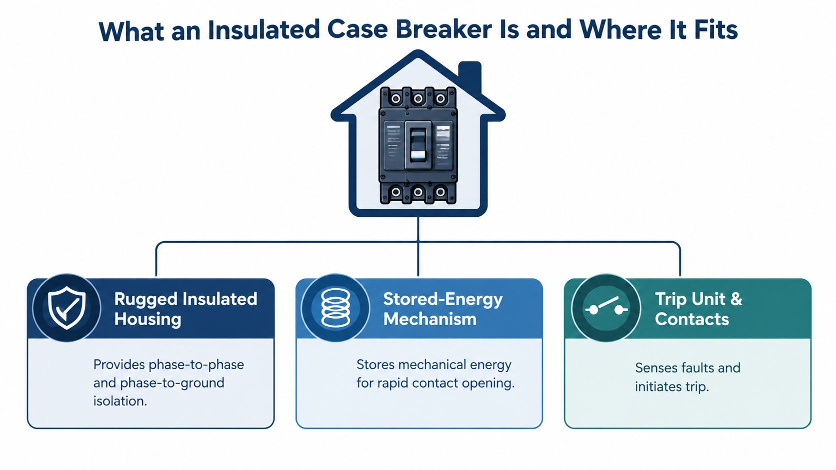
In a mixed-vendor plant, a breaker can have the right ampere rating and still be the wrong replacement. The installation may require a particular interrupting rating, time-current behavior, mounting arrangement, control voltage, and source of spare parts. An insulated case breaker is therefore best understood as part of a protection system, not as a larger version of an MCCB.
An ICCB is a rugged low-voltage breaker assembly inside an insulating housing. The housing separates and supports the current-carrying and interrupting parts. A stored-energy operating mechanism moves the contacts with controlled mechanical force, allowing repeatable operation during normal switching and fault clearing. IEEE Std 1015 uses this combination of insulated construction and stored-energy operation to define the class. The related terminology appears in the IEEE low-voltage circuit-breaker guidance.
The position between breaker classes
An MCCB commonly protects branch circuits, subfeeders, smaller motors, and general distribution equipment. Its molded case and trip options can provide effective overcurrent protection, but its construction, accessories, and service method vary across frame sizes and product families.
An ICCB uses an insulated case while targeting higher current, higher interrupting duty, more demanding mechanical operation, and more deliberate coordination. Historical reference material places common ICCB service roughly in the 800 A to 5000 A range, as shown in the insulated breaker reference material. Treat that range as orientation only. The selected frame, trip unit, interrupting rating, and tested configuration must come from the applicable equipment data.
A low-voltage power circuit breaker usually belongs in a larger switchgear assembly, often with drawout construction, extensive accessories, and defined main or critical-feeder duties. Catalog terminology can overlap, so the tested assembly and replacement interface matter more than the product label.
Why the classification matters
The ICCB class emerged in the mid-1960s for higher-current service. It is covered under UL 489, which also addresses molded-case circuit breakers and molded-case switches. The relationship between low-voltage power distribution and switchgear standards is summarized in the standards comparison bulletin.
For plant decisions, an ICCB can replace an MCCB only when the electrical ratings, selective coordination, physical fit, controls, and service support all match. Shared low-voltage duty alone does not make them interchangeable. In steel, tire, chemical, and utility facilities, that check protects both outage planning and long-term maintenance across equipment from different generations.
How Insulated Case Breakers Work Inside
A production line develops a fault at the worst possible moment. The ICCB must recognize the abnormal current, release its stored operating energy, separate the contacts, and contain the resulting arc before the fault spreads through the distribution system. That sequence happens automatically, without waiting for an operator to reach the switchboard.
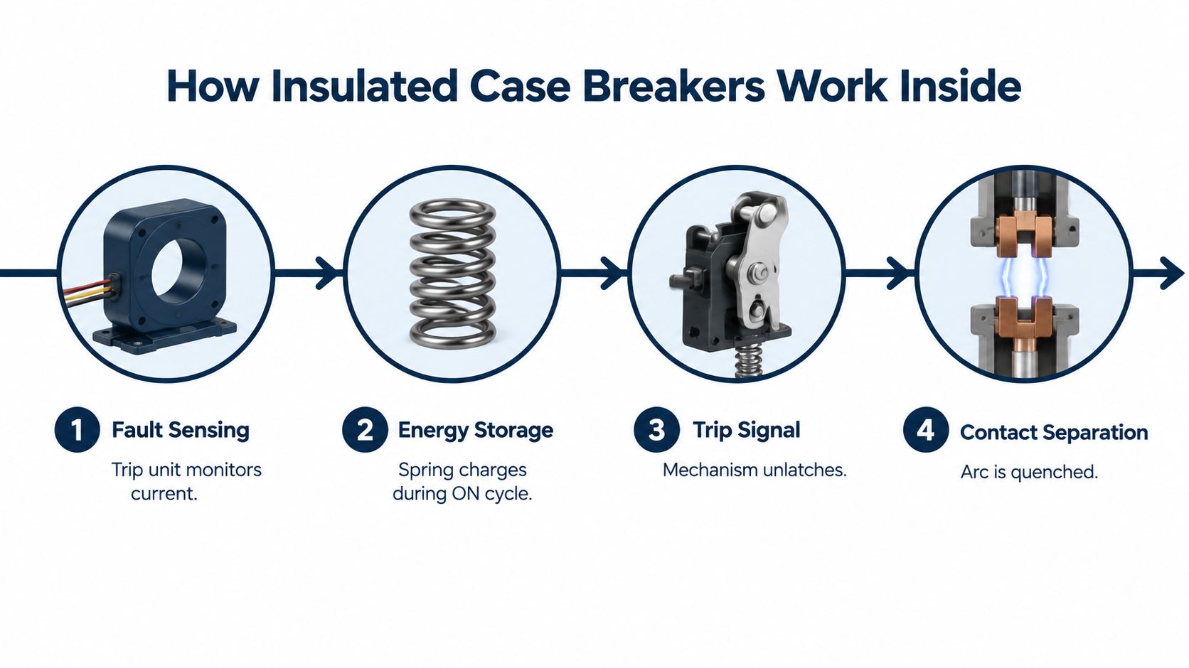
From abnormal current to an open circuit
First, the trip unit senses the condition. Depending on its configuration, the trip system evaluates overload, short circuit, ground fault, and other programmed conditions. It compares the measured current with the protection settings, much like a plant operator comparing a process reading with its alarm limit.
Second, the mechanism releases stored energy. The operating spring, or another stored-energy arrangement, supplies the force needed to unlatch and move the contacts. The breaker therefore responds through a prepared mechanical action rather than relying on slow manual movement during a fault.
Third, the contacts separate. Opening the metal contacts does not stop current instantly. An electrical arc forms across the growing gap, so the breaker uses its internal geometry and arc-control components to stretch, cool, and interrupt that arc.
Finally, the insulated housing and interrupting structure contain the event. The enclosure must withstand the electrical and mechanical forces created by the fault. Afterward, the breaker must reach a condition suitable for inspection, reset, or replacement under the equipment design and site procedure.
Practical rule: The trip setting indicates when the breaker should act. The interrupting and withstand ratings indicate whether it can survive the fault duty.
Why short-time withstand supports selectivity
Selective coordination may require an upstream breaker to remain closed briefly while a downstream device clears the fault. That delay works only when the upstream ICCB has the required short-time withstand capability, and when the complete protection scheme has been studied against the actual system fault levels and time-current relationships.
Commercial ICCB ranges can include interruption ratings up to 150 kA, with short-time withstand capability available for selectivity in suitable configurations, as described in the IEEE breaker guidance. The applicable rating still depends on voltage, frame, trip unit, accessories, and the tested combination.
A mixed-vendor plant needs more than a high current rating. The engineer must verify the available fault duty, the intended clearing sequence, and coordination between upstream and downstream devices. An ICCB may be physically suitable as an MCCB replacement yet still be a poor choice if its trip characteristics create nuisance operation or defeat selectivity. Service records, compatible accessories, and future testing also affect whether that replacement remains maintainable.
The internal design supports higher interrupting duty and mechanical endurance than many typical MCCB applications. That difference matters where the breaker switches repeatedly, controls fault energy, or protects a distribution section whose main trip would interrupt a large part of production.
<iframe width="100%" style="aspect-ratio: 16 / 9;" src="https://www.youtube.com/embed/tNK07U6Id-8" frameborder="0" allow="autoplay; encrypted-media" allowfullscreen></iframe>Key Specifications and Ratings You Must Understand
A breaker schedule can look precise while still hiding decisions that affect plant uptime. Read each rating as an operating question. In a mixed-vendor plant, the suitable device is the one that meets the electrical duty, coordinates with neighboring breakers, and can be serviced with the available parts and test equipment.
The ratings that establish suitability
Continuous current and frame size show whether the breaker can carry the expected load without becoming the weak point in the distribution path. Published technical guidance describes ICCB service in the broad range of 800 A to 5000 A, although frame and continuous-current combinations vary. Check the exact assembly, ambient conditions, conductor arrangement, and future loading against the historical ICCB reference.
Interrupting capacity shows whether the breaker can safely open the available short-circuit current at the stated voltage. Published vendor guidance includes examples rated up to 200,000 A symmetrical interrupting capacity at 240 V, while other product families reach 6000 A with interruption capability up to 100 kA at 635 Vac. These values belong to specific tested configurations. Use the technical guide for high-current breaker ratings rather than transferring a rating from one family to another.
Short-time withstand indicates whether an upstream breaker can remain closed during the coordination interval. That capability supports selective coordination when a downstream feeder should clear the fault before the main opens. It is useful only when the study, trip settings, and tested breaker arrangement support the intended sequence.
Voltage rating must match the system voltage and the fault duty at that voltage. Interrupting capacity often changes as voltage changes, so current and voltage ratings must be reviewed together.
Trip-unit functions determine whether the breaker can carry out the protection strategy. Long-time, short-time, instantaneous, and ground-fault functions are commonly grouped as LSIG. The available settings, sensor range, accessories, and communications options still need to match the coordination study and protection philosophy.
A practical reading table
| Rating | Typical ICCB Range | Why It Matters for Plants |
|---|---|---|
| Continuous current | 800 A to 5000 A in a commonly described range | Confirms that the breaker can carry the expected load and support the selected frame |
| Interrupting capacity | Up to 150 kA in published commercial ranges | Confirms that the device can interrupt available fault current at the stated voltage |
| Symmetrical interrupting capacity | Up to 200,000 A at 240 V in specific listed configurations | Helps evaluate severe fault duty, but only for the tested breaker arrangement |
| Higher-current product family example | Up to 6000 A and 100 kA at 635 Vac in some families | Shows why voltage, frame, and configuration must be reviewed together |
| Short-time withstand | Available in selectivity-oriented configurations | Allows the upstream device to ride through the coordination interval when the study supports it |
The table gives useful screening points, not permission to substitute one breaker for another. An ICCB may fit the same current range as an MCCB, yet its trip behavior, mounting, accessories, and tested combination may differ. In a mixed-vendor plant, interchangeability depends on the complete protection and maintenance arrangement, not the nameplate current alone.
The features that affect maintenance
Trip units may provide metering, alarms, communications, and event information. These functions help technicians identify loading and trip conditions instead of treating the breaker as a black box. Their value depends on maintained sensors, verified settings, usable records, and a clear response to alarms.
Construction affects the maintenance workflow. A fixed breaker can suit an installation where planned isolation is acceptable. A drawout breaker can support controlled inspection and replacement, provided the switchgear cell, racking mechanism, shutters, secondary connections, and interlocks are compatible.
North American standardization developed through milestones including the incorporation of ANSI C37 into UL 1558 and UL 1066, as documented in the earlier standards reference. The engineer still needs the current listing, tested assembly information, and installation requirements for the exact equipment. Service records and future test access should receive the same attention as the initial rating review.
Insulated Case Breaker Versus MCCB and Power Breaker Applications
A feeder trips during a plant upset, and the replacement breaker fits the cabinet but disrupts coordination with upstream and downstream devices. That situation shows why MCCB, ICCB, and low-voltage power breaker selection cannot rely on frame size or ampere rating alone. Each class may serve a similar current range, yet its interruption duty, short-time behavior, mounting, accessories, and service method can differ.
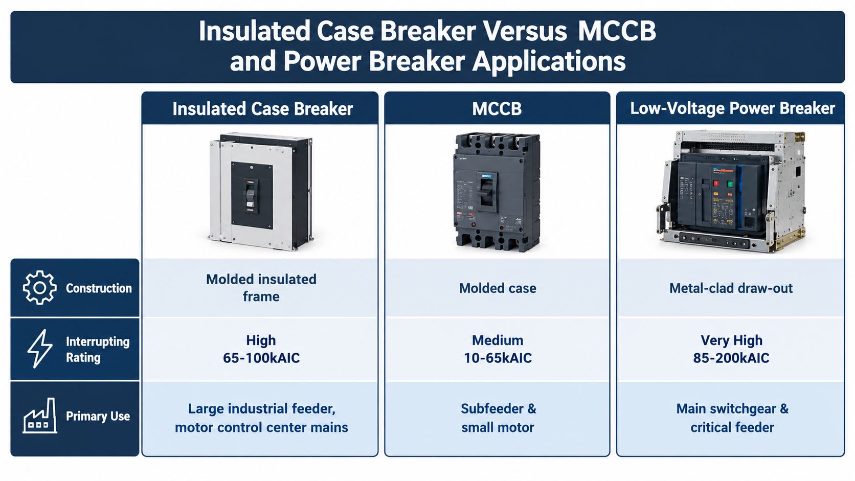
Compare the role, not just the frame
An MCCB often suits subfeeders, smaller motors, branch distribution, and installations where fault duty and coordination requirements fit the device. It may be fixed, compact, and economical to replace. Its short-time functions, accessories, and maintenance arrangements depend on the specific design.
An ICCB suits higher-current distribution when the plant needs an insulated case, stored-energy operation, greater fault capability, or more deliberate selective coordination. Published vendor guidance includes ICCB examples with continuous current ratings from 800 A to 4000 A, with some product families reaching 6000 A. These figures describe particular product families, not a universal ICCB specification. The published technical guide provides examples of that range.
A low-voltage power breaker generally fits main switchgear and critical feeder applications where drawout service, extensive accessories, compartmentalization, and high interrupting duty justify a larger assembly. It can offer a stronger service arrangement, while requiring more space, engineering, and compatible infrastructure.
When an ICCB can replace an MCCB
An ICCB may replace an MCCB when both devices provide the required system voltage, continuous load capacity, interrupting rating, connection arrangement, enclosure fit, protection settings, and applicable listing. Selective coordination must also remain acceptable across the full protection system. The review should include physical clearances, terminal orientation, control voltage, auxiliary contacts, shunt functions, interlocks, and maintenance access.
The term “insulated case” does not establish interchangeability. Two breakers with similar current ratings can respond differently during a fault because their trip logic, short-time withstand, mounting geometry, and tested combinations differ.
When it can't
Replacement becomes unsafe or impractical when the proposed ICCB does not fit the tested switchboard arrangement, meet available fault duty, or reproduce the original coordination behavior. A compact MCCB may carry the normal load yet lack the short-time withstand, drawout interface, or accessory system required by the plant.
| Application question | MCCB | ICCB | Low-voltage power breaker |
|---|---|---|---|
| Smaller feeder or branch protection | Often appropriate | Usually more capability than needed | Usually excessive |
| High-current feeder | Depends on frame and fault duty | Common application | Suitable where switchgear features justify it |
| Selective coordination | Depends on available functions and study | Strong candidate when short-time withstand is available | Strong candidate in engineered switchgear |
| Fixed installation | Common | Available in suitable configurations | Less typical for critical main arrangements |
| Drawout maintenance | Configuration-dependent | Available in selected designs | Commonly associated with the class |
| Mixed-vendor retrofit | Must verify exact interface | Must verify exact interface | Must verify cell, racking, and controls |
The market context explains why ICCB decisions receive attention. A 2022 industry market estimate placed the insulated case breaker market at USD 715 million, indicating continued commercial importance in industrial and utility power systems. The market and standards reference records that estimate. Market size does not replace engineering verification. In a mixed-vendor plant, the practical test is whether the breaker preserves selective coordination and can be serviced with the plant's existing cells, controls, spares, and procedures.
Selection Installation and Maintenance for Reliable Plant Operation
During a plant shutdown, a replacement breaker can fit the compartment and still fail the protection plan. Selective coordination, control compatibility, and future service access must be checked together. Treat the insulated case breaker as part of the protection and maintenance system, not as an isolated purchase.
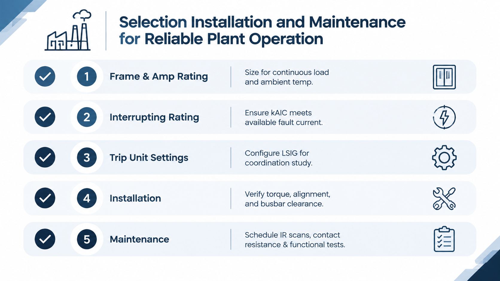
A field-ready workflow
-
Confirm the frame and ampere rating. Size the breaker for continuous load, ambient temperature, conductor conditions, and credible expansion. An existing nameplate is a reference, not a complete selection basis. Check the trip-unit range against the actual operating profile.
-
Verify fault duty. Obtain the available short-circuit current at the installation point and compare it with the breaker's interrupting rating at system voltage. Published examples include ICCBs rated up to 200,000 A symmetrical at 240 V. That value applies only to the listed configuration, so confirm the exact frame, trip unit, voltage, and installation conditions in the technical rating guide.
-
Set protection from the coordination study. Review upstream and downstream devices before configuring long-time, short-time, instantaneous, and ground-fault functions. Short-time delay may preserve selectivity, but the setting must remain within the breaker's withstand capability and the study's permitted clearing window. An ICCB may cover a duty that an MCCB can also cover, yet it is not automatically interchangeable if coordination functions, controls, or service arrangements differ.
-
Inspect the installation interface. Verify alignment, busbar clearance, terminal preparation, torque values, control wiring, secondary plugs, shutters, interlocks, and racking travel. Physical fit proves only one part of compatibility. A failed interlock or secondary-circuit test prevents commissioning.
-
Build the maintenance plan before energization. Record model data, settings, test results, spare-part references, and inspection intervals. Plan thermal inspection, contact-resistance checks, functional operation, trip testing, cleaning, and documentation review according to equipment condition and site risk.
Mixed-vendor serviceability
Legacy plants often contain breakers with different control voltages, connection arrangements, and drawing quality. Before dispatch, confirm the exact breaker, trip unit, accessory package, and connection kit. Check whether the replacement preserves selective coordination and whether technicians can isolate, test, repair, and return it to service using existing procedures and spares.
During shutdowns, inspect for contamination, heat damage, loose connections, mechanical wear, insulation deterioration, and repeated nuisance operation. Large breakers and associated equipment may be difficult to ship, so on-site testing and reconditioning can reduce handling risk and simplify outage planning. An industrial electrical maintenance service can support inspection, testing, and documentation.
Digital trip units and connected monitoring can show loading, events, and equipment condition. The benefit depends on alarm ownership, preserved settings, technician training, and a defined maintenance response.
Maintenance perspective: The most serviceable breaker is the one your team can identify, isolate, test, repair, and return to operation with documented confidence.
Choosing the Right Protection Strategy for Your Facility
A mixed-vendor plant can have two breakers with similar nameplates but very different behavior during a fault. Select the insulated case breaker when high continuous current, significant fault duty, and selective coordination must work together. An MCCB can serve when feeder duty, fault level, coordination, and maintenance practices fit that simpler class. Use a low-voltage power breaker when drawout service, advanced accessories, or switchgear integration justify the larger system.
For a retrofit, verify more than ratings. Check interrupting capacity, short-time withstand, trip-unit behavior, frame dimensions, bus and control interfaces, drawout hardware, spare-part availability, and enclosure condition. Vendor guidance includes ICCB examples with continuous current ratings from 800 A to 4000 A, with some product families reaching 6000 A. Similar current ratings do not make breakers interchangeable. The replacement must also preserve settings, connections, coordination, and a workable service procedure.
Lifecycle cost includes the service model, spare strategy, condition monitoring, and reconditioning path, not only the purchase price. The MCCB market outlook reports USD 1.36 billion in 2025 and projects USD 1.87 billion by 2030. These figures do not prove maintenance savings, but they support evaluating serviceability alongside equipment cost.
For commissioning, troubleshooting, retrofit planning, and asset care, use a documented electrical reliability service approach that connects protection settings with plant maintenance capability.
DUCHENG Industrial supports multi-brand commissioning, troubleshooting, preventive maintenance, spare-part reviews, and on-site reconditioning for industrial electrical assets. For an insulated case breaker retrofit or lifecycle plan, visit DUCHENG Industrial.