
Learn what a combination arc fault is, how to detect it, and essential safety tips for industrial environments.
At 2:15 on a humid production shift, a 480 V motor control center trips again. The conveyor stops, operators reset the bucket, and the drive accelerates normally, only for the same feeder to open later. A faint ozone smell hangs near a terminal block. The first theory is a failing overload relay. A closer inspection finds a loose ring lug, heat-darkened insulation, and early carbon tracking.
That situation is difficult because an industrial cabinet can produce many electrical signals that look abnormal without representing the same hazard. A variable frequency drive, switching power supply, or LED driver creates noise as part of normal operation. A deteriorating termination creates noise because current is forcing its way through a damaged contact. Combination arc fault protection must separate those conditions while still responding before a small defect becomes a sustained fire source.
The distinction matters beyond residential branch circuits. In a plant, the fault may develop inside an MCC bucket, VFD lineup, junction box, disconnect, or outdoor control enclosure. The right response combines detection logic with disciplined mechanical inspection, load compatibility review, and a documented retrofit plan.
Table of Contents
- When an Arc Fault Became a Plant Problem
- What a Combination Arc Fault Actually Is
- How Combination Arc Faults Start in Industrial Systems
- Standards and Detection Logic Behind Combination Arc Faults
- Why VFDs and Nonlinear Loads Change the Picture
- Detection Methods Compared for Industrial Use
- Mitigation Testing and Retrofit Strategies That Work
- Industrial Questions About Combination Arc Faults
When an Arc Fault Became a Plant Problem
The trip that looked like an overload
The maintenance team in this example had a familiar sequence. A conveyor feeder tripped intermittently, but motor current did not show a persistent overload. Operators reported no obvious loss of production capacity before each trip, so the initial assumption was that the overload relay or its settings had become unstable.
The cabinet inspection changed the diagnosis. Thermal imaging showed a localized hot spot at a ring-lug termination. After isolation and disassembly, technicians found that the connection had loosened enough to create a series arc. The heat had damaged nearby insulation, and carbonized material was beginning to create a second conductive path.
That is the practical meaning of a near-miss arc event. The first electrical symptom may be an intermittent trip, a smell of ozone, faint crackling, or discoloration that appears only after the cabinet has been operating under load. A standard thermal survey can also miss the earliest stage if the fault is intermittent, shielded by cabinet geometry, or active only during a particular drive speed or load transition.
Practical rule: Treat an unexplained intermittent trip as a possible wiring defect until the termination, conductor, insulation, and load waveform have been checked.
Why industrial cabinets complicate diagnosis
Residential AFCI guidance often focuses on protecting branch-circuit wiring, cord sets, and power-supply cords. In a plant, the same physical mechanisms occur alongside equipment that changes the electrical signature continuously. VFDs switch power electronically, motors create starting and regenerative behavior, and nonlinear loads distort current and voltage.
The maintenance challenge has two sides:
- Find the physical precursor: Loose lugs, cracked conductors, contamination, vibration, and damaged insulation can initiate the fault.
- Interpret the electrical evidence: The detection system must recognize dangerous arc behavior without confusing normal switching noise with an arc.
The historical reason for this protection is substantial. In the United States, arcing faults are estimated to cause more than 30,000 home fires each year, with hundreds of deaths and injuries and more than $750 million in annual property damage, according to the Electrical Safety Foundation International's AFCI information. Those figures describe homes, not industrial plants, but the underlying failure mode is the same: localized electrical energy heats combustible material without necessarily producing enough current to operate a conventional overcurrent device.
What a Combination Arc Fault Actually Is
Start with the plumbing analogy. A series arc is like a kink in a hose. The path is still part of the intended circuit, but a damaged connection restricts current through one conductor. The restriction produces heat and electrical noise, even when total current remains below the normal breaker threshold.
A parallel arc is like a leak between two hoses. Current jumps between phase conductors, between a conductor and ground, or across another unintended conductive path. The current can be much higher, so a conventional breaker may respond if the path becomes a solid short circuit. Early tracking, however, may remain too weak or intermittent for ordinary overcurrent protection.
A combination arc fault involves both behaviors in the same developing failure. One conductor or termination has already degraded, and the resulting heat, carbon, and insulation damage create a second path across conductors or to ground.
The three signatures maintenance teams should separate
A series arc often produces lower current, rapid interruptions, voltage disturbance, and broadband electrical noise. Its energy is concentrated at a damaged contact, such as a loose terminal, broken conductor strand, or poor crimp.
A parallel arc produces a different electrical relationship. The fault bridges two points that should remain electrically separated, so the current path changes across conductors or from conductor to ground. Its current can rise sharply, although contamination and carbon tracking may make the path unstable rather than fully conductive.
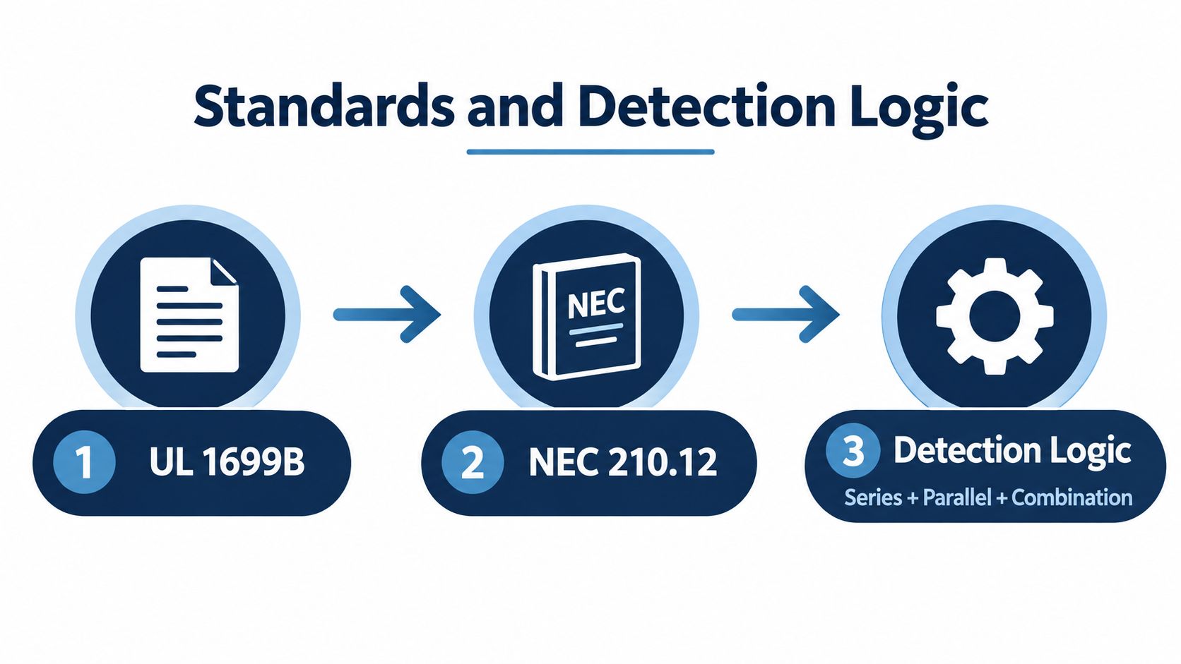
The word combination describes the required protection scope, not a special third wire arrangement. A combination-type device must detect both parallel arcing and lower-energy series arcing. Guidance based on UL 1699 describes low-current arc tests, including detection down to about 5 amperes in two-wire cords, which explains why combination devices cover conditions older branch/feeder designs could miss. See the IAEI explanation of combination AFCI testing for the technical distinction.
In an industrial cabinet, think of the fault as a progression. A loose connection begins as a hot restriction. The damaged insulation then becomes a carbonized surface. Moisture, dust, or vibration helps the conductive track extend until the fault includes a parallel component.
How Combination Arc Faults Start in Industrial Systems
The initiating event is often mechanical, not electronic. A lug that wasn't tightened correctly, a crimp that doesn't fully grip the conductor, or a terminal exposed to repeated vibration can create a small high-resistance region. Under load, that region heats and cools, and the conductor surface begins to deteriorate.
Plant conditions accelerate the process:
- Dust in MCCs: Fine conductive or semi-conductive deposits can settle on insulators and bus supports, especially where enclosure seals or ventilation paths allow contamination inside.
- Oil in compressor cabinets: Oil film attracts particles and can weaken insulation surfaces, creating a path for tracking between terminals.
- Humidity cycling in food processing: Condensation and drying cycles change surface conductivity and promote corrosion at connections and insulation interfaces.
- Vibration at motor feeders: Repeated movement can loosen terminations, fatigue conductor strands, and damage cable glands.
- Thermal cycling: Repeated expansion and contraction at bolted joints can reduce contact pressure over time.
From loose connection to carbon track
A series arc doesn't need a dramatic break in the conductor. A small gap, damaged strand, or unstable contact can interrupt and re-establish current repeatedly. Each interruption creates heat and electromagnetic noise at the fault location.
As insulation chars, the material's electrical behavior changes. The damaged surface can become a partial conductive bridge. If that bridge reaches another phase, a grounded enclosure, or a nearby terminal, the original series defect has developed a parallel leakage path. The fault now combines localized restriction with cross-path conduction.
VFD installations add another aging mechanism. Fast switching and cable-related voltage stress can challenge motor insulation and feeder components, particularly where cable selection, grounding, shielding, termination, or installation practices don't match the drive system. The VFD technical guide from DUCHENG Industrial provides useful context for understanding how drive operation differs from fixed-frequency motor supply.
A combination arc fault is often the electrical evidence of a mechanical defect that has been heating, moving, and degrading for some time.
The inspection priority should therefore follow the physical chain. Check terminations first, then insulation, contamination, cable entry points, bus joints, grounding paths, and the operating conditions present when the trip occurred. Replacing a breaker without finding the initiating defect can leave the cabinet on the same failure path.
Standards and Detection Logic Behind Combination Arc Faults
Arc-fault protection developed through successive changes to the NEC. The 1999 NEC introduced AFCIs, the 2002 edition extended them to all bedroom circuits in new homes, and the 2005 edition shifted the requirement toward combination devices. That requirement took effect on January 1, 2008, when AFCI breakers had to use the combination design instead of earlier branch/feeder designs, as documented by the National Association of Home Inspectors overview of AFCIs.
The engineering reason was greater sensitivity to lower-level series arcs. Earlier branch/feeder devices focused mainly on higher-current fault signatures. Combination devices extended protection to downstream branch wiring, cord sets, and power-supply cords. A commonly cited series-arc detection threshold is 5 amperes, compared with roughly 75 amperes peak for older branch/feeder detection. Those values come from the same AFCI history and technical explanation.
How the logic interprets an arc
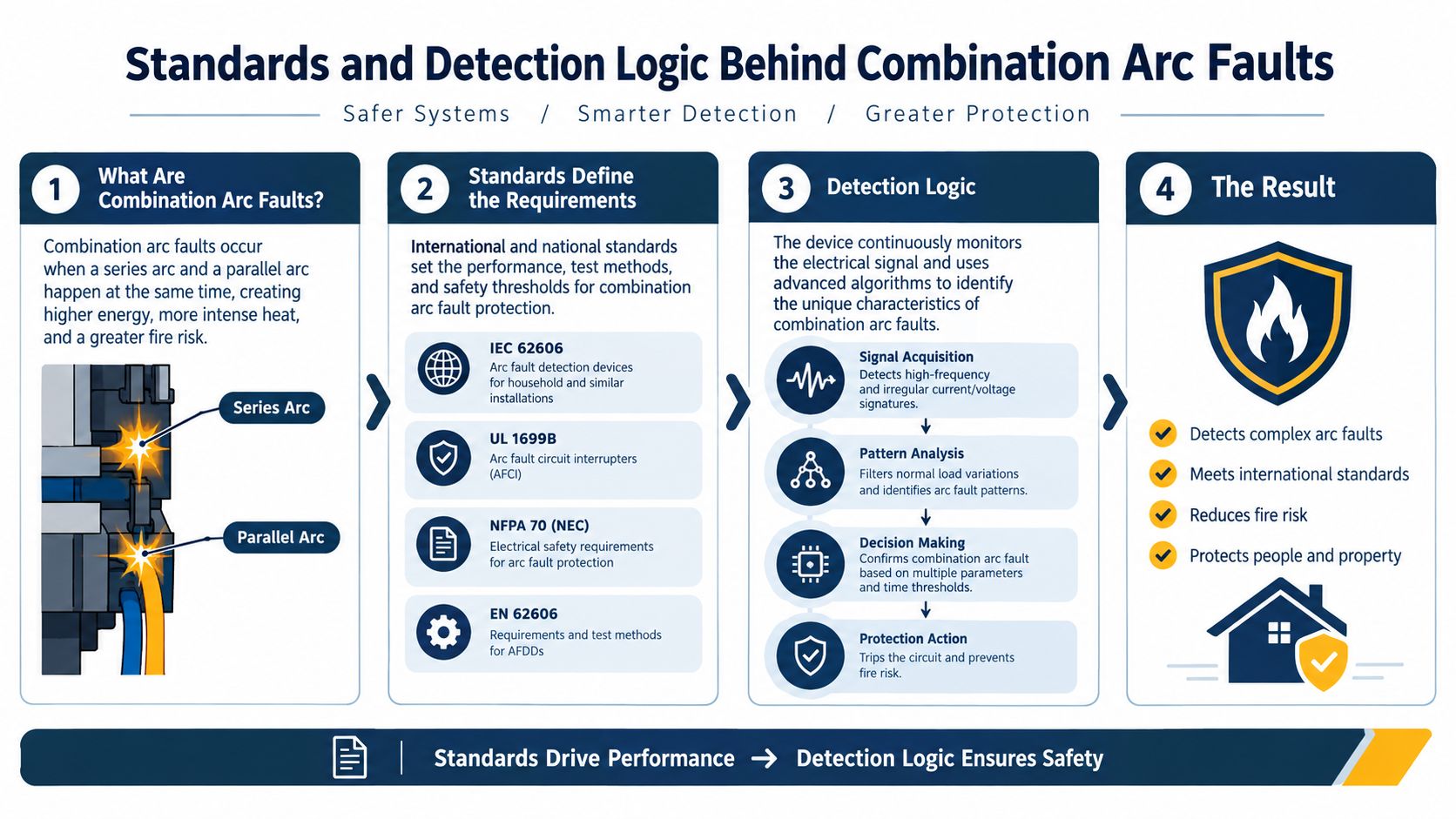
A combination device examines current behavior, and some arrangements also evaluate voltage. Its algorithms look for irregular conduction, repeated interruption, high-frequency components, and timing relationships between the waveform and the connected load.
No single signal proves that an arc is present. A VFD switching event can produce sharp current transitions. Motor starting can create inrush, while a power supply can draw nonsinusoidal current. Detection therefore combines multiple indicators with timing, repetition, and load-discrimination rules. The objective is to recognize an unstable fault pattern without treating every abnormal waveform as a failure.
The UL question corner explanation of system-combination AFCIs describes a protection arrangement that pairs a certified outlet AFCI at the first outlet with a specified molded-case breaker. For plant specifications, the practical lesson is to read the protection architecture, not just the word “combination” on a product label.
Why test terminology matters
Maintenance managers should confirm which fault conditions the device was evaluated to recognize, how nuisance-trip tests were performed, and whether the planned installation matches the certified arrangement. A workshop paper notes that system-combination types are not defined in UL 1699 and that no dedicated standard exists for that arrangement, even though it appears in NEC-era installations. The paper also discusses nuisance-trip testing across six load conditions, including inrush current, nonsinusoidal waveforms, crosstalk, multiple loads, and lamp burnout, in its technical discussion of arc-fault detection.
For an industrial retrofit, those categories become commissioning questions. Can the device remain stable during VFD acceleration? Can it separate crosstalk from a genuine fault? Does a mixed feeder behave differently when several loads switch together? Test reports should address those conditions before procurement approves the installation. UL 1699 test behavior provides a reference point, but cabinet wiring, load interaction, and operating sequence determine how that protection behaves in the plant.
Why VFDs and Nonlinear Loads Change the Picture
A VFD doesn't deliver a smooth, utility-frequency sine wave directly to the motor. Its switching devices build an output waveform from rapid voltage transitions. The motor and cable then respond to those transitions through capacitance, inductance, impedance, shielding, and grounding.
That normal behavior creates signals an arc detector must interpret carefully. Switched-mode power supplies and LED drivers also produce harmonic content and nonsinusoidal current. A fault detector that responds to more high-frequency noise will increase nuisance trips rather than improve plant safety.
The cable is part of the circuit behavior
A long motor lead can behave like a transmission line. Reflections at the motor terminals and impedance changes along the route can increase voltage stress, particularly where the cable, motor, and drive aren't matched as a system. Those repeated stresses can accelerate insulation aging, turning a waveform problem into a future physical arc source.
The drive's DC bus, switching devices, and load changes also inject common-mode currents. In a plant with multiple drives, control supplies, contactors, and communication wiring, crosstalk can add another layer of complexity. A detector must filter normal switching behavior without filtering out the irregular signature of a loose or carbonized connection.
| Load Type | Frequency Content | Typical Magnitude | Nuisance Trip Risk |
|---|---|---|---|
| VFD-fed motor | Switching components, harmonics, reflected-wave effects | Depends on drive state, cable, motor, and load | High if detection logic isn't matched to drive behavior |
| Switched-mode power supply | Harmonics and sharp input-current transitions | Depends on power demand and input design | Moderate to high in mixed control cabinets |
| LED driver | Switching noise and nonsinusoidal current | Depends on driver and connected lighting load | Variable, especially with many drivers together |
| Contactor or relay coil | Switching transient during opening and closing | Short-duration event | Usually controlled through timing and filtering |
| Resistive heater | Predominantly low-noise current waveform | Follows the heating demand | Lower, unless the connection is damaged |
Industrial detection must discriminate
A plant doesn't need a detector that reacts to every unusual waveform. It needs one that recognizes persistent, spatially meaningful, and fault-consistent behavior. That may require current sensors at feeder level, voltage references, event recording, and coordination with drive status signals.
The maintenance team should capture the operating state at each trip. Record drive speed, acceleration or deceleration, process load, cabinet temperature, recent work, and whether other loads switched at the same time. A trip that occurs only during a particular ramp may indicate compatibility or installation stress. A trip that follows cabinet vibration or high humidity may point more directly to a physical defect.
Detection Methods Compared for Industrial Use
No single method answers every plant's question. A breaker-based device can provide interruption, an intelligent relay can interpret site-specific behavior, and a portable analyzer can help locate an intermittent source before a permanent system is installed.
| Method | Detection Type | Strengths | Weaknesses | Best Cabinet Location |
|---|---|---|---|---|
| Combination AFCI device | Current-signature detection for series and parallel arcs | Provides protective interruption in the device architecture | May require careful compatibility review with nonlinear loads | Suitable branch or feeder applications where the device is certified for the system |
| AI-enhanced arc relay | Sensor data interpreted through learned or engineered load signatures | Can adapt analysis to complex operating conditions and record events | Requires commissioning data, validation, and dependable sensor installation | VFD lineups, process skids, and mixed-load distribution sections |
| Portable arc analyzer | Temporary electrical signature measurement | Useful during commissioning, audits, and fault reproduction | Doesn't provide permanent interruption by itself | MCC buckets, suspect feeders, and cabinets with intermittent trips |
| Thermal imaging | Surface temperature observation | Locates heat at loose or overloaded connections | Can miss intermittent or shielded faults | Accessible terminations, bus joints, and cable lugs |
| Partial-discharge survey | Insulation activity detection | Helps identify insulation deterioration before visible failure | Needs suitable access and interpretation | Medium-voltage compartments and stressed insulation systems |
| Ultrasonic inspection | Airborne or structure-borne sound from discharge | Can help locate audible high-frequency activity | Background plant noise can complicate results | Enclosures, disconnects, and accessible energized inspection points |
What conventional devices do well
A conventional combination AFCI device is most useful where the installation matches the device's certification and expected load environment. Its main value is direct protective action, not just event reporting. The specification should confirm voltage, current, system grounding, feeder arrangement, interrupting requirements, and compatibility with the connected equipment.
That last point deserves attention in VFD-heavy plants. A device designed around residential branch-circuit behavior may not be appropriate for an industrial feeder because its label includes “combination.” Engineers need to validate the complete protection arrangement and the expected waveform environment.
Where intelligent relays and analyzers fit
AI-enhanced detection is moving from rule-based analysis toward machine-learning and hybrid approaches, including CNN-Transformer models intended to identify arc signatures under complex load conditions, as discussed in this review of machine-learning arc-fault detection. The practical value isn't the label “AI.” It is the ability to test the model against actual cabinet noise, variable-speed operation, switching schedules, and known fault simulations.
A portable analyzer helps before that decision. Use it during commissioning or an outage to capture normal waveforms, reproduce nuisance trips under controlled conditions, and compare a suspect feeder with a healthy reference. Pair electrical data with thermal imaging, insulation testing, and visual inspection. For facilities also reviewing phase imbalance, rotation, or supply quality, a phase-monitor relay overview from DUCHENG Industrial can provide related context, but it doesn't replace arc-fault evaluation.
Mitigation Testing and Retrofit Strategies That Work
Detection works best when it sits inside a maintenance program. A device can interrupt a fault, but it can't tighten a loose lug, remove conductive dust, repair rodent damage, or correct a cable installation that is overstressing motor insulation.
Begin with a baseline risk audit during a planned shutdown. Document cabinet age, feeder type, load composition, environmental exposure, prior trips, recent modifications, and the condition of terminations. Then combine several inspection methods rather than relying on one instrument.
A practical shutdown sequence
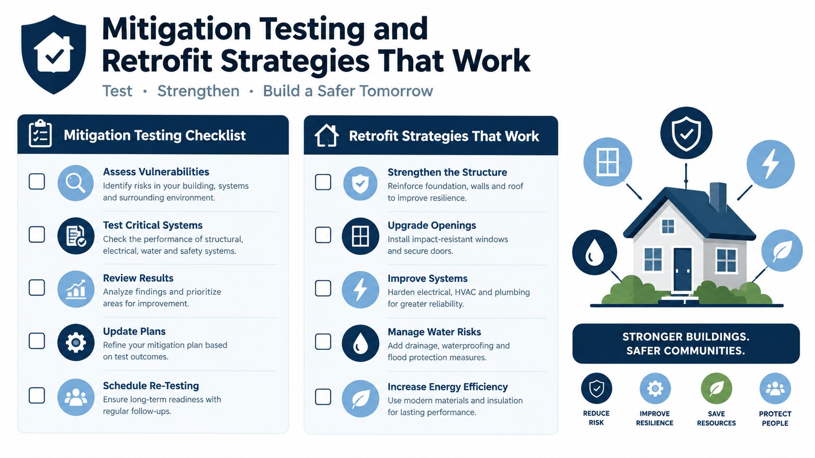
- Start with safe isolation. Verify zero energy before removing covers or disturbing conductors. Record the as-found condition before cleaning or reterminating anything.
- Inspect and restore mechanical integrity. Check lug condition, conductor insertion, crimp quality, bus joints, barriers, cable glands, grounding bonds, and signs of overheating. Apply the manufacturer's specified torque procedure.
- Trend insulation condition. Use insulation resistance testing where appropriate, and compare results with previous records rather than treating one reading as a complete diagnosis.
- Scan for hidden activity. Use thermography under representative load, partial-discharge methods where the equipment and voltage class support them, and ultrasonic inspection where access and background conditions allow.
- Capture normal electrical behavior. Record VFD ramping, steady-state operation, regenerative events, contactor switching, and simultaneous load changes. Those records establish the baseline for nuisance-trip analysis.
Maintenance principle: The first retrofit dollar should usually reduce the physical probability of an arc and the second should improve the system's ability to recognize what remains.
Choosing a retrofit architecture
Panel-mounted combination devices may suit smaller feeders or compatible branch-circuit arrangements. External arc relays using current and light sensing can fit switchgear where a separate trip circuit and zone coordination already exist. Zoned protection can help distinguish a fault in one compartment from a disturbance elsewhere, but it requires careful sensor placement, trip coordination, and testing.
A phased rollout limits risk:
- Pilot the highest-risk feeder: Choose a cabinet with repeated unexplained trips, visible degradation, heavy contamination, or sensitive process consequences.
- Test under real operating states: Include motor starts, VFD acceleration, load steps, switching events, and simultaneous operation of nonlinear loads.
- Document every trip: Save waveform data, cabinet photographs, operating state, and corrective action.
- Expand only after validation: Apply the approved architecture to similar buckets or lineups, then review whether the same settings remain appropriate.
Permanent detection should be tested with the equipment manufacturer's procedure and suitable test equipment. The record should show device identity, circuit location, test conditions, result, reset behavior, and any follow-up inspection. Repeat the physical checks quarterly or at the plant's established maintenance interval, with extra attention after cabinet work, flooding, contamination events, or unexplained trips.
<iframe width="100%" style="aspect-ratio: 16 / 9;" src="https://www.youtube.com/embed/iRLxHbgG_SA" frameborder="0" allow="autoplay; encrypted-media" allowfullscreen></iframe>Industrial Questions About Combination Arc Faults
How often should combination arc-fault devices be tested?
The correct interval depends on the device instructions, site safety program, operating environment, and applicable inspection requirements. A documented test isn't just pressing a button and writing “pass.” It should identify the device and circuit, record the date and person responsible, describe the test method, confirm the expected trip or alarm, and note whether the equipment reset correctly.
Add a physical inspection to the electrical test. Look for discoloration, dust, oil, moisture, damaged wire markers, loose hardware, and changes since the previous inspection. Repeated trips should trigger troubleshooting, not repeated resets.
Can protection be installed on an existing 480 V VFD feeder?
It may be possible, but compatibility must be demonstrated rather than assumed. Review the device voltage and current ratings, system grounding, interrupting capability, feeder arrangement, drive input behavior, motor-circuit configuration, and coordination with upstream protection.
Test the proposed arrangement during a controlled outage or commissioning window. Include VFD ramp-up, ramp-down, load changes, bypass operation if present, and nearby switching. If the device trips during normal operation, investigate waveform compatibility and the physical installation before changing settings or bypassing protection.
What should procurement budget for a retrofit?
Avoid quoting a generic cost range without a defined architecture. A low-voltage MCC retrofit may require sensors, a relay or compatible breaker, control wiring, testing, documentation, outage labor, and coordination review. A medium-voltage lineup may also require specialized access, insulation assessment, relay integration, and a more involved outage plan.
Procurement should request a complete bill of materials and scope of work. Separate equipment cost from engineering, installation, testing, commissioning, and corrective mechanical work. The least expensive detector can become the most expensive choice if it creates nuisance trips or fails to identify the physical source.
Does arc-fault protection replace arc-flash analysis or PPE decisions?
No. Arc-fault detection and arc-flash analysis address related but different questions. Arc-fault protection seeks to identify an unintended arcing condition and interrupt or alarm on it. Arc-flash analysis evaluates incident energy, equipment boundaries, clearing behavior, labels, work practices, and PPE requirements.
A combination arc-fault device may reduce the duration of a developing event in its protected zone, but that assumption must be supported by the actual protection scheme and coordination study. Keep arc-flash labels and energized-work procedures aligned with the installed equipment, and use the applicable electrical safety program for inspection and maintenance decisions.
The product frontier is also changing. Recent reference-design work positions machine-learning and AI-based detection with current sensors for applications including solar systems, energy storage, EV chargers, smart ignition systems, electronic fuses, and residential and industrial safety switches. For plant managers, the useful evaluation criteria remain practical: performance in noisy cabinets, behavior around VFDs, false-positive control, retrofit feasibility, event recording, and maintainability.
A combination arc fault is rarely just a breaker problem. It is usually a developing interaction between a degraded connection, an aging insulation system, contamination, mechanical stress, and a detection system that must interpret a difficult waveform. During the next outage, select one high-risk feeder, document its physical condition, capture its normal electrical behavior, and validate any protection change before expanding it across the plant.
DUCHENG Industrial supports industrial VFD commissioning, troubleshooting, preventive care, repair, and on-site reconditioning, with work that can help maintenance teams investigate drive-related trips and cabinet aging alongside arc-fault mitigation. Visit DUCHENG Industrial to discuss a planned inspection, controlled restart, or lifecycle service requirement for your drive systems.