
Learn what phase monitor relays do, how they detect phase loss and asymmetry, wiring tips, and when to use them with VFDs.
A pump is running normally at the start of a shift. After a utility disturbance or a blown feeder fuse, one phase falls low while the other two remain present. The starter still appears available, the control circuit still has power, and the motor may even produce enough torque to keep turning. By the time someone notices the abnormal sound or rising temperature, the motor has already been operating under a damaging electrical condition.
That failure is why phase monitor relays deserve attention beyond the motor starter itself. These devices watch the three-phase supply and can prevent a start, open a control circuit, or signal a PLC when the feeder no longer meets defined electrical conditions. They're not a replacement for overload protection, and they aren't automatically required beside every variable frequency drive. Their value depends on where the electrical risk exists and how the protection architecture is arranged.
Table of Contents
- Why a Missing Phase Can Stop Your Plant
- What Phase Monitor Relays Do and How They Work
- Core Protection Functions Every Relay Should Cover
- Wiring Diagrams and Setting Up Thresholds Correctly
- Selecting the Right Relay and Integrating With VFD Systems
- Troubleshooting Nuisance Tripping and Commissioning Tips
- Making Phase Monitoring Part of Your Protection Strategy
Why a Missing Phase Can Stop Your Plant
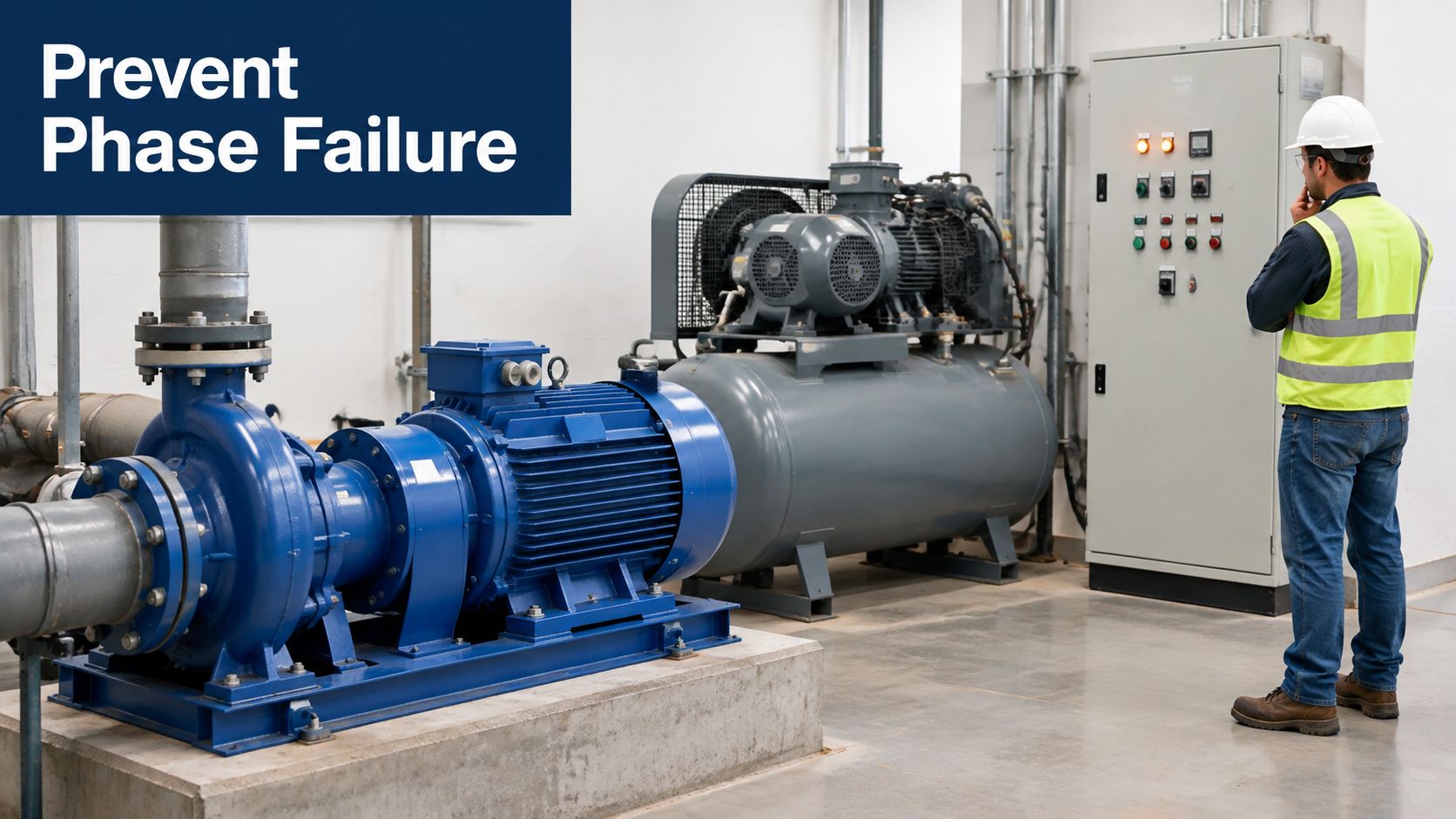
A pump is running during a normal shift when a feeder fuse opens, a terminal loosens, or an upstream connection loses continuity. The motor may not stop at once. An induction motor can continue turning through abnormal electrical conditions, so the operator may see a running pump or compressor instead of an obvious trip.
The risk sits in the feeder, not only inside the motor. An incomplete or badly unbalanced voltage supply can produce abnormal current, overheating, difficult acceleration, or a failed start. If two incoming phases are interchanged during maintenance, the motor can rotate in the wrong direction. A pump may run backward, a compressor may unload incorrectly, or a conveyor may travel the wrong way before anyone reaches the disconnect.
Phase monitor relays provide a control-level response to these conditions. They measure the incoming three-phase supply, compare it with configured limits, and change an output contact when the feeder is no longer acceptable. Their protection role is described in equipment documentation aligned with IEC/EN 60947-1 and IEC/EN 60947-4-1, including the Lovato phase protection relay documentation.
Questions maintenance teams need answered
A sound installation decision starts with the feeder architecture. Ask:
- Which faults matter: Is the circuit exposed to phase loss, sequence reversal, undervoltage, overvoltage, or voltage unbalance?
- Where should protection sit: Should the relay supervise the motor branch, the feeder, a bypass circuit, or the input to a variable frequency drive?
- How quickly should it act: Should a missing phase open the control circuit immediately, or should the relay tolerate a short voltage sag during a large motor start?
- What should happen after a fault: Should its output block a contactor, disable a drive, alarm the PLC, or perform more than one of these actions?
- Which risks are already covered: A VFD can detect some input faults internally, but that protection may not supervise upstream contactors or other loads sharing the feeder.
Treat the relay as a feeder guardian, rather than an automatic accessory for every motor. Its value depends on where the fault can occur, which device already detects it, and what safety logic must respond. For a standalone motor branch, the relay may add direct control over the contactor circuit. Beside a VFD, it may duplicate internal monitoring unless the plant also needs upstream isolation, feeder-level alarming, or protection for equipment outside the drive. The following sections examine those choices through relay operation, voltage conditions, wiring, settings, commissioning, and nuisance-trip diagnosis.
What Phase Monitor Relays Do and How They Work
A motor can stop without its overload relay ever seeing a simple overcurrent. A fuse may open on one phase, a conductor may loosen, or a disconnect contact may fail. The motor might still turn, but its three-phase magnetic field is no longer balanced. That is why a phase monitor relay belongs in the feeder protection discussion, not automatically beside every motor.
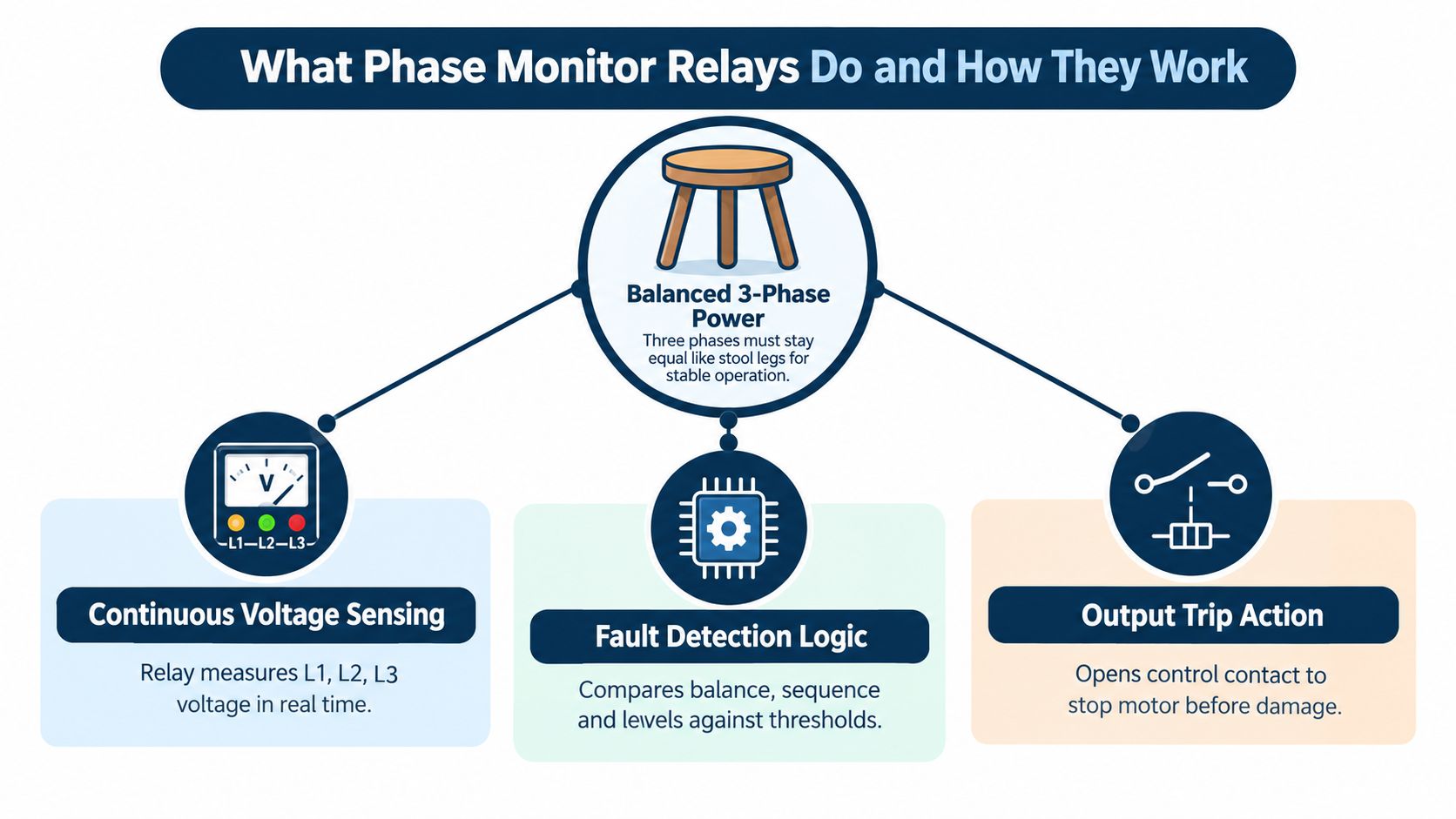
A phase monitor relay performs three jobs continuously:
- It senses the supply. Its sensing terminals connect to the relevant line conductors, and sometimes to neutral when the circuit requires neutral supervision.
- It evaluates the conditions. Internal logic checks phase presence, phase order, voltage levels, and the relationship between phases.
- It changes an output. A relay contact permits, interrupts, or reports the motor control circuit.
The relay usually sits in the control panel, with its sensing inputs connected to the line side or another defined feeder reference. Its output may operate the contactor control circuit or connect to a PLC input. Location matters. If the relay senses the wrong side of a disconnect, it can continue watching a healthy bus while a fuse in the protected branch has already opened.
Healthy power and failed power
Many industrial designs use a closed-circuit or energized-to-run principle. The relay output stays energized while the monitored supply is healthy. A detected fault, loss of relay power, broken control wire, or internal failure then de-energizes the output and sends the system toward a trip state. A wiring break is therefore treated as a fault instead of permitting operation.
The relay compares measured voltage with configured setpoints. Published three-phase monitor families can identify phase loss when one phase falls near 60% of nominal voltage. Other families detect phase sequence and phase failure below a specified fraction of nominal supply voltage, as described in the documented phase monitoring specifications. The exact threshold depends on the relay design and its settings.
A VFD may already perform similar input checks. In that case, a separate relay can duplicate drive protection at the motor branch. It still has a distinct role when the plant needs upstream contactor control, feeder-level alarming, or protection for loads and bypass paths outside the drive.
Terms that matter at the panel
Nominal voltage is the reference value used for comparison. Undervoltage means the measured supply has fallen below its permitted level. Overvoltage means it has risen above its configured limit. Asymmetry, also called phase unbalance, describes the difference between phase voltages or their electrical relationships.
Some relays use delay or hysteresis so the output does not chatter at a boundary. Hysteresis means the voltage needed to restore the healthy state can differ slightly from the voltage that caused the trip. That separation helps prevent repeated pickup and dropout during a fluctuating supply.
Practical rule: Treat the relay output as a permissive for operation, not proof that the motor is healthy. The overload device, drive protection, temperature monitoring, and mechanical safeguards still have separate jobs.
Core Protection Functions Every Relay Should Cover
A phase monitor relay should be selected around the feeder faults that can damage a load or defeat the plant's safety logic. Common devices supervise phase loss, phase sequence reversal, undervoltage, overvoltage, and phase unbalance. Some also monitor neutral interruption when the neutral provides a required reference or supply path. The technical description of the monitored conditions illustrates how one relay family combines these checks for three-phase and selected single-phase circuits.
The relay is therefore a feeder-level decision, not a motor accessory. A VFD may already check its incoming phases, making a second relay redundant at the motor branch for the same fault. The separate device still has a clear purpose when its contact must control an upstream contactor, generate a feeder alarm, or protect a bypass path and other loads outside the drive.
Phase loss
Phase loss occurs when one line is open or falls far below the other two. A blown fuse, loose termination, broken conductor, or damaged switching contact can cause it. The motor may keep turning, but its electrical loading becomes abnormal and heating can increase rapidly.
This fault normally calls for fast relay action because it indicates a definite feeder defect. One commercial device trips when a phase falls below 100 V, while healthy operation requires correct sequence and voltage above approximately 183 VAC, according to the published product information. Treat those values as device-specific, not as universal settings.
Phase sequence reversal
Phase sequence sets the direction of the rotating magnetic field. Interchanging any two incoming phases reverses motor rotation. That can create a mechanical hazard for pumps, compressors, fans, conveyors, and other equipment whose direction matters.
A sequence monitor blocks the start permissive when the order is incorrect. It does not repair the wiring. It prevents the contactor or drive enable from accepting a dangerous sequence after installation, rewiring, or maintenance.
Undervoltage
A weak utility source, overloaded feeder, poor connection, or another large motor starting nearby can pull the supply down. A short sag may be acceptable, whereas sustained low voltage can reduce motor performance and increase current stress.
Set a defined undervoltage threshold and add a time delay when the process can tolerate a short disturbance. A common configurable criterion is roughly 20% below nominal line-to-line voltage. The exact value must follow the relay range, the equipment rating, and the plant's operating conditions.
Remember: Phase loss usually needs fast action. Undervoltage often benefits from coordinated delay, because an immediate trip can convert a recoverable supply event into an unnecessary shutdown.
Overvoltage
Overvoltage adds electrical stress to motors, control transformers, and drive input stages. The relay compares the sensed supply with an upper limit and removes the healthy permissive when that limit is exceeded.
Check the incoming system and connected equipment before setting the limit. Undervoltage-only supervision cannot identify a sustained high-voltage condition, so overvoltage must be listed explicitly among the relay's functions.
Phase unbalance and neutral interruption
Phase unbalance exists when the three phase voltages differ beyond the load's acceptable range. All phases may still be present, yet the resulting negative-sequence effects can increase motor heating. Relay designs may provide an adjustable asymmetry setting or a fixed trip band, with the output changing state when the selected limit is exceeded, as documented in the manufacturer relay data.
Neutral interruption matters in systems that use neutral as a reference or supply conductor. A relay with neutral supervision can identify that failure instead of assuming the phase conductors describe the entire feeder condition. In the control architecture, use the relay output as a permissive or trip signal, while overload, drive, temperature, and mechanical protection continue to perform their separate jobs.
Wiring Diagrams and Setting Up Thresholds Correctly
A motor can stop even while the main bus still appears healthy. For that reason, wire the phase monitor relay at the feeder point whose condition must govern the motor permissive. Depending on the architecture, that point may be downstream of the feeder disconnect, after the branch fuses, or at a drive input. The relay is a feeder-level decision, not another accessory mounted beside the motor.
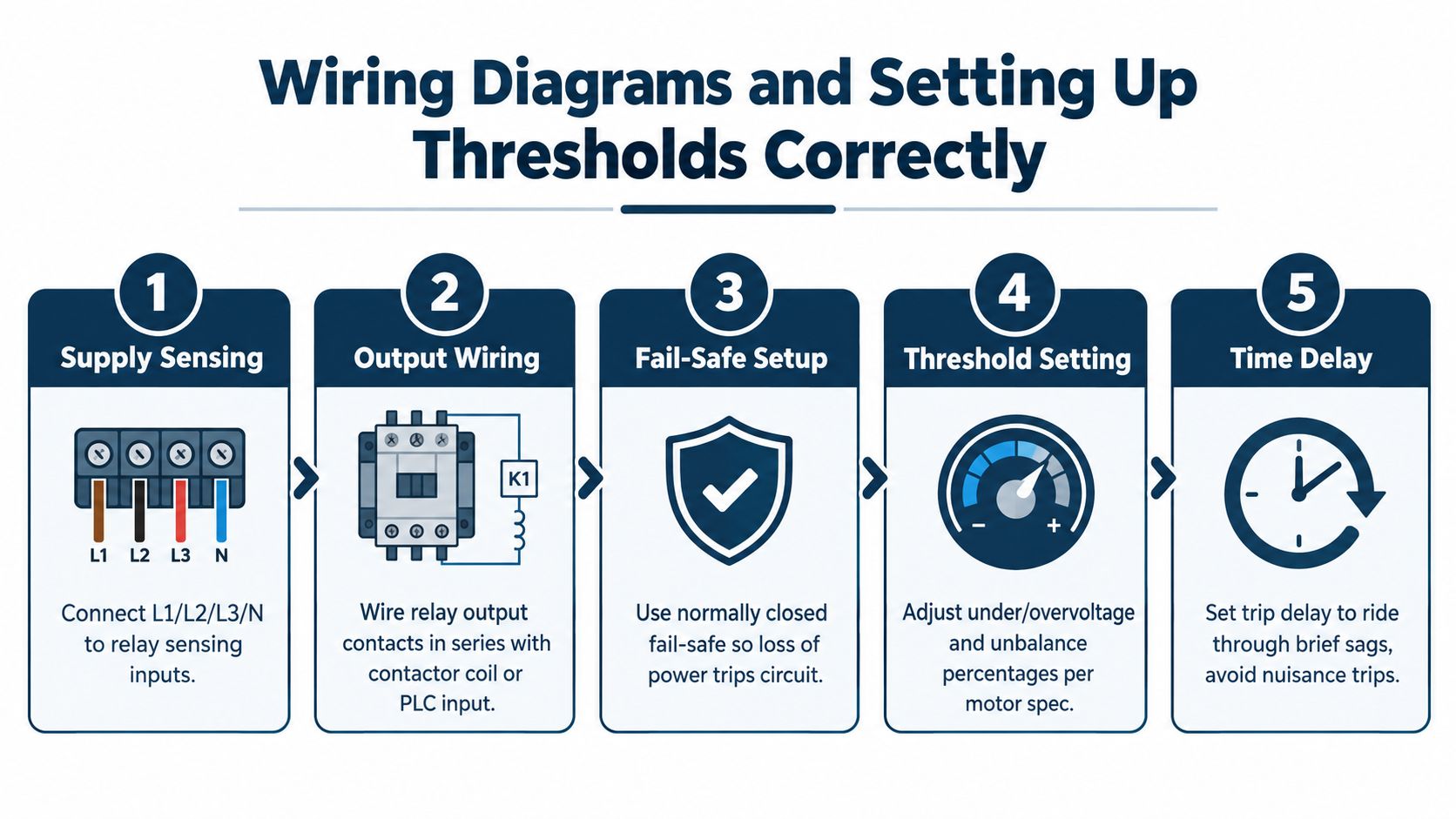
Connect the sensing inputs to the designated phase terminals, commonly L1, L2, and L3. Add neutral only when the relay and system design require it. Confirm the relay's voltage range before energizing, and verify that its sensing point matches the protection boundary. Identical-looking terminals do not prove that a relay suits the system voltage.
Put the output in the correct control path
The relay output normally becomes part of the motor's healthy permissive. In a traditional starter, wire the healthy contact in series with the contactor-coil control circuit. In a PLC-controlled panel, connect the contact to a suitable digital input or include it in the start-permissive logic. Use a hardwired trip path when the motor must drop out independently of software execution.
Choose the contact arrangement required by the design. If the relay must remain energized for the motor to run, loss of sensing power or a broken conductor removes the permissive. This arrangement catches a sensing-circuit failure that a software-only indication might leave unnoticed, especially when control power remains available after one feeder phase disappears.
Commission in a controlled sequence
- Confirm the wiring: Compare every sensing and output conductor with the approved schematic.
- Verify phase order: Measure and confirm the intended sequence before connecting the load.
- Enter the nominal reference: Use the relay's documented setting method, rather than estimating from a meter reading.
- Set voltage limits: Select under- and overvoltage thresholds from the equipment requirements, supply behavior, and coordination with other protection.
- Adjust unbalance: Choose a limit that protects the motor without reacting to harmless measurement noise or expected operating variation.
- Set delay: Use the shortest delay that tolerates known transient events, such as starting dips or feeder transfers.
- Test the trip: Simulate a phase loss, or use an approved test method with the motor isolated. Confirm that the contactor or permissive responds as designed.
For systems with a VFD, decide whether the external relay protects the feeder or duplicates the drive's internal monitoring. If the relay supervises upstream supply conditions or provides a permissive shared by several loads, its sensing point and output logic should reflect that role.
Document what the next technician needs
Record the relay part number, sensing point, nominal voltage, sequence, threshold values, delay values, output terminal numbers, and test result. Label whether the output is a healthy permissive, a fault signal, or both. A future technician should not have to infer the logic from terminal voltage alone.
Field habit: Test the relay at its actual terminal screws. Healthy voltage at the main bus does not prove that every fuse, terminal, and conductor feeding the relay is intact.
Selecting the Right Relay and Integrating With VFD Systems
Selection should begin with architecture, not with a list of features. Ask what the relay must stop, what it must report, and which device already owns each protection function.
A basic selection matrix looks like this:
| Requirement | Fixed-function relay | Adjustable relay | What to verify |
|---|---|---|---|
| System voltage | Suitable when the supply is stable and known | Useful across defined operating ranges | Nominal voltage and phase configuration |
| Phase-loss response | Simple and predictable | Allows coordination with the process | Published dropout behavior |
| Voltage thresholds | Consistent for standardized panels | Better for weak or variable feeders | Under- and overvoltage adjustment |
| Unbalance protection | Adequate for repeatable loads | Useful when load and grid conditions vary | Asymmetry range and measurement method |
| Output interface | Works for a defined control circuit | May provide more wiring flexibility | Contact arrangement and load compatibility |
The VFD question
A VFD may already detect input phase loss, undervoltage, and imbalance internally. If the drive is the only load involved, its internal fault handling may make an external phase monitor unnecessary for that particular function. That conclusion applies only when the drive's documented protection, fault response, restart behavior, and input sensing point meet the plant's requirements.
An external relay still has a clear role when protection must exist upstream of the drive or outside its software boundary. It can supervise a feeder before a bypass contactor, provide a hardwired permissive to a starter circuit, protect equipment during bypass operation, or send an independent condition to a PLC and safety-related shutdown design. It can also watch a common feeder serving several loads, where one drive's internal fault cannot supervise the rest of the panel.
| Application Scenario | VFD Internal Protection | External Relay Needed | Reasoning |
|---|---|---|---|
| One drive, no bypass path, drive protection meets the design | May cover the drive input conditions | Not always | Avoid duplicating the same sensing function without a defined benefit |
| Drive with a line-side bypass contactor | Applies only while the drive controls the motor | Usually | The bypass path needs its own feeder permissive |
| Shared feeder supplies multiple loads | Covers only the drive's input | Often | The feeder condition affects equipment beyond the drive |
| Hardwired contactor or safety permissive required | May report a fault through software | Often | The external contact can provide an independent control path |
| Maintenance isolation or upstream fuse monitoring | Cannot see every upstream wiring failure | Often | The relay senses the selected feeder location |
For drive-control background, review the VFD control methods guide alongside the electrical drawings. Coordinate the phase monitor with overload protection, circuit breakers, drive enable logic, and contactor feedback. Don't let two devices issue conflicting restart commands, and don't assume a drive fault output proves that an upstream feeder is healthy.
Troubleshooting Nuisance Tripping and Commissioning Tips
A relay that trips repeatedly may be identifying a real power-quality problem or exposing a setup error. Raising every threshold or bypassing the contact can restore production briefly, while removing the protection the feeder was designed to provide. Treat the trip as an event to investigate, not an inconvenience to suppress.
Start by recording the relay status, phase-to-phase voltages at the sensing terminals, motor state, drive state if present, and trip time. Compare those details with motor starts, compressor loading, capacitor-bank switching, feeder transfers, and utility disturbances. The timing often separates a genuine supply fault from a transient or wiring problem.
Match the delay to the load
A high-inrush motor can pull down the feeder during acceleration. A compressor skid may produce a different voltage profile from a lightly loaded pump, and a VFD input feeder can show switching behavior absent from a direct-on-line starter.
Set the shortest delay that allows a controlled start while still responding to a genuine fault. If the relay trips during acceleration, measure voltage at the relay terminals during the start instead of changing the setting by guesswork. If it drops out during normal running, inspect loose terminals, fuse condition, feeder impedance, capacitor-bank operation, and measured phase asymmetry.
Check the settings against the process
- For direct motor starters: Give phase-loss response priority, and confirm that the delay does not permit continued operation after a confirmed missing phase.
- For compressor packages: Review the start sequence, unloaded condition, and restart interlocks before selecting a longer ride-through period.
- For VFD input feeders: Confirm whether the drive already reports the same fault. Then decide whether the external relay protects an upstream path or only duplicates the drive's sensing.
- For unstable supplies: Trend the three-phase voltage and review fault history before changing the asymmetry or undervoltage limit.
- For capacitor-switched systems: Check whether switching events coincide with relay operation and whether the sensing point sees the resulting transient.
Public guidance on phase-failure relays consistently emphasizes delay settings, asymmetry limits, and sensitivity to capacitor banks. Apply those considerations to the actual feeder, sensing location, and process response rather than copying a generic setpoint.
Commission the whole control path
Test more than the relay LED. Confirm that a trip opens the intended contactor circuit, changes the PLC input, creates the correct alarm, blocks automatic restart when required, and records a usable event. Restore normal supply afterward and verify that re-energization follows the approved sequence.
Use the VFD commissioning checklist when a drive forms part of the installation. The relay should provide a defined signal within the plant's Smart O&M process, with its history retained rather than disappearing after a reset. DUCHENG Industrial's self-built monitoring platform can collect and store drive parameters in real time, support lifecycle analysis, and trend drive-condition indicators such as IGBTs, power units, and capacitor banks. Maintenance teams can use that information to compare relay events with drive alarms and operating conditions, helping distinguish feeder disturbances from drive-side faults.
Making Phase Monitoring Part of Your Protection Strategy
A phase-monitoring decision starts at the feeder, not at the motor accessory list. Ask which electrical conditions must remove power, which alarms only need operator attention, and which loads share the same supply. Phase loss, sequence, voltage, unbalance, and neutral supervision should match the feeder, load, and process response.
A relay can be useful at the point where a failure must be detected. Depending on the installation, that point may be upstream of a VFD, in a bypass circuit, within a contactor permissive, or on a shared feeder supplying several loads. If the VFD already detects the same fault and its trip signal enters the plant control logic, an external relay may duplicate protection. If upstream isolation, independent permissive logic, or protection during bypass operation is required, the relay serves a different purpose.
Treat the sensing location as part of the protection design. A relay installed ahead of a drive monitors the feeder and incoming supply. A drive-side function may instead report conditions that the drive itself can measure. Those signals should not be assumed equivalent.
Audit each panel by tracing sensing conductors, testing output logic, recording setpoints, and comparing drawings with installed wiring. Group settings by application rather than copying one value across every feeder. Link trips to maintenance records so repeated supply disturbances remain visible after reset.
Commission the complete control path. Confirm that a trip opens the intended circuit, changes the PLC input, generates the correct alarm, blocks automatic restart when required, and leaves a usable event record. The VFD commissioning checklist can support drive-related work.
DUCHENG Industrial supports VFD commissioning, troubleshooting, preventive care, repair, on-site reconditioning, spare-parts coordination, and monitoring architecture for industrial facilities. Assess the relay as part of the feeder protection and maintenance workflow.