
Compare VFD control methods from V/f to DTC and FOC. Learn how each works, trade-offs, and which method fits your motor and application.
A production line is running, but the motor speed is hunting whenever the load changes. On another machine, the drive reaches commanded speed yet loses torque at low speed. The fault may look like a bad motor, a weak drive, or a tuning problem. Often, the underlying issue is simpler: the selected VFD control method doesn't match the mechanical load, feedback arrangement, or maintenance capability.
A control strategy affects more than speed. It influences torque stability, low-speed behavior, response to changing load, commissioning effort, and the number of failure points that technicians must support. The drive brand matters, but the control mode, motor data, feedback design, and application settings usually decide whether the installation behaves well on the plant floor.
This guide treats each method as a practical engineering decision. If you're selecting a drive for a pump, fan, conveyor, compressor, winder, extruder, hoist, or machine tool, the useful question isn't which method is most advanced. It's which method delivers enough performance without creating unnecessary downtime risk. For background on the wider role of variable-speed drives, review this variable speed drive overview.
Table of Contents
- Introduction to VFD Control Methods and Why Selection Matters
- How VFD Control Methods Work From PWM to Vector Control
- Detailed Comparison of Major VFD Control Methods
- Sensor vs Sensorless Considerations for Plant Engineers
- Typical Applications and Use Cases by Control Method
- Tuning Commissioning and Implementation Insights
- How to Choose the Right VFD Control Method for Your Application
Introduction to VFD Control Methods and Why Selection Matters
A drive that runs an unloaded motor smoothly can behave very differently once the process is connected. A fan may tolerate gradual acceleration and modest speed accuracy, while a loaded conveyor may need stable torque during starting. A hoist adds another concern, because the control system must work with a mechanical brake and a carefully validated load-holding sequence.
The cost of choosing by habit
Many installations default to the control mode used on the previous machine. That can work when the motor, load, speed range, and operating cycle are similar. It fails when a replacement drive inherits assumptions from a different application.
Open-loop scalar control is attractive because it has fewer parameters and is easy to understand. Yet a method that works well on a centrifugal pump may produce weak low-speed behavior on a loaded conveyor. Sensorless vector control can improve that response, but it demands better motor data and more disciplined commissioning. Closed-loop vector control adds feedback and wiring, but it gives the control system a direct speed reference from the shaft.
Plant-floor rule: Select the simplest method that meets the process requirement, then commission it as carefully as a high-performance system.
Reliability is part of the control decision
A complex control mode doesn't automatically create a reliable machine. It can introduce more tuning dependencies, feedback hardware, alignment checks, and diagnostic conditions. Conversely, an overly simple method may cause nuisance trips, torque loss, or unstable speed regulation that repeatedly interrupts production.
The practical decision therefore has four parts:
- Performance: Can the drive maintain the required speed and torque through the operating range?
- Feedback: Does the application need an encoder, or can the drive estimate motor behavior acceptably?
- Commissioning: Can the maintenance team collect accurate motor data and complete the required tuning?
- Failure recovery: What happens if the encoder, cable, motor model, or drive parameter set becomes unreliable?
A good selection reduces both control error and maintenance ambiguity. It gives technicians a clear path for diagnosing whether the problem is mechanical, electrical, feedback-related, or parameter-related.
How VFD Control Methods Work From PWM to Vector Control
Modern VFD control methods share a common power-conversion foundation. The drive converts incoming AC power to DC, then uses switching devices to create a controlled output waveform for the motor. Pulse-width modulation, or PWM, is the common switching technique used across the major practical control families, including V/f, encoder-assisted V/f, open-loop vector, and closed-loop vector control, as described in the field-oriented control history and technical overview.
From six-step switching to PWM
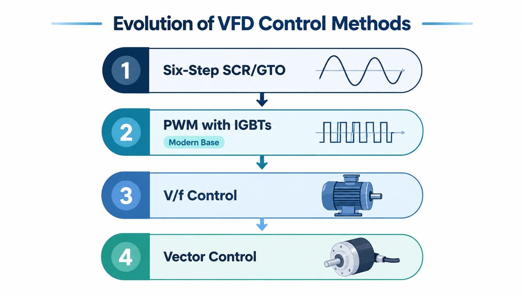
Early VFDs used SCRs or GTOs with variable-voltage inverter or current-source inverter designs. PWM drives appeared later, and the adoption of IGBTs in the late 1980s became a major step toward improved AC drive design, according to the historical review in this AC drive technology paper.
The improvement wasn't only about switching hardware. Better switching made it practical to shape motor voltage and frequency with much finer control. A technical history places PWM V/f control at a 1975 milestone and PWM flux-vector control at a 1985 milestone. Earlier PWM development began at Strömberg in Finland during the 1960s, with the concept sold to Helsinki Metro in 1973 and the first PWM drive becoming operational in 1982, as documented in the same historical source.
Scalar control and vector control
V/f control is scalar control. The drive maintains a relationship between output voltage and frequency, giving the motor an appropriate magnetic flux level as speed changes. It doesn't directly separate torque-producing current from flux-producing current, so its response is comparatively straightforward but less precise during rapid load changes.
Vector control, also called field-oriented control, works differently. It uses a motor model to treat flux and torque as separate control quantities. That separation gives the drive independent control of motor speed and torque, a behavior often compared with DC motor control in higher-performance applications.
The terms can confuse specifications. Sensorless vector usually means open-loop vector control, where the drive estimates rotor behavior without an encoder. Closed-loop vector uses encoder feedback to close the speed loop. Direct torque control is another high-dynamic approach, but product terminology varies, so engineers should verify the actual control architecture and feedback requirements in the drive documentation.
Detailed Comparison of Major VFD Control Methods
The four practical induction-motor control families are V/f, V/f with encoder, open-loop vector, and closed-loop vector. Each uses PWM, but they differ in how much information the drive has about the motor and how aggressively it regulates torque and speed.
| Control Method | Response Time | Speed Accuracy | Best Fit |
|---|---|---|---|
| V/f control | Slower dynamic response | Lower accuracy under changing load | Pumps, fans, and simple conveyors |
| V/f with encoder | Improved feedback response | Better than open-loop scalar control | Applications needing encoder-assisted speed regulation without full vector control |
| Open-loop vector | Faster response than scalar control | Better low-speed and transient behavior than V/f | General machinery with changing torque and no encoder |
| Closed-loop vector or FOC | Highest-performance response | Tightest speed and torque control | Winders, hoists, extruders, and precision machinery |
| DTC or direct torque control variants | High-dynamic torque response | Application-dependent, based on drive architecture | Loads requiring rapid torque changes |
The table summarizes qualitative behavior. The comparative study linked in this scalar and vector control analysis reports approximately 0.5 seconds response time, 6.66% speed error, and 20% THD for scalar control, compared with approximately 0.1 seconds, 2% error, and 5% THD for vector control. Those figures belong to that study and its test conditions, so they shouldn't be treated as a universal rating for every drive or motor.
V/f control
V/f remains the sensible choice when the load is forgiving. It has a simple control structure, modest tuning requirements, and fewer feedback-related failure modes. The trade-off is weaker torque regulation, slower correction after a load change, and less dependable low-speed performance.
For a pump or fan, those limitations may have little operational impact. For a conveyor carrying material from a standstill, they can become a recurring source of trips and production interruptions.
V/f with encoder
Encoder-assisted V/f adds measured shaft speed to a scalar strategy. It can improve speed regulation where the process needs feedback but doesn't justify a full vector implementation.
This method still requires careful encoder installation, cable shielding, signal verification, and fault planning. If the encoder is contaminated, miswired, or mechanically loose, the system may lose the very feedback advantage it was installed to provide.
Open-loop vector
Open-loop vector control estimates motor behavior from electrical measurements and a motor model. It typically gives better low-speed torque and transient response than V/f without the cost and wiring burden of an encoder.
Its weakness is dependence on accurate motor parameters and a valid model. A motor replacement, long cable, unusual motor construction, or incorrect nameplate entry can reduce the expected performance. It can be the right compromise for general machinery, but it isn't a substitute for encoder feedback where exact shaft regulation is essential.
Closed-loop vector and FOC
Closed-loop vector control uses encoder feedback to close the speed loop. This enables tighter control of speed and torque, making it appropriate for demanding applications with rapid load changes, low-speed operation, or positioning requirements.
The extra capability comes with extra commissioning and maintenance obligations. Encoder alignment, pulse quality, mechanical coupling, and cable integrity all become part of the reliability design.
DTC and direct torque control variants
Direct torque control focuses on rapid torque regulation rather than relying only on a conventional PWM reference structure. In practice, the useful comparison is not the label alone. Check how the drive handles motor identification, low-speed operation, regeneration, torque limits, feedback, and fault recovery under the actual load cycle.
The method that wins on a datasheet can lose on the floor if the maintenance team can't verify its feedback and motor model.
Sensor vs Sensorless Considerations for Plant Engineers
The sensor decision is a lifecycle decision, not merely a performance upgrade. An encoder can provide the information needed for tight speed and torque regulation, but it also adds a physical device, cabling, termination points, alignment requirements, and another failure path.
Closed-loop vector is the highest-performance option in the common control hierarchy because encoder feedback closes the speed loop. Open-loop vector improves low-speed torque and transient response without that feedback hardware, which is why it often suits machinery that needs more capability than V/f but doesn't require exact shaft-speed control. These distinctions are described in the industrial drive control comparison.
When an encoder earns its place
Use encoder feedback when the process depends on the motor shaft doing exactly what the command requires. Typical examples include a winder that must maintain tension, a hoist that needs controlled low-speed torque, or a machine tool that must coordinate motion with another axis.
The encoder should be treated as part of the control loop, not as an accessory. A loose coupling, damaged cable, poor shielding, contaminated sensor, or incorrect pulse configuration can create speed oscillation, feedback loss, or unexplained torque behavior.
When sensorless is the better reliability choice
Sensorless control removes the encoder and its field wiring. That can be valuable in areas with vibration, dust, chemical exposure, high salinity, or limited access to the motor. Fans, pumps, and many general-purpose machines often don't need shaft feedback, especially when the process responds slowly to speed variation.
The absence of an encoder doesn't remove commissioning work. The drive still needs correct motor voltage, current, frequency, speed, power, and other nameplate information. Autotuning and motor-model identification become especially important because the drive estimates behavior rather than measuring shaft speed directly.
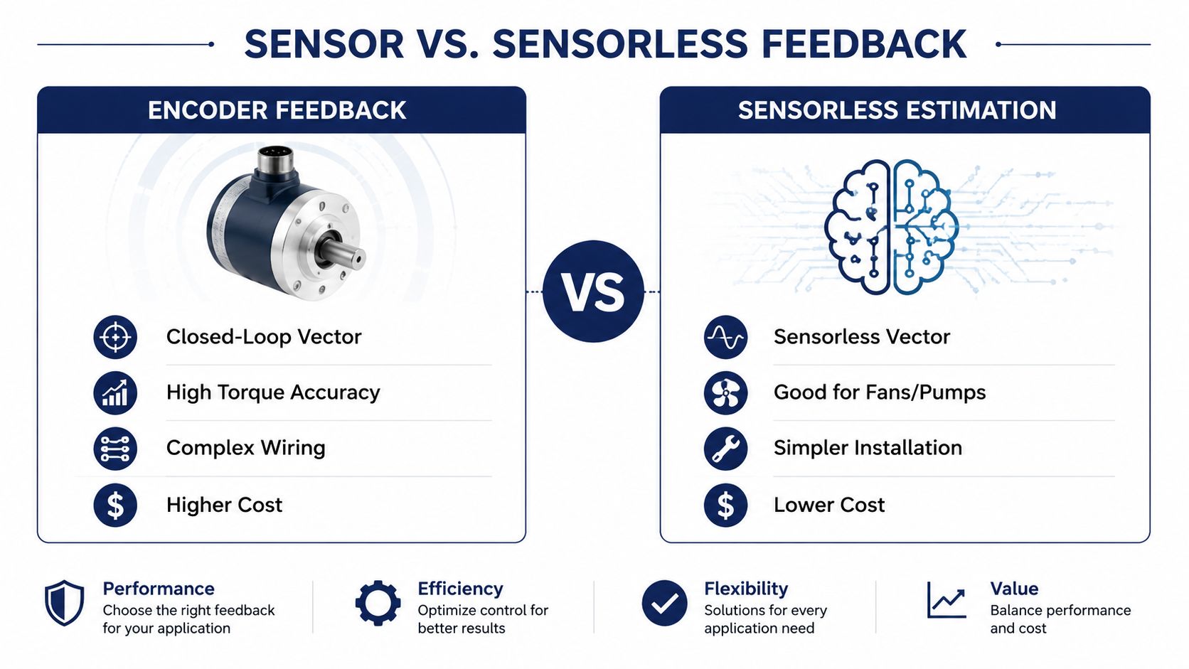
The practical trade-off is clear. Encoder feedback buys control authority, while sensorless operation removes hardware that can fail. Choose feedback when a control error threatens product quality, safety, or mechanical stability. Choose sensorless operation when the load is tolerant and environmental simplicity matters more than maximum regulation.
The following video provides a visual introduction to motor feedback and drive behavior.
<iframe width="100%" style="aspect-ratio: 16 / 9;" src="https://www.youtube.com/embed/2WSyo-4nXV8" frameborder="0" allow="autoplay; encrypted-media" allowfullscreen></iframe>Typical Applications and Use Cases by Control Method
The same motor can be a good candidate for different VFD control methods depending on the driven equipment. A motor on a centrifugal fan usually sees a gradual torque demand. The motor on a loaded conveyor may face a sudden breakaway requirement. The motor on a hoist must manage torque, low-speed movement, brake coordination, and load behavior.
V/f for forgiving loads
V/f control is usually appropriate when the load doesn't require tight speed regulation or rapid torque correction.
- Fans and pumps: The process often tolerates gradual acceleration and modest speed variation.
- Simple conveyors: Use it when the conveyor starts lightly loaded and doesn't require precise speed matching.
- Basic ventilation systems: The reduced control complexity can simplify commissioning and fault diagnosis.
A pump still needs correct ramp settings and protection. A simple control method doesn't excuse poor motor sizing, inadequate cooling, or incorrect current limits.
Sensorless vector for general machinery
Sensorless vector is a useful middle path. It can support better starting torque and improved transient behavior without installing an encoder on the motor.
Consider it for a compressor, mixer, or loaded conveyor where the motor sees changing torque but exact shaft synchronization isn't required. An extruder may also benefit when low-speed torque matters, although the final decision should account for starting load, thermal duty, speed range, and process control requirements.
The main risk is expecting sensorless estimation to behave like measured feedback. If the process demands exact speed at very low speed, the application may need a closed-loop design.
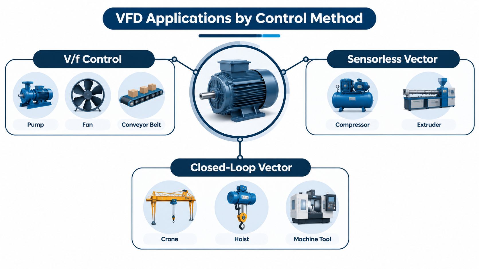
Closed-loop vector for demanding motion
Closed-loop vector belongs on applications where speed or torque error directly affects the process.
- Winders and unwinders: Feedback helps maintain stable material behavior as the roll condition changes.
- Hoists and cranes: Encoder feedback supports controlled movement, but it must work with a properly designed mechanical brake and safety system.
- Machine tools: Tight regulation and repeatability can justify the added wiring and commissioning effort.
- Precision extruders: Feedback may be appropriate when output quality depends on stable shaft speed and torque.
A practical decision matrix
| Application condition | Preferred direction | Main reason |
|---|---|---|
| Smooth, variable-torque load | V/f | Simple control is often sufficient |
| Changing torque without exact synchronization | Sensorless vector | Better response without encoder hardware |
| Tight low-speed speed control | Closed-loop vector | Measured shaft feedback |
| Rapid torque changes | Vector or DTC variant | Higher dynamic control capability |
| Harsh motor location with tolerant process | Sensorless | Fewer field devices and cables |
Treat the matrix as a starting point, not a substitute for load data. A commissioning engineer should confirm inertia, speed range, breakaway torque, stopping behavior, and the consequences of a feedback or control fault before approving the method.
Tuning Commissioning and Implementation Insights
Control selection only pays off after commissioning converts the drive's model into a working machine. The most common avoidable problems start with incorrect motor nameplate data, skipped tuning, unsuitable acceleration limits, or feedback installed without alignment verification.
Build the motor model correctly
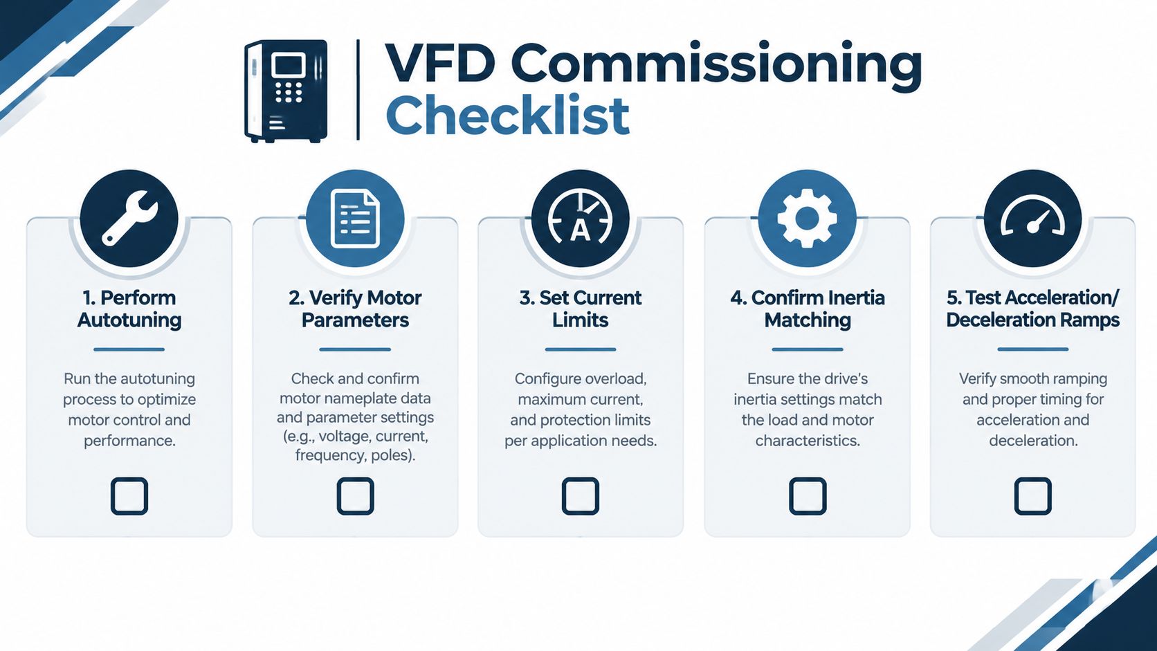
Enter the motor data exactly as shown on the nameplate and confirm that the selected motor matches the drive's voltage and current assumptions. If the drive offers static and rotating autotune, select the option that fits the mechanical condition and site safety requirements. A rotating test can provide useful information, but it isn't appropriate when the machine can't turn safely or when the load must remain mechanically isolated.
Autotuning doesn't correct bad data. It also won't compensate for a motor with damaged bearings, incorrect connections, or a mechanical load that was never inspected.
Check the control loop under real load
Start with conservative acceleration and deceleration settings, then observe current, speed, torque, and fault history while the process moves through its normal operating range. A machine that runs correctly with no load may still reveal inadequate torque margin once material, pressure, tension, or static friction is present.
For encoder systems, verify direction, pulse count, signal quality, mechanical coupling, and alignment. An encoder that reports the wrong direction can make a stable loop behave like a regenerative one. Oscillation after maintenance often points to an altered feedback relationship, changed motor data, or a parameter set that wasn't restored correctly.
Use this VFD commissioning checklist to support a documented startup and handover process.
Leave a recovery record
Record the final motor parameters, control mode, autotune result, feedback settings, current limits, ramp values, and any application-specific limits. After motor or drive maintenance, verify the active parameter set against that record before restarting.
A stable restart begins with evidence. Capture the fault, preserve the parameters, inspect the load, and only then change the control settings.
This approach prevents repeated resets from hiding a mechanical problem or a feedback fault. It also gives the next technician a reliable baseline instead of a collection of undocumented adjustments.
How to Choose the Right VFD Control Method for Your Application
Start with the load, not the drive menu. If the machine is a pump, fan, or forgiving conveyor and doesn't need tight regulation, begin with V/f. If the machine needs stronger low-speed torque or better response to changing load but can tolerate estimated speed, evaluate open-loop vector.
Choose closed-loop vector when speed or torque error affects safety, product quality, tension, synchronization, or positioning. Accept the additional encoder hardware only when the process benefit justifies the installation, alignment, testing, and maintenance burden. Consider DTC or another direct torque approach when the load demands fast torque changes and the selected drive supports the required operating range and commissioning tools.
Before approval, document:
- Load behavior: Breakaway torque, inertia, overhauling tendency, and operating cycle.
- Speed requirement: Normal range, low-speed duty, synchronization, and stopping behavior.
- Maintenance reality: Environmental exposure, access to the motor, feedback cable routing, and available diagnostic skills.
- Failure consequence: Product loss, mechanical damage, safety exposure, or a tolerable process slowdown.
- Lifecycle support: Parameter backup, preventive inspection, spare-part compatibility, repair capability, and restart assistance.
DUCHENG Industrial provides multi-brand VFD commissioning, troubleshooting, preventive care, workshop repair, on-site reconditioning, and spare-parts verification for industrial drive systems. Those services are relevant when a control-method decision must be supported through startup, planned shutdowns, late-life maintenance, or an unplanned trip.
Review the application with the motor and load data in hand, test the selected method under real operating conditions, and document the final settings before handover. For commissioning, repair, or lifecycle support across industrial VFD assets, visit DUCHENG Industrial and submit the drive and application details for assessment.