
Understand how a variable speed drive works, where it saves energy, and what lifecycle costs and reliability risks plant teams actually face
A critical motor trips halfway through a production run. The operator sees an overcurrent alarm, the process line stops, and three questions arrive at once: can the drive be reset, what caused the trip, and how long can the plant tolerate the risk of another restart? In a steel, tire, or chemical facility, the answer rarely comes from the fault code alone.
A variable speed drive is more than an energy-saving accessory. It's a power-electronic asset that shapes motor torque, controls process output, and absorbs electrical, thermal, and environmental stress every time it runs. The installation may have started with a simple payback calculation, but its real value depends on harmonic performance, cooling, contamination control, maintenance discipline, and the quality of decisions made when the drive reaches late life.
Table of Contents
- Why Variable Speed Drives Matter on the Plant Floor
- How a Variable Speed Drive Actually Controls Motor Speed
- Key Components and Hidden Stress Points Inside the Cabinet
- Where Variable Speed Drives Deliver the Biggest Process Benefits
- Energy Savings and Power Quality Economics
- Repair, Recondition, or Replace Aging Medium- and High-Voltage Drives
- Lifecycle Best Practices for Reliable Variable Speed Drive Operation
Why Variable Speed Drives Matter on the Plant Floor
A drive trips during a high-demand production window. Production pressure immediately shifts to the electrical team, and the fastest-looking action is often a reset. That may restore motion briefly while leaving a blocked cooling path, weakened capacitor bank, mechanical jam, or power-quality fault untouched. A controlled diagnosis protects the process and the drive from a second failure.
Plant processes rarely need motors to run at one fixed operating point. Pump flow changes with production demand. Fan pressure changes as filters load. Conveyors need controlled acceleration to protect belts and gearboxes, while tire lines depend on stable speed and tension for consistent product dimensions. A variable speed drive matches motor operation to those changing conditions.
The drive affects more than speed
A drive regulates motor output at the source instead of forcing full motor output against a downstream valve, damper, or mechanical restriction. That can reduce wasted process energy. It also provides controlled starting, repeatable acceleration, torque regulation, and communication with plant control systems.
The same power electronics introduce operating stresses that affect lifecycle cost. Switching devices generate heat, and the input stage can draw harmonic current into the plant network. The output waveform adds demands on motor insulation, cable routing, grounding, and sometimes bearing protection. Dust, salt, carbon black, chemical residue, and restricted airflow can turn a correctly selected drive into a recurring maintenance problem.
Practical rule: Treat every drive trip as both a control event and an electrical-maintenance event. The alarm identifies where protection acted, not necessarily why the process became unsafe.
The scale of industrial drive use is substantial. European industrial estimates put variable speed drives at about 265 TWh of electricity converted into application-specific motor output in 2015, associated with 105 Mt of CO2 emissions. Projections described in the same data place that output at around 380 TWh by 2020 and 570 TWh by 2030. The figures show the technology's broad industrial role, not a guaranteed return for an individual installation. Actual results depend on load profile, control strategy, harmonics, motor condition, and maintenance.
The engineer's job extends beyond selecting a rated current. Load behavior, network strength, enclosure cooling, motor insulation, contamination exposure, access for inspection, and the consequence of failure all affect the decision. A drive that operates for years in a clean room may require different cooling, filtering, and inspection practices in a steel, tire, or chemical plant.
Late-life decisions also belong in the original design discussion. A repair or reconditioned power section may preserve a sound cabinet and known application, while replacement can make sense when insulation stress, obsolete controls, or repeated thermal faults have changed the risk. That lifecycle view determines whether the drive remains dependable when the production window matters most.
How a Variable Speed Drive Actually Controls Motor Speed
Think of a variable speed drive as a smart electrical throttle. A valve restricts fluid after a pump has already produced pressure, while a drive changes the electrical conditions that make the motor produce its output in the first place. The drive doesn't turn power down. It reconstructs the power supplied to the motor so the process can run at the required speed and torque.
The three power stages
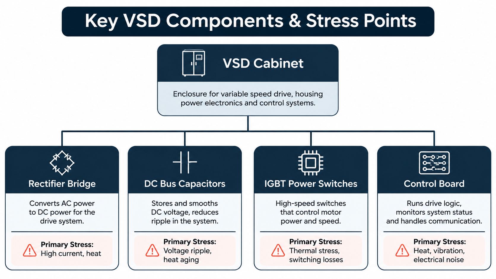
Incoming alternating current first enters the rectifier. Diodes or controlled switching devices convert the fixed-frequency AC supply into DC. This stage establishes the electrical foundation for the drive, but it also draws current in pulses, which is one reason input harmonics become an important design issue.
The rectified energy then reaches the DC bus. Bus capacitors smooth the voltage and provide a short-term energy reservoir between the input and output stages. They also experience ripple current and heat, so their condition has a direct effect on reliability.
The inverter uses high-speed power switches, commonly IGBTs in many industrial designs, to turn the DC bus voltage on and off in carefully timed patterns. Pulse-width modulation creates an AC output with the requested frequency and voltage. The motor responds to the fundamental component of that waveform, while the switching pattern and installation details influence heat, electromagnetic interference, insulation stress, and bearing-current risk.
What the control system changes
The drive receives a speed or torque command from a local interface, hardwired signal, or plant control system. Its control software compares the requested condition with feedback, then changes the switching pattern to regulate motor behavior.
At lower frequency, the drive generally reduces voltage as well, maintaining a usable relationship between magnetic flux and motor operation. At higher loads, it may increase output current within its programmed limits to produce the required torque. The exact control method depends on the application and motor, but the operational principle remains the same: the drive controls the electrical waveform, and the motor converts that waveform into controlled mechanical output.
This conversion introduces losses at the rectifier, DC bus, and inverter. It also changes the current waveform seen by the supply and the voltage waveform seen by the motor. A plant can therefore gain process efficiency while still creating new thermal and power-quality obligations.
A useful troubleshooting distinction follows. A fault on the DC bus points you toward capacitors, precharge circuits, input conditions, or excessive regeneration. An inverter overcurrent alarm may involve acceleration settings, a mechanical load, motor insulation, output cabling, or a failing power module. The drive is the messenger for several systems, not an isolated black box.
Key Components and Hidden Stress Points Inside the Cabinet
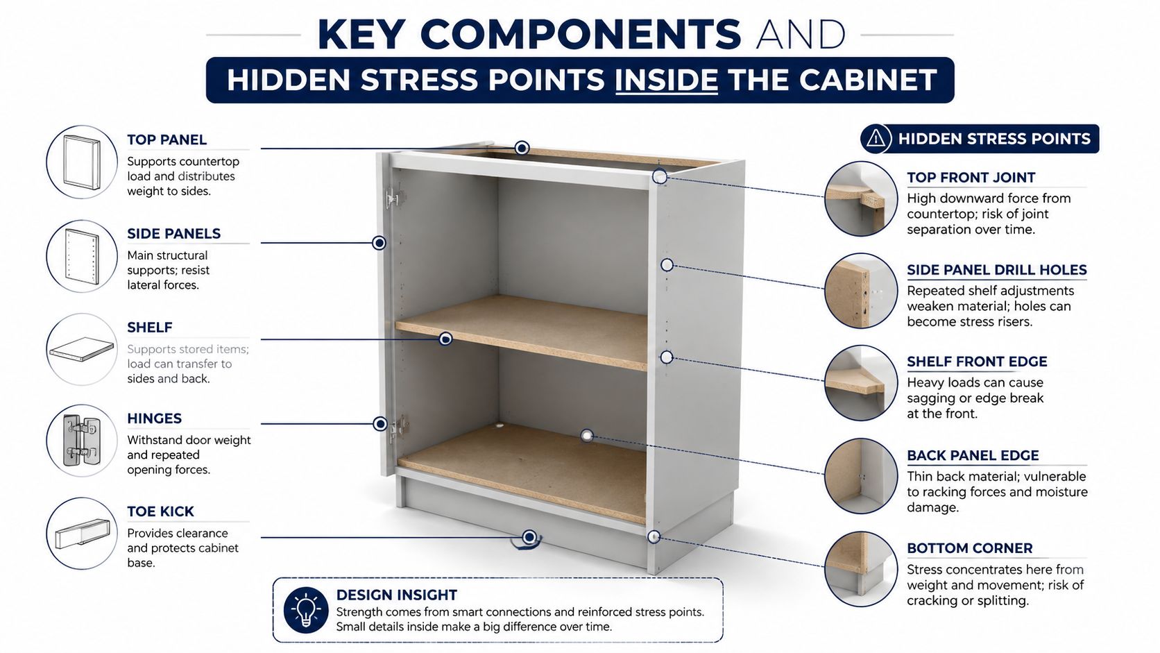
The cabinet's most vulnerable parts are usually the ones handling heat, ripple current, switching energy, and contamination. Replacing a failed module without correcting those conditions often produces a short-lived repair.
What maintenance teams should inspect
The rectifier bridge handles the incoming conversion duty. Weak input connections, supply disturbances, and repeated thermal cycling can stress the bridge and its associated protection. A line reactor or other input-side mitigation may be appropriate where the network requires it, but the choice has to follow a site assessment rather than a generic parts list.
DC bus capacitors age through temperature, voltage stress, and ripple current. Their failure can appear as bus undervoltage, overvoltage, excessive ripple, or an explosive physical event. Visual inspection matters, but it isn't sufficient. Capacitance, equivalent series resistance, bus ripple, and discharge behavior should be assessed using procedures suited to the specific drive.
The inverter power modules switch the DC energy into motor power. Their junction temperature rises with current and switching frequency, then falls as the load changes. That repeated thermal cycling can weaken solder joints, bond wires, and module interfaces. A drive that only trips at peak production load may be exposing a marginal thermal path rather than an incorrectly configured control loop.
Contamination is an electrical problem
Dust and conductive residue settle on heat sinks, filters, bus insulation, terminal blocks, and control boards. Carbon contamination is especially troublesome because it can combine with moisture and create leakage paths. Salt-laden air creates a similar risk in coastal facilities, while chemical vapors can attack coatings, seals, and metal surfaces.
Cooling fans and filters deserve the same attention as power components. A blocked filter forces the fan to move less air, while a failing fan allows the heat sink and power modules to run hotter. Thermal protection may prevent immediate destruction, but repeated overtemperature events accelerate aging and interrupt production.
Loose connections are another recurring cause of trouble. Vibration and thermal expansion can increase resistance at terminals, producing localized heating that worsens the connection. Infrared inspection under representative load, torque verification during shutdowns, and examination for discoloration or insulation damage provide more useful evidence than tightening everything indiscriminately.
The strongest preventive program manages the conditions that create failure, especially heat, contamination, vibration, and electrical stress.
The control board and feedback circuits can fail in less dramatic ways. A sensor reference may drift, a communication interface may drop out, or a board may become unreliable as cabinet temperature rises. Maintenance records should connect these intermittent symptoms with cabinet conditions and operating load, rather than treating each alarm as a separate mystery.
Where Variable Speed Drives Deliver the Biggest Process Benefits
The best application is one where the process needs changing speed, not one where a drive is added because every modern motor project is expected to include one. The benefit can be energy reduction, but it can also be controlled torque, smoother starting, better product consistency, or tighter regulation of flow and tension.
| Load Type | Typical Applications | Primary Benefit |
|---|---|---|
| Variable torque | Pumps, fans, and blowers | Matching motor output to changing flow or pressure demand |
| Constant torque | Conveyors, mixers, and some extruders | Controlled speed, starting torque, and process coordination |
| High inertia | Large fans, centrifuges, and heavy rotating equipment | Managed acceleration and reduced mechanical shock |
| Tension-sensitive | Web handling, tire processing, and rolling equipment | Stable speed relationships and product control |
| Pressure-sensitive | Chemical pumping and process ventilation | Responsive regulation without constant mechanical throttling |
Variable-torque loads
Pumps and fans are usually strong candidates when demand changes across the operating cycle. A drive can reduce motor speed instead of running at full speed against a partially closed valve or damper. The value depends on the actual duty profile, the control range, bypass operation, minimum flow requirements, and whether the equipment spends meaningful operating time below full speed.
A cooling-water pump in a chemical facility may benefit from direct pressure control, but the engineer still has to protect minimum flow and avoid unstable operation. A fan in a dusty process may need speed control to maintain draft, yet the enclosure and filter arrangement must withstand the environment.
Constant-torque and high-inertia loads
Conveyors, mixers, positive-displacement equipment, and extruders often need torque even when speed falls. The drive must be selected and programmed for the actual load, including acceleration demand, product buildup, jam-clearing requirements, and regenerative behavior during deceleration.
In a tire plant, controlled acceleration can reduce belt and gearbox shock while keeping line coordination stable. In a steel application, speed regulation may matter more than reduced energy use because the drive helps coordinate rolls, tension, and downstream equipment. A high-inertia fan may need a carefully managed ramp, braking strategy, and mechanical review rather than a simple start command.
When a simpler solution is better
If a motor always runs at one speed and the process doesn't need controlled acceleration, a fixed-speed starter may involve less equipment and fewer maintenance obligations. A soft-starting arrangement may suit a motor that only needs reduced starting stress, while a drive adds value when continuous speed control or process feedback is required.
Before approving a drive, ask:
- Load behavior: Does the process need variable speed, or only a controlled start?
- Torque demand: Will the motor need constant torque at reduced speed?
- Operating profile: How often will the motor run below full speed?
- Environment: Can the cabinet manage dust, heat, moisture, and corrosive exposure?
- Network impact: Has the plant power system been assessed for harmonics and added RMS current?
- Failure consequence: Is there a bypass or recovery strategy if the drive trips?
That checklist prevents energy savings from becoming the only justification.
Energy Savings and Power Quality Economics
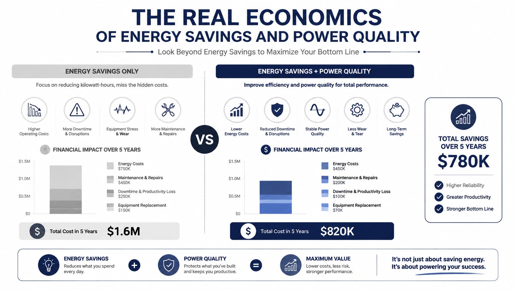
A drive project can look profitable until the plant accounts for harmonic mitigation, enclosure cooling, derating, motor protection, spare parts, and maintenance access. Those costs do not disqualify the technology. They define the business case more accurately, especially in steel, tire, and chemical facilities where heat, contamination, and downtime affect the asset long after commissioning.
Harmonics change the project calculation
IEEE 519-2022 is widely used for industrial power systems. At the point of common coupling, projects commonly target 5% voltage THD, while acceptable current distortion depends on system strength and short-circuit ratio. This VFD harmonics and IEEE 519 reference explains why a six-pulse drive can produce excessive harmonic current on a weak plant bus even when the motor is running normally.
Standard six-pulse drives can exhibit roughly 35% to 80% current THD. Lower-harmonic front ends and multi-pulse arrangements reduce distortion, but they add transformer or rectifier complexity. Harmonic current increases RMS loading and can raise temperatures in transformers, cables, and switchgear. It can also stress capacitor banks and contribute to nuisance relay operation.
The design question is not whether the drive satisfies a brochure specification by itself. Verify whether the complete installation performs acceptably at the common coupling point under actual plant conditions, including other nonlinear loads and lightly loaded operating periods.
Count losses beyond the drive nameplate
Drive efficiency figures can appear closely grouped. Typical efficiencies around 96% to 97% are reported for common harmonic-mitigation configurations, yet system losses may still increase through higher RMS current and network heating. At 40% THDi, RMS current losses increase by about 16% compared with a system without harmonics, according to this technical discussion of drive efficiency and harmonic losses.
That distinction belongs in the project review. Compare the energy saved by changing motor speed with the energy and maintenance burden of filters, reactors, cooling equipment, harmonic-rated transformers, and added inspection requirements. Then assign value to process performance. Improved pressure stability or product quality can justify a drive when the energy reduction is modest.
A credible lifecycle calculation should include:
- Operating benefit: Reduced throttling, better control, and lower mechanical stress where the duty profile supports them.
- Electrical cost: Harmonic studies, mitigation equipment, derating, and possible network upgrades.
- Thermal exposure: Cabinet cooling, fan replacement, filter service, and heat-related component aging.
- Downtime risk: Trip consequences, bypass availability, and the time needed to obtain compatible parts.
- Late-life strategy: Whether the drive can be repaired, reconditioned, or upgraded without replacing the complete system.
Industry reports place 2025 global variable frequency drive market estimates between about USD 24.7 billion and USD 28.1 billion, with 2030 projections between about USD 32.0 billion and USD 36.3 billion, as summarized in this variable frequency drive market overview. Market growth does not settle a plant-specific decision. Site conditions, power quality, thermal stress, contamination, and the cost of late-life recovery determine whether the drive delivers value over its service life.
Repair, Recondition, or Replace Aging Medium- and High-Voltage Drives
When an aging medium- or high-voltage drive starts faulting, replacement is often proposed before anyone has established whether the power modules, capacitors, cooling system, controls, and insulation are beyond recovery. That approach can be sensible for obsolete equipment, but it can also create unnecessary logistics, integration work, and commissioning exposure.
APAC illustrates why late-life service deserves more attention. The region's VFD revenue was about USD 10.47 billion in 2025, low-voltage units held 86.9% share, and medium-voltage drives were forecast to grow fastest at 6.85% CAGR through 2031, according to this Asia-Pacific variable frequency drive market analysis. Those figures point to a large installed base and an expanding need to manage aging assets, not just install new ones.
Start with evidence, not preference
A defensible decision begins with operating history and condition evidence:
- Review the failure pattern. Separate one-off process events from recurring overtemperature, overvoltage, communication, or insulation-related faults.
- Inspect the environment. Record contamination, moisture, corrosion, airflow restriction, fan condition, and evidence of overheating.
- Test serviceable subsystems. Assess capacitors, power modules, gate-drive circuits, control boards, cooling equipment, protection circuits, and insulation as applicable.
- Check obsolescence. Identify whether critical boards, sensors, firmware, and power modules remain available and compatible.
- Set the downtime boundary. Compare the cost of a planned shutdown with the risk of an uncontrolled failure during production.
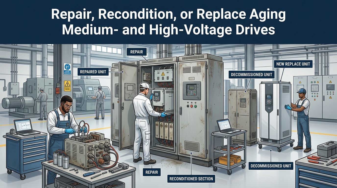
Workshop repair makes sense when the unit can be safely removed and the failure is localized. It allows controlled disassembly, bench diagnostics, component-level repair, and functional testing, but shipping a large drive can create handling and transport risk.
On-site reconditioning is often more practical for critical medium- and high-voltage equipment. Technicians can clean, inspect, test, renew serviceable subsystems, and verify the installation during a planned shutdown. That path reduces transport exposure, but it requires proper isolation, qualified personnel, test equipment, access, and a clear restoration plan.
Replacement is one option, not the default
Replacement becomes more compelling when the control architecture is obsolete, critical parts cannot be verified, the drive has suffered major insulation or structural damage, or the process requires capabilities the existing system can't provide. It also makes sense when repeated repairs have failed to address the root cause.
For a practical service pathway covering industrial drive diagnosis and repair decisions, review industrial drive service. The decision should document why each path was accepted or rejected, including compatibility, restart risk, commissioning requirements, and the availability of an exchange unit.
Decision point: If shipping the drive is riskier than working on it in place, the shutdown plan should evaluate on-site reconditioning before it assumes full replacement.
Lifecycle Best Practices for Reliable Variable Speed Drive Operation
Reliable drives come from disciplined routines, not from a single commissioning test. The plant should manage the asset from the first energization through every restart, shutdown inspection, repair, and replacement decision.
Build the routine around failure prevention
- Commission with evidence: Record motor data, protection settings, ramp behavior, feedback performance, network signals, harmonic measurements, and baseline temperatures.
- Restart under control: Use a production escort during critical windows. Confirm the fault history, mechanical condition, cooling path, and permissives before applying a reset.
- Inspect during shutdowns: Remove contamination safely, check fans and filters, examine terminals, inspect capacitors, and verify thermal conditions.
- Protect compatibility: Identify exact board, module, sensor, and firmware requirements before ordering a spare. A physically similar part isn't automatically a safe substitute.
- Monitor changing condition: Use trend data and suitable O&M or IoT architecture to identify rising temperatures, cooling deterioration, capacitor aging, insulation concerns, or repeated fault precursors.
A structured VFD maintenance schedule should connect inspections to operating conditions and failure history. It should also define who can authorize a restart, what evidence is required, and when a recurring fault must move from operations to engineering investigation.
The most effective teams don't treat a drive as a sealed appliance. They maintain the cabinet environment, validate the power system, preserve configuration records, and keep a late-life plan for repair, on-site reconditioning, upgrade, or replacement. That approach reduces reactive decisions and protects production when the next trip occurs.
DUCHENG Industrial provides multi-brand VFD commissioning support, controlled restart assistance, workshop repair, preventive care, and on-site reconditioning for medium- and high-voltage drive systems across China and Southeast Asia. If your plant is dealing with recurring trips, harsh contamination, obsolete parts, or an upcoming shutdown, visit DUCHENG Industrial to discuss a practical lifecycle service plan.