
VFD explained clearly — how drives work, where they save energy, and how to keep them reliable from commissioning to reconditioning.
You've seen the setup a hundred times. A pump motor runs flat out all shift, the discharge valve stays partly closed, and the process operator trims flow with the valve because that's how the line has always been run. The motor is doing full work. The process only needs part of it. The extra energy turns into pressure drop, heat, and wear.
That's the problem a Variable Frequency Drive, or VFD, solves when the application is right. Instead of forcing a motor to run at one fixed speed and then wasting part of its output mechanically, a VFD changes the electrical supply to the motor so the motor itself runs at the speed the process needs.
People often treat drives like sealed black boxes. They know the keypad changes RPM, they know alarms appear, and they know someone gets called when the trip won't reset. But if you understand the cause and effect inside a drive, you make better decisions at every stage: specification, commissioning, fault finding, maintenance, and late-life renewal.
Table of Contents
- Introduction What a VFD Actually Does for Your Motor
- How a VFD Controls Motor Speed Without Wasting Energy
- Inside the Drive How AC Becomes DC and Back to Controlled AC
- Real Savings Versus Hidden Costs Harmonics and Power Quality
- Where VFDs Deliver Value Across Industrial Applications
- Why Drives Fail and How Lifecycle Care Prevents Downtime
- Key Takeaways for Reliable VFD Operation From Start Up to Renewal
Introduction What a VFD Actually Does for Your Motor
In plain language, a VFD is an electronic speed controller for an AC motor. It lets the motor speed move with demand instead of staying tied to the fixed frequency of the incoming power supply.
That sounds simple, but the practical effect is huge. On many pump and fan systems, reducing speed is far more efficient than running full speed and throttling output. Industry guidance notes that VFDs are most effective in pump and fan duty because power demand falls roughly with the cube of speed, and typical energy savings in high-run-hour industrial use often land in the 20% to 50% range, while the drive itself usually operates at about 97% to 98% efficiency. That means most of the savings come from better system matching, not from magic inside the hardware (energy performance guidance for VFD motor systems).
A familiar plant example
Take a cooling-water pump. The process needs less flow at night, but the motor still runs at full rated speed. The operator closes the valve to reduce flow. The line pressure rises, the valve eats the pressure drop, and the motor keeps drawing power to create flow you're deliberately choking back.
Install a VFD on the same duty, and the control loop can ask for less speed instead of more restriction. The pump does less hydraulic work because the process needs less hydraulic work.
A valve controls flow by wasting part of the pump's output. A VFD controls flow by reducing how much output the pump creates in the first place.
Why this matters beyond energy
First learn about VFDs through energy‑saving projects. That's fair, but it's incomplete. Drives also affect:
- Process control: You can hold pressure, flow, or airflow more smoothly.
- Mechanical stress: Starts and speed changes can be gentler than direct full-speed operation.
- Electrical behavior: The drive changes what the motor sees and what the supply system sees.
- Maintenance strategy: Electronics age differently from motors, contactors, and valves.
That last point gets skipped too often. The global VFD market is large enough that it's now a mainstream industrial asset category, with one estimate placing it at USD 23.5 billion in 2024, USD 24.7 billion in 2025, and projecting USD 32.0 billion by 2030 at a 5.3% CAGR. In other words, these aren't niche devices anymore. They're everywhere, and their service life matters.
How a VFD Controls Motor Speed Without Wasting Energy
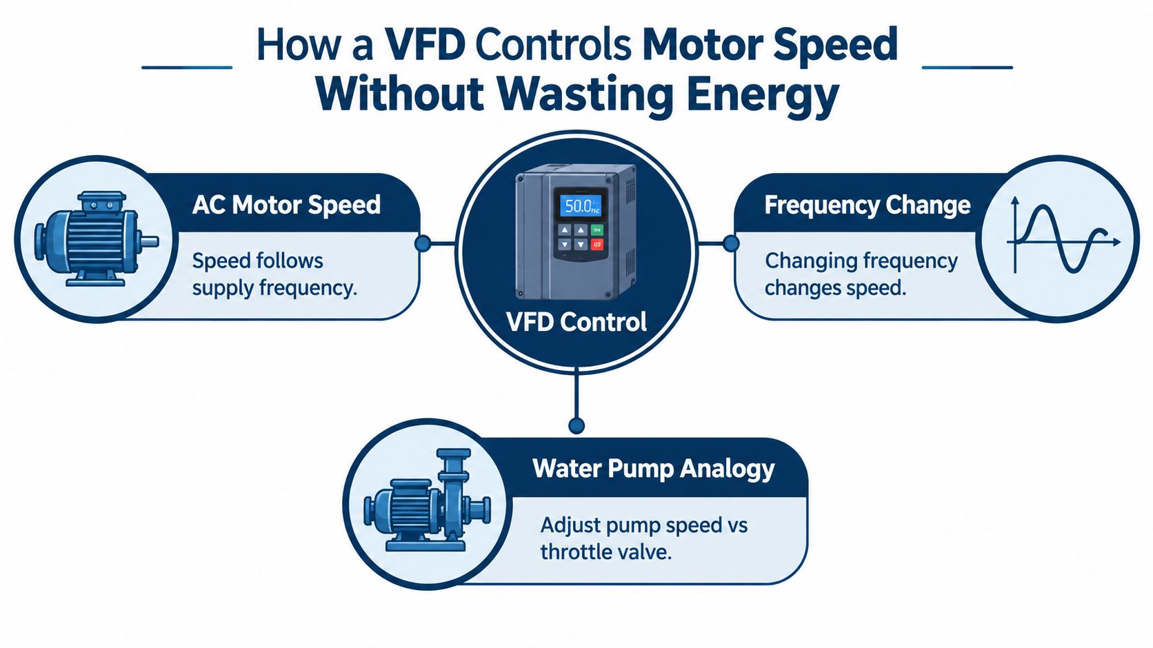
The core idea is simple. AC motor speed follows electrical frequency. If you change the frequency feeding the motor, you change the motor's speed.
Most confusion starts because people think the drive is “adding power” or “forcing torque” in some mysterious way. It isn't. In the most basic sense, it's changing the pace of the electrical waveform that tells the motor's magnetic field how fast to rotate.
Start with the process, not the electronics
Think about two ways to reduce water flow from a pump:
- Keep the pump at full speed and close a valve.
- Slow the pump so it only makes the flow you want.
The first method wastes energy because the motor still runs at full speed. The second method often saves energy because the pump does less work.
That's why VFDs fit variable-demand systems so well. They don't fight the process with a restriction device. They let the prime mover match the process.
Core principle: On an AC motor, changing frequency changes speed. On a variable-torque load like many pumps and fans, reducing speed can cut power demand far more effectively than throttling flow.
What frequency means in practice
Frequency is the rate at which the AC waveform repeats. Utility power arrives at a fixed frequency. A standard motor connected directly to the line tends to run near the speed associated with that fixed frequency.
A VFD breaks that fixed relationship. It supplies its own adjustable output, so the motor no longer has to run at just one speed.
Voltage matters too. If the drive lowers frequency, it also has to manage voltage so the motor's magnetic condition stays in a workable range. If you only changed frequency and ignored voltage, the motor's torque behavior and heating would become a problem.
Where people oversimplify
“VFD explained” articles often stop at “it changes speed and saves energy.” That's only true when the load benefits from speed reduction. A fan, pump, or blower usually does. A conveyor may benefit more from smoother control than from dramatic energy reduction.
If you want to compare common control approaches after the basics, this overview of VFD control methods is useful because it frames how different drive strategies change motor behavior in the field.
The practical takeaway
When you see a motor feeding a process with changing demand, ask one question first: Is the system controlling output by speed or by waste?
If the answer is “by waste,” a VFD may be the cleaner solution.
Inside the Drive How AC Becomes DC and Back to Controlled AC
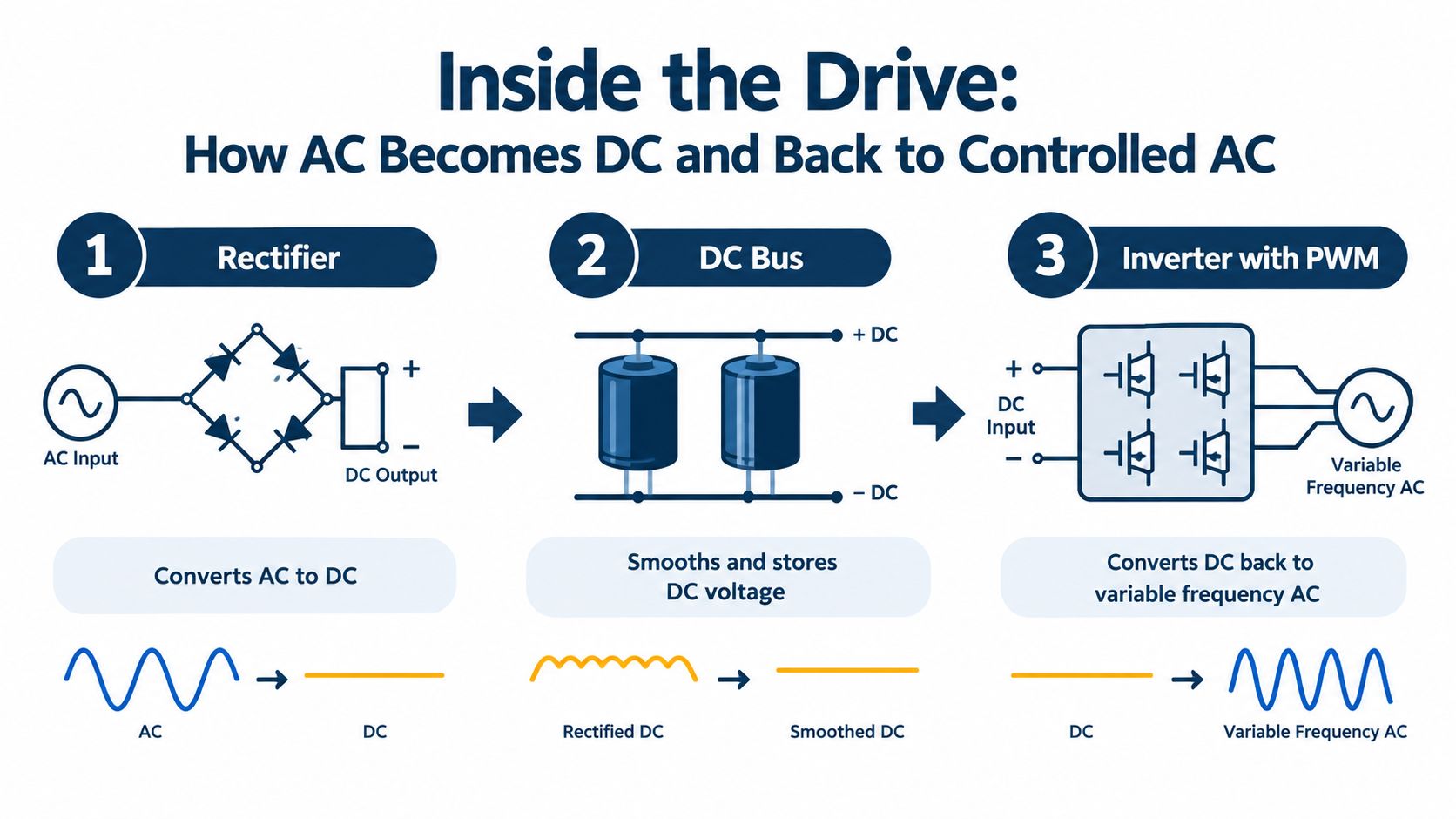
Open the cabinet mentally and follow the power path. A VFD doesn't “dial down voltage” the way some people imagine. It performs a controlled conversion in stages.
The sequence is easy to remember: AC in, DC inside, controlled AC out.
Stage one the rectifier
Incoming AC power first enters the rectifier section. Its job is to convert AC into DC.
Why do that? Because DC is easier to shape and control electronically before rebuilding it into a new AC output. Think of this as taking raw supply power and making it suitable for precision control.
Stage two the DC bus
After rectification, the drive stores and smooths energy on the DC bus. This part usually includes capacitive energy storage and associated components that reduce ripple and support the inverter section.
The DC bus is the drive's internal reservoir. It separates what's coming from the supply side from what's being sent to the motor side.
Stage three the inverter
Now comes the part many people mean when they casually say “inverter.” The inverter section switches the DC bus voltage rapidly to create a new AC output for the motor.
That output is not a pure utility-style sine wave made directly by analog means. The drive creates it by fast electronic switching. This method is commonly called PWM, or pulse width modulation.
Here's the practical picture. The drive switches power devices on and off very quickly. By controlling the timing of those pulses, it produces the fundamental voltage and frequency the motor responds to.
Why PWM matters to the motor
The motor doesn't “see” a perfectly smooth waveform at its terminals. It sees a train of rapid voltage pulses. Because the motor windings are inductive, the current becomes much smoother than the raw pulse train suggests. That's why the motor can run normally on a PWM output when the system is properly applied.
But this is also where hidden side effects begin. Fast switching gives control flexibility, yet it also introduces electrical stress that can affect cables, insulation, bearings, and electromagnetic behavior.
The drive's output can control speed very well, but it also changes the electrical environment around the motor. Good operation depends on both control quality and installation quality.
Voltage and frequency must move together
At lower speeds, the drive generally reduces voltage along with frequency. That keeps the motor's magnetic condition from drifting into a zone that creates excess heating or weak torque.
Above the motor's normal base operating point, frequency can continue upward in some applications, but voltage can't keep rising indefinitely. That changes available torque behavior. The practical lesson is simple: don't assume “more Hz” means “same torque, just faster.”
Carrier frequency and motor stress
Another term that confuses people is carrier frequency. This is the rapid switching rate used to build the PWM pattern. It is not the same thing as the motor's fundamental running frequency.
Technical guidance on harmonic mitigation notes that higher carrier frequencies can increase motor stress, and that carrier frequencies above 5 kHz raise the risk of bearing damage. The same guidance recommends keeping switching frequency around 2 to 5 kHz when motor protection is a concern (technical guidance on harmonics and switching frequency effects).
That's a classic engineering tradeoff. Higher carrier frequency can help with smoothness and audible noise in some situations, but it can also increase electrical stress. You don't set it by habit. You set it with the motor, cable, and application in mind.
Real Savings Versus Hidden Costs Harmonics and Power Quality
A good VFD application can save real energy. A careless one can create electrical side effects that people don't budget for until nuisance trips start showing up.
That's why “VFD explained” needs more than a speed-control story. It needs a system story.
Savings depend on the load profile
In high-run-hour pump and fan duty, typical savings are often reported in the 20% to 50% range when speed control replaces wasteful restriction (industrial VFD energy savings guidance). But broader market commentary tied to DOE-style analysis points out that VFDs often reduce energy use by 5% to 15%, while reported savings can range from 20% to 65% depending on application and duty cycle.
Those ranges aren't contradictory. They're describing different realities.
A cooling tower fan with long operating hours and changing demand is one thing. A conveyor with mostly constant load is another. The drive can still improve control on both, but the energy result won't look the same.
Harmonics are the hidden system cost
On the supply side, a VFD is a nonlinear load. That means it doesn't draw current in a smooth sinusoidal way. Instead, it injects harmonic current back into the electrical system.
Technical guidance commonly identifies characteristic distortion orders such as the 5th, 7th, 11th, 13th, and 17th harmonics (harmonic mitigation guidance for AC drives).
Why should a plant team care? Because harmonics can affect more than the drive itself. They can influence transformers, cables, filters, and the stability of other connected equipment. In a facility with a few small drives and a stiff supply, the effect may be manageable. In a plant with many drives or a weaker utility feed, it becomes a design issue.
When VFD savings outweigh power quality costs
| Application Profile | Expected Savings Range | Harmonic Risk and Mitigation Need |
|---|---|---|
| High-run-hour centrifugal pump or fan with changing demand | Often strong. Typical industrial guidance commonly reports 20% to 50% in suitable duty | Usually manageable, but review the plant supply if many drives share the same bus |
| Mixed-duty process load with variable operation | Often moderate. Some analyses describe more typical savings around 5% to 15% depending on duty cycle | Moderate review needed because ROI can be partly offset by filtering or power quality work |
| Plant with many drives on a constrained electrical system | Savings may still exist, but they must be verified after commissioning | Higher concern. Harmonic study, reactor or filter selection, and measurement after startup become more important |
| Constant-speed process where speed rarely changes | Energy case may be weak | Harmonic burden may outweigh the control benefit unless another process reason justifies the drive |
Don't assume the drive's purchase price is the whole project cost. The electrical system may also need reactors, filters, cable review, and post-commissioning measurement.
What experienced teams verify
Before calling a VFD project “successful,” a careful team checks:
- Actual operating profile: How many hours does the machine spend below base speed?
- Control method: Is the process really variable, or just occasionally adjusted?
- Electrical context: How many other drives share the same bus?
- Commissioning proof: Did measured power and process behavior match the estimate?
That last point matters. Estimated savings belong to proposals. Measured savings belong to operations.
Where VFDs Deliver Value Across Industrial Applications
The easiest way to understand drive value is to walk the plant.
One line uses a VFD for clear energy savings. Another uses it mainly for process stability. A third uses it because mechanical shock from fixed-speed starts is causing trouble.
Pumps and fans are the obvious wins
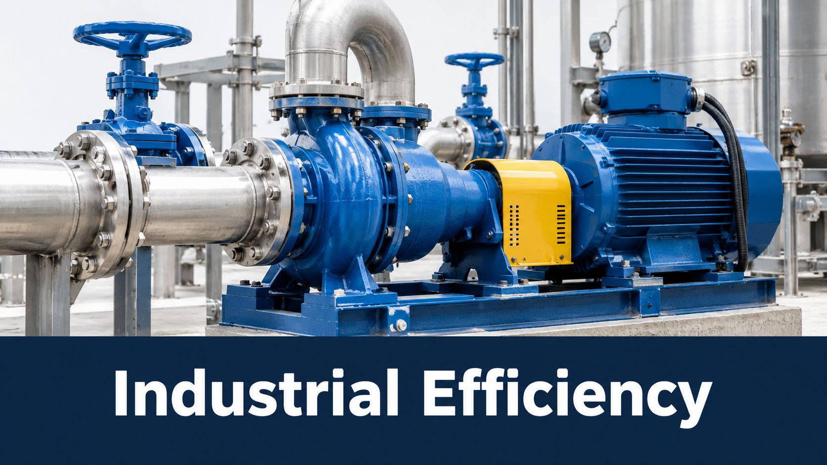
Pumps and fans are where many teams first fall in love with drives. The reason is practical, not fashionable. These loads often spend long periods away from full demand.
A chilled-water pump doesn't need the same flow in every operating condition. A process exhaust fan doesn't always need maximum airflow. In both cases, slowing the machine can be more sensible than forcing full-speed output through a control valve or damper.
Conveyors and material handling need control more than theory
A conveyor tells a different story. You may not get the same kind of dramatic energy reduction you see on centrifugal duties, but you often get better starts, smoother speed changes, and less product upset.
On a packaging or bulk-handling line, that can matter more than power reduction alone. If the process needs controlled acceleration and repeatable speed, a VFD earns its keep through stability and handling quality.
Compressors and process machinery need judgment
Compressors can benefit, but they need application-specific thinking. Some operate well with speed control. Others depend heavily on process constraints, turndown limits, and machine design.
The same is true in heavy process industries such as steel, chemicals, utilities, and HVAC infrastructure. In one service, the drive's value comes from energy management. In another, it comes from precise speed coordination. In a third, it comes from reducing abrupt starts that upset shafts, couplings, or fluid systems.
Why lifecycle thinking matters here
This isn't a small niche anymore. Historical market data from one research report shows U.S. VFD unit sales rising from 220,000 units in 1993 to an estimated 640,000 units in 1998, an increase of 420,000 units and roughly 191% growth over that period.
That historical growth helps explain a maintenance reality many plants now face. A lot of drives were installed years ago. Many are no longer “new technology.” They're part of the aging installed base, and that shifts the question from “Should we use a drive?” to “How do we keep this one reliable?”
In mature plants, the important VFD conversation often isn't selection. It's lifecycle support, spare-parts compatibility, and when to repair instead of replace.
Why Drives Fail and How Lifecycle Care Prevents Downtime
Most drives don't fail because frequency control is a bad idea. They fail because electronics live in real industrial environments, and real industrial environments are hard on electronics.
Dust enters cabinets. Heat bakes components. Fans slow down. Capacitors age. Loose power connections run warmer than they should. Output conditions punish bearings and insulation when the package around the drive isn't right.
The slow failure modes that matter most
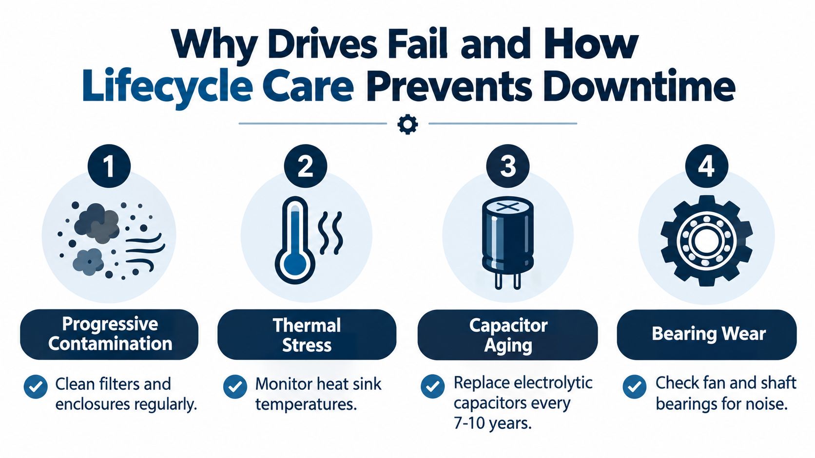
A lot of drive damage is progressive, not dramatic.
- Contamination: Dust, conductive debris, salinity, and airborne process material can settle on boards, heat sinks, and terminals.
- Thermal aging: Repeated high internal temperatures shorten component life and accelerate insulation and capacitor degradation.
- Cooling degradation: Fans, blocked air paths, and dirty filters slowly push internal temperatures upward.
- Bearing current effects: The electrical behavior of the drive-motor system can contribute to bearing damage if grounding and protection aren't adequate.
These aren't glamorous failure modes. They're the kind that build until a trip happens during the worst possible production window.
What a practical maintenance program looks like
Good lifecycle care starts before the first trip.
A proper commissioning process checks parameter logic, motor data, cable condition, grounding, cooling path, and operating response under load. Later, shutdown maintenance should focus on cleaning, thermal inspection, connection integrity, and aging components that no longer have much margin left.
If you need a field-oriented checklist, this guide to variable frequency drive maintenance aligns well with the kind of preventive work that avoids repeat faults.
Practical rule: Don't treat a successful reset as a solved problem. Treat it as a chance to find the condition that caused the trip before it returns under load.
This video gives a useful visual view of drive service thinking in practice.
<iframe width="100%" style="aspect-ratio: 16 / 9;" src="https://www.youtube.com/embed/rcKcfVQ3Vvo" frameborder="0" allow="autoplay; encrypted-media" allowfullscreen></iframe>When reconditioning beats replacement
Plants often jump too quickly from “faulted drive” to “replace the whole unit.” That can be the right answer, but not always.
If the core power structure is serviceable and the failure is concentrated in aging components, contamination effects, cooling issues, or replaceable subsystems, on-site reconditioning may be the better decision. That's especially true for large medium-voltage equipment where shipping risk, handling time, and outage windows create their own problems.
Market expansion supports this lifecycle view. One forecast cited in market coverage places the global VFD market at about USD 40.2 billion in 2026 and projects USD 69.4 billion by 2036, with Asia-Pacific projected at USD 11.06 billion in 2026 and growing at 5.62% annually through 2031. A growing installed base means more assets entering mid-life and late-life service.
That's where service providers focused on lifecycle work can fit. For example, DUCHENG Industrial offers multi-brand commissioning, maintenance, troubleshooting, repair, and on-site reconditioning for industrial VFD assets. In practical terms, that kind of support helps plants decide whether to clean and restore, repair at component level, recondition on site, or move to planned replacement.
Signals that should trigger a deeper decision
Don't wait for catastrophic failure. Escalate your review when you see patterns like these:
- Recurring nuisance trips: The reset works, but the event repeats under similar load or ambient conditions.
- Thermal alarms in hot seasons: This often points to cooling-path problems or component aging, not just weather.
- Visible contamination inside cabinets: Especially in dusty, saline, or carbon-laden environments.
- Parts uncertainty: If no one is sure the spare module, fan, board, or exchange unit is compatible, stop and verify before restart.
Key Takeaways for Reliable VFD Operation From Start Up to Renewal
A clear VFD explained summary should leave you with a practical way to think, not just a definition to repeat.
A VFD controls motor speed by converting incoming AC to DC and then rebuilding a controlled AC output for the motor. That basic idea is simple. The engineering value comes from how well the drive matches motor speed to process demand.
The decision framework that works in plants
Use a VFD confidently when the process has variable demand and speed control removes waste or improves control quality. Be more cautious when speed hardly changes, because the benefit may be operational rather than strongly energy-related.
Then check the hidden side of the ledger. Drives can save energy, but they can also add harmonic burden, carrier-frequency-related motor stress, and lifecycle maintenance requirements. The right question isn't “Do drives save energy?” It's “Does this whole drive-motor-system improve this process over its service life?”
A short lifecycle checklist
Before startup or restart, verify these points:
- Application fit: Is the load variable, or are you adding complexity without enough process benefit?
- Electrical fit: Has the plant considered harmonics, grounding, cabling, and motor suitability?
- Thermal fit: Are enclosure conditions, cooling paths, and ambient conditions under control?
- Maintenance fit: Is there a plan for shutdown inspection, cleaning, aging components, and spare-parts compatibility?
- Renewal fit: If the drive is older, would repair, reconditioning, or subsystem renewal make more sense than immediate full replacement?
A reliable VFD program treats commissioning, troubleshooting, maintenance, and renewal as one connected lifecycle, not separate jobs handed between departments.
That mindset is what keeps drives from becoming mysterious trip boxes. Once you understand the chain of cause and effect, you can talk about them clearly with operations, maintenance, procurement, and service teams, and you can make better calls when the next alarm appears.
DUCHENG Industrial supports the full VFD lifecycle, including commissioning support, preventive maintenance, troubleshooting, repair, and on-site reconditioning for industrial drive systems. If your plant is trying to reduce repeat trips, extend drive life, or decide whether an aging unit should be repaired or renewed, visit DUCHENG Industrial to review its lifecycle service approach.