
Electrical commissioning step by step: pre-start checks, insulation tests, staged energization, ramp-up, acceptance criteria and handover records for VFDs.
A drive that starts on the first press of the button proves very little. The test that matters arrives years later, at 2 a.m., when the same drive trips and the technician on shift has twenty minutes to decide whether to reset it, swap a board, or shut the line down. Everything that makes that decision fast or slow was settled during commissioning: whether the parameter set matches the motor, whether the trip was ever witnessed, whether anyone can find the as-left file without phoning the engineer who built it.
Commissioning quality should be judged by fault-isolation speed years later, not by a clean first start. That reframes the whole job. The deliverable isn't a running motor. It's a baseline a stranger can read, plus a parameter backup that has been restored once and proven to work. Get those two things right and the start is usually uneventful anyway.
Table of Contents
- Commissioning Sequence and Hold Points at a Glance
- Pre-Commissioning Checks Before Power Reaches the Drive
- Insulation and Grounding Tests Before Energization
- How to Energize and Ramp Up the Drive Safely
- Functional, Protection and Load Tests That Prove Operation
- Network, Firmware and Access Control Before Handover
- Handover Records, Acceptance Criteria and Sign-Off
Commissioning Sequence and Hold Points at a Glance
Commissioning is the witnessed proof that an installed system meets its design intent. Acceptance testing establishes safety for energization and records baseline measurements. Commissioning goes further: it verifies that the complete system performs against the owner's requirements and design basis. The InterNational Electrical Testing Association has maintained separate requirements for electrical testing since its founding in 1972. The distinction matters on a VFD lineup, where a drive can pass a bench test yet fail its process duty.
Use this sequence as a set of hold points. Do not advance until the current phase is complete and its evidence is recorded.
| Phase | What Is Verified | Hold Point to Pass |
|---|---|---|
| Document review | Single-line diagram, motor data, drive parameters, protection settings, cable schedule, grounding design, interlock logic | Conflicts closed and documents approved |
| Visual and mechanical inspection | Enclosure, clearances, ventilation, torque marks, shielding, bonding, free rotation | Punch-list items resolved or accepted in writing |
| De-energized testing | Continuity, insulation resistance, polarity, protective conductor effectiveness | Results within reference values and recorded with instrument IDs |
| Controlled energization | Incoming supply, DC-link precharge, control power, communications | No unexplained alarms or precharge faults |
| Functional and protection testing | Trips, STO, emergency stop, interlocks, permissives, restart after power loss | Each safety function witnessed and repeated in local and remote mode |
| Load proving | Voltage, current, frequency, motor temperature and process response at defined points | Stable readings within motor and drive ratings |
| Handover documentation | As-left parameters, backups, test sheets, training records, signed results | Acceptance package complete and signed by the plant owner |
Treat every row as a gate. Grounding defects, conflicting nameplate data, insulation results below reference, missing protection settings, or unexplained DC-bus behavior stop progress. Record the defect and its disposition before resuming. Do not leave an unresolved issue with a note to monitor it.
The sequence matters: inspect first, then test, and record the results. The IEC 60364-6 verification framework sets out that order. Energizing before inspection leaves the crew without a sound record of the system's condition at the start of testing.
Document review often holds up the schedule. A nameplate may change during construction, a drive may arrive with a default motor group, or interlock logic may still be under review. Close those conflicts before load proving, then have the witness initial and date each cleared gate. The completed records should let a future technician trace what was tested, what passed, and which parameter set was left in service.
Pre-Commissioning Checks Before Power Reaches the Drive
A wrong motor connection can turn a routine start-up into an avoidable trip. Before testing, match the motor nameplate to the drive's motor group: rated voltage, current, frequency, power, service factor, and star or delta connection. A mismatch in rated current can produce an overcurrent trip as soon as the motor takes load.
Check the installation against its drawings while the equipment is still de-energized:
- Trace the cable routes. Confirm power, control, and feedback cables follow the specified routes. Check shield termination, glands, and clamps against the design.
- Inspect the enclosure. Check access clearances, ventilation path, fan orientation, airflow direction, filters, and torque-marked terminations. A blocked cooling path or loose termination can cause problems after the drive enters service.
- Check control wiring. Compare the STO loop, emergency-stop circuit, permissives, and bypass circuits with the approved drawing. Confirm the STO channels match the design and remove any temporary transit jumpers.
- Turn the shaft by hand. With the load uncoupled, check for free rotation, rubbing, or binding. Confirm the direction mark matches the process requirement.
A skipped nameplate check can send the crew looking for a drive fault when the problem is an incorrect motor setting. Record each check and its result so the next technician can identify what was confirmed, rather than repeat the inspection from scratch.
Inspection comes first because the verification sequence requires it. Keep a sign-off sheet for these checks and have the supervisor witness completion. For a broader look at drive components and enclosure arrangements, see the variable frequency drive unit overview.
Insulation and Grounding Tests Before Energization
A damaged cable or a missing bond costs a few hours when you find it de-energized. Found after energization, it can take out the drive's power stage, and the diagnosis gets harder because now there are two faults. That's the entire argument for doing this work first, with the drive electronics isolated or disconnected according to the drive manual.
| Test | Method | Reference Value |
|---|---|---|
| Insulation resistance, 230/400 V power circuits | Insulation tester at 500 V DC, drive disconnected | 1 MΩ minimum |
| Insulation resistance, SELV or PELV circuits | Insulation tester at 250 V DC | 0.5 MΩ minimum |
| Motor winding insulation | Insulation tester at 1 kV DC for 60 s, motor disconnected from drive | 100 MΩ or higher when dry; below 5 MΩ, dry out and retest |
| Protective conductor continuity | Low-resistance ohmmeter, measured at both ends | Within design calculation; no open circuit |
| Motor cable shield and bonding | Continuity check at both ends per grounding design | Bonded as designed; no floating shield |
| Phase sequence | Phase rotation meter at drive input | Matches drive input design |
Test the power cable and the motor separately. Log the ambient temperature, humidity, test voltage, duration and instrument ID next to every reading, because insulation resistance moves with temperature and a bare number without conditions is unusable later.
How to read a result that fails
A low winding reading on all three phases usually means moisture or contamination, not a failed winding. Dry the motor, clean the terminal box, retest. One phase low against the other two is a genuine winding problem or a cable fault, so split the cable from the motor and retest to find which.
Continuity that disagrees with the design calculation almost always traces to a loose bonding conductor, a missing clamp, or paint and powder coat under a gland plate. Phase sequence that's wrong means two leads swapped at the drive input or at the upstream isolator, and it's worth confirming before you spend an afternoon in the parameter list.
Record, don't just pass. A reading of 250 MΩ written beside the instrument ID, the ambient temperature and the date is worth more than a tick box, because it's the only thing that lets a technician three years from now decide whether 180 MΩ is a decline or normal scatter.
Those readings are the first data points of a trend line that runs for the life of the asset. Store them where maintenance can reach them, not in a closeout folder on someone's laptop.
How to Energize and Ramp Up the Drive Safely
Energization is staged for a reason. Each stage isolates a different failure mode, so when something goes wrong you know which half of the system it came from. Keep the meter and the logbook in the same hand.

- Energize the incoming switchgear with the motor output disconnected. Confirm the DC-link precharge completes, the display stabilizes, and no alarm appears. Precharge behavior you can't explain is a stop, not a curiosity.
- Apply control power and check the interfaces. Communications up, parameters reading back as written, no stored faults, keypad and remote control both responsive.
- Prove the STO and emergency-stop inhibit. With the drive enabled, activate STO and confirm the drive refuses to run. Repeat with the emergency stop. Release each, confirm the drive is ready again but does not start on its own.
- Close the output with the load uncoupled and run at low frequency. 5 Hz is enough to confirm phase sequence, direction, current feedback and that nothing is rubbing. Reverse rotation here costs minutes; discovering it on a loaded screw conveyor costs a day.
- Step up through 25, 50, 75 and 100 percent of rated frequency. Hold at each step, checking current, vibration, drive temperature and motor noise. Speed reference and encoder or sensor scaling get verified at this point, because a scaled wrong reading looks perfect at standstill.
- Tighten the ramps to design values only after current and temperature are stable. Conservative starting ramps of 10 to 20 seconds for acceleration and deceleration give the drive and the load room to reveal a mechanical problem at part speed instead of at full current.
Ramp times are a diagnostic, not a preference. Long ramps are how you hear a bearing or see a current swing before the process is at full rate.
Reversed rotation is the classic. Most centrifugal pumps tolerate a few seconds backwards, but a fan with a non-contact seal, a screw compressor or a positive-displacement pump may not. Check direction at 5 Hz, every time, even when the electrician swears the phasing is right.
Functional, Protection and Load Tests That Prove Operation
Under production pressure, the common shortcut is a bypassed test. A trip gets jumped to restart the line, factory parameters are accepted because the motor turns, or restart behavior after a power dip goes unchecked. Those shortcuts leave gaps in the baseline, and later troubleshooting starts without a reliable record of how the drive was configured and tested.
NFPA's commissioning definition includes verifying and documenting component- and system-level requirements, planning tests and operational tune-ups, and recording baseline information for operation and maintenance. The NFPA 70B supporting statements also connect preventive maintenance, testing methods, intervals and documentation with reliability and business-risk reduction.
Build a test matrix that traces each safety function and process permissive from the field device through PLC logic to the drive response, alarm and reset. Record the expected response, measured result and witness for each test.
- Repeat each critical trip in local and remote mode. Record the trip threshold, delay and reset condition. If a high-pressure trip works locally but not from the control room, check the wiring and signal mapping before handover.
- Simulate a power dip. Confirm the drive does not restart unexpectedly when supply returns. Record the approved restart procedure and verify the drive follows it.
- Test interlocks, control-system speed reference and local-to-remote transfer. Confirm the reference and feedback values remain correct through the transfer, and that permissives do not produce an unintended run command.
- Prove the load at three defined operating points. Record input voltage and current, output current, frequency, motor temperature, process response and relevant harmonics. Include the fault history for the test period. A drive can appear stable at partial load and still show a problem at full rate.
- Save readings as a usable baseline. Record the value, operating point and instrument used. “Trip OK” gives a future technician little to work with; a measured result helps isolate changes from the original condition.
The tested parameter backup and handover baseline are the long-term deliverables. Keep them with the test matrix so a technician can compare the drive's present behavior with its commissioned state, rather than rebuilding the diagnosis from memory.
Network, Firmware and Access Control Before Handover
A drive can start correctly and still leave the next technician with no usable fault history. The network record, access settings and tested parameter backup are the baseline that makes later diagnosis faster.
Assign an owner for credentials, firmware approval and remote access. Record each drive's IP address, firmware version and access list against the as-built network diagram. Disable default passwords and unused services, and route remote access through a controlled path with logged sessions.
Kaspersky recorded 118 publicly confirmed industrial-cybersecurity incidents in Q1 2025 and 135 in Q2 2025, including attacks affecting manufacturing organizations, according to its ICS CERT incident overview. Treat access control as part of commissioning, not a setting to leave for later.
Save a parameter backup with its firmware version, then confirm it can be restored. Record the remote-stop test result, but keep network commands and safety functions distinct: a remote stop is not a substitute for a hardwired safety function.
If the drive uses a serial link, check the physical-layer details against these RS-485 RTU Modbus wiring notes. A clear network and parameter baseline lets a technician trace whether a later fault began in the drive, its configuration or the interface.
Handover Records, Acceptance Criteria and Sign-Off
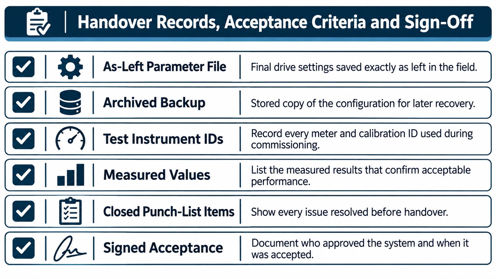
The handover package is a diagnostic tool that happens to be delivered at the end of a project. A reviewer should be able to check it without reading the commissioning file, which means each item needs evidence and a pass condition written down.
| Acceptance Criterion | Evidence Required | Pass Condition |
|---|---|---|
| Parameter set | As-left file plus archived backup | Matches commissioning record and a restore has been tested |
| Insulation and continuity | Signed test sheet with instrument IDs | Meets reference values in the insulation table |
| Protection trips | Witnessed test log per safety function | Each trip operates at its set point within design tolerance |
| Load proof | Voltage, current, frequency and temperature at three operating points | Stable and within rated limits |
| Network and firmware | IP addresses, firmware versions, access list | Documented and matching the as-built configuration |
| Punch list | Closed items with sign-off | No open no-go items |
| Operator training | Attendance and competence records | Signed off by the plant owner |
Challenge every row before you accept it
A backup counts only after a restore has been run on a spare unit or in a controlled test with the motor isolated. An unopened file is a hope, not a backup, and firmware differences between the saved file and the installed drive are exactly where restores fail.
Load proof needs readings at three operating points, not a single "runs fine". The insulation sheet needs instrument IDs so a reviewer can see which meter produced which number. The network and firmware record has to match the as-built configuration, because a firmware change made during commissioning and never written down turns the backup into a liability.
The test of a good package: hand it to a technician who has never seen this drive and time how long it takes them to find the parameter file, the insulation values and the network settings. Under an hour is a pass.
That's the honest benchmark for electrical commissioning. Not the smooth first start in the photographs, but the speed and repeatability of the next fault isolation.
The go/no-go decision for this week
Any open no-go item blocks sign-off. It's that simple, and it's the rule most often bent when the plant wants the line back. A hold point passes only when its evidence sits in the package, signed and dated. Work that isn't documented didn't happen.
Bring in a specialist for three situations: a production-critical restart where a failed start has real cost, the first energization of a large drive, or a multi-brand lineup where the configuration can't be confirmed from documents. Commissioning deliverables on that kind of support include field inspection records, start-up records, findings with recommended actions, parameter and status confirmations, and completion notes, which is exactly the evidence the acceptance table above asks for. Whether a particular brand, model and voltage class can be covered is confirmed per request from the equipment details the owner supplies, so send the nameplate data early.
If you're raising a service request, the photos that save a day are the nameplate shot straight on, the fault display before anyone resets it, and one wider shot of the installation. Those three images tell an engineer more than a paragraph of description.
So the decision this week is binary. Either close the open hold points and complete the evidence, or schedule the witnessed tests that close them. There's no third option where the drive is "basically commissioned", because the technician at 2 a.m. in three years will be reading whatever you left behind.
DUCHENG Industrial commissions, maintains and repairs multi-brand VFD systems across China and Southeast Asia, and each on-site visit closes with the records described here: inspection findings, parameter and status confirmations, and a handover note a technician can work from without calling anyone. If you're planning a start-up that has to stay diagnosable for the next five years, or you're holding a drive that tripped and won't tell you why, send the nameplate details, the fault display photo and a wide shot of the installation. Start the conversation at DUCHENG Industrial.