
Electrical Equipment Repair. Compare on-site repair and workshop VFD restoration to cut downtime. See diagnostic steps, reconditioning methods, spare parts
On-site diagnosis and reconditioning should be the default first choice for medium- and high-voltage drives, with workshop repair reserved for component-level bench work or subsystem modernization. That approach matters because manufacturing machinery maintenance is associated with approximately $222.0 billion in annual cost and losses, while maintenance strategy strongly affects downtime and defects (NIST data).
The alarm appears during a production run. A variable frequency drive trips on overcurrent, the motor coasts to a stop, and the control room asks for the fastest possible answer: reset it, replace the power module, or send the cabinet away. That pressure is understandable, but the failed component is often only the visible symptom. Heat, blocked airflow, conductive dust, unstable incoming power, reflected-wave stress, or abnormal motor loading may still be present after the repair.
Good electrical equipment repair starts with evidence. The technician needs to separate safe triage from a complete repair decision, then choose the location and depth of work that fit the fault, asset size, production window, and remaining lifecycle value.
Table of Contents
- Why Electrical Equipment Repair Decisions Are Harder Than They Look
- On-Site Repair vs Workshop Repair for Industrial Drives
- Diagnostic Methodology Before You Touch Hardware
- Workshop Deep Repair Process and Quality Checks
- MV On-Site Reconditioning to Avoid Long Shipments
- How Repair Choices Affect Downtime and Lifecycle Costs
- Spare Parts, Compatibility Checks, and Preventive Care
Why Electrical Equipment Repair Decisions Are Harder Than They Look
A drive trip doesn't tell you whether the drive failed, the motor overloaded, or the installation created the stress. A quick reset can restore production briefly, but it also erases the opportunity to capture the fault state. A component swap can bring the cabinet back online while leaving the original thermal or electrical cause untouched.

Triage is not the same as repair
During an emergency response, the first task is to establish whether the equipment can be made safe and whether the fault is repeatable. Record the alarm history, operating speed, motor load, cabinet condition, recent work, and incoming-voltage behavior before clearing anything. If the drive restarts, treat that restart as a controlled test, not proof that the problem has disappeared.
The complete repair decision comes later. It may involve cleaning and reconditioning the cabinet, testing semiconductors and capacitors, correcting cooling, validating motor parameters, checking cable conditions, or moving the unit to a workshop for deeper disassembly.
Practical rule: A failed IGBT, capacitor, fan, or control board is a repair finding. It isn't automatically the root cause.
Three routes can produce three different outcomes
A field technician may correct contamination, replace a serviceable fan, verify parameters, and complete a controlled loaded test. A workshop team may need to dismantle the drive, test assemblies individually, replace aging parts, and validate the repaired unit on a bench. A modernization project may renew a subsystem when the existing architecture has become difficult to support.
The wrong choice usually looks attractive because it focuses on the immediate invoice or the quickest reset. The right choice considers repeat-failure risk, restart quality, transport exposure, parts availability, and the value of the production window being protected.
On-Site Repair vs Workshop Repair for Industrial Drives
On-site and workshop repair solve different problems. Field work is strongest when the asset is large, difficult to remove, tightly connected to the plant, or affected by an environmental condition that must be observed in place. Workshop work is stronger when the unit needs controlled disassembly, component-level testing, assembly inspection, and repeated functional checks away from production pressure.
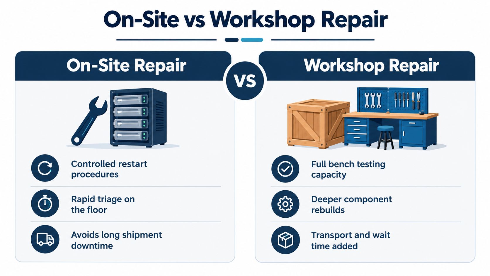
| Decision factor | On-site repair | Workshop repair |
|---|---|---|
| Downtime | Supports rapid triage and a planned controlled restart | Adds removal, shipment, queue, and return time |
| Asset size | Suited to large or medium-voltage equipment that is difficult to move | Practical for removable low-voltage drives and modules |
| Environmental evidence | Preserves the actual cabinet, cooling path, contamination, and installation conditions | Allows clean bench work, but may separate the drive from the site conditions that caused failure |
| Testing depth | Limited by site instruments, access, load availability, and safety controls | Supports deeper disassembly, component tests, reassembly, and extended functional testing |
| Transport risk | Avoids lifting, packing, vibration, and handling damage | Requires controlled packaging and documented pre-shipment condition |
| Best use | Diagnosis, reconditioning, subsystem exchange, commissioning, and controlled recovery | Deep repair, component rebuild, exchange-unit preparation, and modernization |
When the floor is the better repair location
A medium-voltage drive with fixed cabling, substantial enclosure mass, and limited standby capacity often shouldn't be shipped for a fault that can be isolated and corrected on site. Field technicians can inspect filters, fans, bus connections, cooling channels, contamination, and operating conditions where the failure occurred. They can also verify the motor, cable route, grounding, and load behavior before the restart.
That doesn't mean every field repair should be improvised. The site needs an approved isolation procedure, suitable test instruments, spare-part identification, parameter backups, and a documented restart sequence.
When a workshop earns its place
Workshop repair becomes sensible when the drive has internal damage that can't be reliably assessed in the cabinet, when several subsystems show age-related risk, or when the plant can use a verified exchange unit during the repair window. Bench testing can expose intermittent faults, confirm gate-drive behavior, inspect solder joints and bus structures, and validate repaired assemblies under controlled conditions.
The trade-off is time. Shipping a drive may reduce the technician's exposure to a difficult site, but it can extend the outage and remove the equipment from the environment that must ultimately be corrected.
Diagnostic Methodology Before You Touch Hardware
A drive can come back from repair, pass a quick restart, and still fail again on the same line because the cause was never inside the cabinet. Start with the conditions around the trip. Heat, humidity, contamination, supply instability, lubrication issues, and abnormal mechanical load often stack up and push the drive, motor, and cable system together. The U.S. Department of Energy motor maintenance brief supports treating these as connected degradation stresses rather than isolated symptoms.
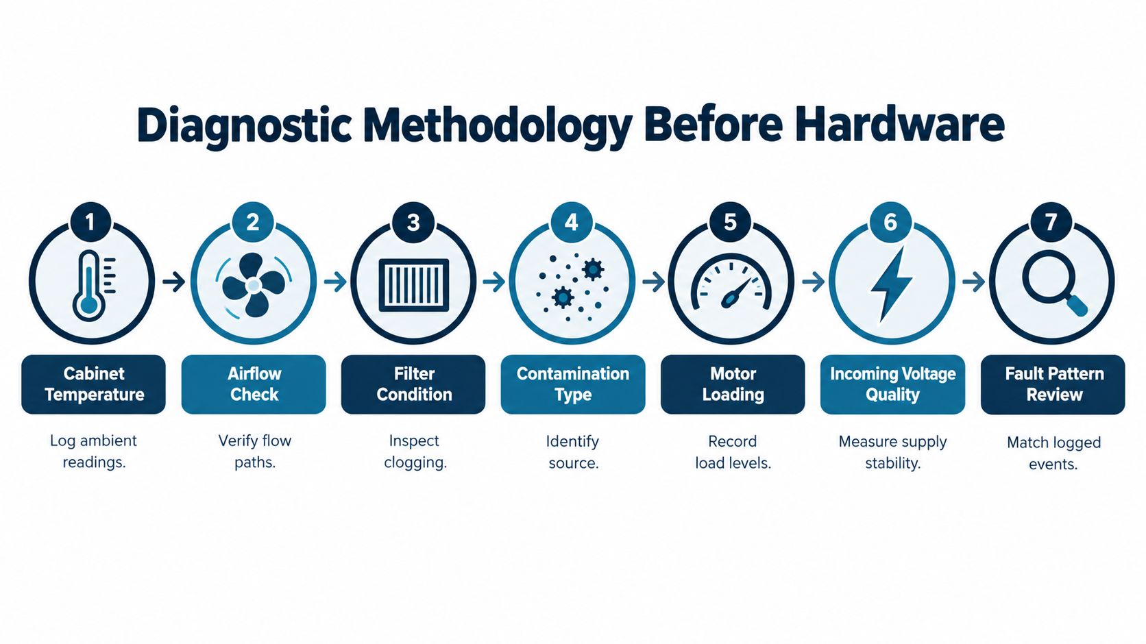
Start with the operating environment
Walk the installation before opening up hardware. Record cabinet temperature and ambient conditions. Check whether fans are moving air along the intended path, whether filters are loaded up, and whether heat is collecting around power modules or buswork. Do not clean first. Identify the contamination as found. Fine dust, carbon residue, salt, oil mist, and moisture behave differently once voltage and temperature are applied.
Then tie those observations to the operating record:
- Motor loading: Capture load level, acceleration behavior, speed range, and any recent mechanical changes.
- Incoming supply: Measure voltage, phase balance, current, and signs of transient or harmonic stress.
- Fault history: Review alarms by time, speed, load, and operating sequence, not only the latest code.
- Thermal condition: Compare hot components with similar components and record how temperatures shift under load.
- Physical condition: Inspect terminals, cooling paths, bus structures, cable entries, and any tracking or discoloration.
Separate symptom from initiating stress
Trip codes point to the protection that reacted. They do not automatically identify the part that started the problem.
An overcurrent trip may come from a failing output device, but it can also follow a jammed machine, an acceleration profile that no longer matches the load, motor damage, or cable stress. Repeated power-module failures often trace back to restricted airflow and thermal cycling. If those conditions stay in place, another repaired unit can die the same way.
Low-speed duty needs special attention. Operation below 60 Hz can require reduced torque demand or supplemental motor cooling because a self-ventilated motor moves less cooling air at reduced speed, as noted in the DOE motor brief. On the floor, that shows up as a drive that runs cleanly at higher speed but overheats during long low-speed production or hold periods.
Make power quality part of the repair decision
Bench results matter, but a no-load bench run does not reproduce every field stress. Check input voltage and current, phase balance, waveform shape, and harmonic content during representative operation. According to power-quality testing guidance, a total harmonic distortion level above 6% is a potential problem that merits investigation.
If distortion shifts with load or speed, inspect rectifier condition, line reactors or filters, capacitor-switching events, transformer impedance, and other nonlinear loads on the same bus. Keep those readings as a baseline for the next event. The repair decision may end at a board or module, but the failure mechanism often sits in the supply, motor circuit, environment, or all three together.
Workshop Deep Repair Process and Quality Checks
Workshop repair should begin with the diagnostic record, not with a box of replacement parts. The shop needs the drive identity, configuration, fault history, environmental observations, motor information, parameter backup, and the circumstances of the trip. Without that context, bench technicians may produce a functional unit that still fails when returned to the plant.
Control the disassembly
Photograph and label cables, connectors, bus links, shielding, grounding points, and parameter boards before removal. Inspect the enclosure for dust paths, moisture marks, heat discoloration, loose hardware, and evidence of arcing. The technician should document what was found before cleaning because contamination patterns often show where air movement or sealing has failed.
Bench diagnostics can then proceed by subsystem:
- Power section: Test rectifier paths, IGBTs or other switching devices, DC-bus capacitors, snubbers, and fuses.
- Control section: Check boards, gate-drive circuits, feedback interfaces, communication cards, and stored parameters.
- Cooling system: Verify fan condition, heatsink cleanliness, thermal interfaces, and airflow performance.
- Protection circuits: Confirm sensing, trip thresholds, interlocks, and fault recording.
- Insulation and connections: Test relevant insulation paths and inspect terminations before reassembly.
Test the repaired assembly, not only the replaced part
A replacement module can pass an isolated test while the gate-drive circuit, bus capacitor, feedback channel, or cooling system remains defective. Reassembly should include torque verification, connector inspection, parameter validation, and a comparison against the approved configuration.
Functional testing should progress from safe energization to control checks, then to unloaded operation and a representative loaded test when the equipment and facility allow it. Record current balance, fault behavior, temperature, speed response, braking behavior, and communication status. A unit isn't ready for dispatch just because it powers up.
Workshop standard: Every repair needs a before-and-after record, a parts trace, parameter confirmation, and a defined acceptance test.
Subsystem modernization can be more rational than a full replacement when the enclosure, power path, motor interface, and protection architecture remain serviceable. That decision still requires a compatibility review, lifecycle assessment, and confirmation that the renewed subsystem will work with the existing motor, cable, controls, cooling, and protection scheme.
MV On-Site Reconditioning to Avoid Long Shipments
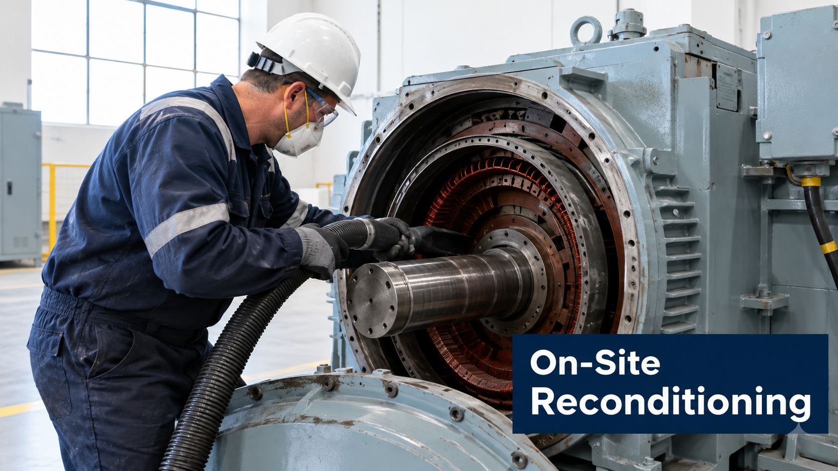
Large medium- and high-voltage drives change the logistics calculation. Removal may require lifting plans, specialist transport, disconnection of fixed cabling, and a long outage before the workshop even receives the asset. Shipping also removes the drive from the very environment that may be producing the failure, so the returned unit can face the same heat, contamination, or power-quality stress on its first day back.
Use the shutdown window as a reliability project
On-site reconditioning works best when planned around an outage rather than attempted as an improvised emergency repair. The team can isolate the drive, inspect and clean the cabinet, restore cooling paths, examine power assemblies, verify connections, test insulation where appropriate, inspect the motor circuit, and complete controlled energization in a defined sequence.
The work should produce more than a clean enclosure. It needs a condition record, photographs, thermal observations, parameter backup, test results, replaced-part details, and recommendations for the next maintenance window. This documentation gives reliability and procurement teams a defensible basis for deciding whether to retain, modernize, or replace the asset.
Keep the installation in view
The repaired drive must be checked alongside its motor and cable system. Inverter switching can create fast voltage edges, reflected-wave effects, common-mode voltage, and harmonic currents that stress motor insulation and bearings. Evidence on inverter-driven motor life reports voltage edges of roughly 2 to 10 kV/µs, and laboratory findings describe a 40% to 60% reduction in turn-to-turn life under representative PWM stress compared with sinusoidal excitation (inverter motor-life evidence).
That makes cable length, impedance, grounding, bonding, output reactors or filters, shaft-current mitigation, and motor insulation part of the reconditioning scope. A repaired inverter can be technically sound and still fail again if the connected system continues applying the original stress.
For additional context on asset-specific service considerations, see this guide to medium-voltage drive maintenance. The practical decision is simple: if removal creates more operational risk than controlled field work, recondition the asset where it operates and verify the complete system before restart.
How Repair Choices Affect Downtime and Lifecycle Costs
A low repair invoice can still be the expensive choice on the plant ledger. Replacing one failed power module may get the drive back online, but it can leave old capacitors, tired fans, weakened insulation, and aging control boards in service. A broader workshop rebuild costs more at the start, yet it can cut the chance of another stop during a high-value production run. Full modernization makes sense when support is thin, the platform is obsolete, or one more repeat failure carries too much operational risk.
The floor-level question is not only repair versus replace. It is whether the repaired unit will survive the same heat, contamination, vibration, grounding faults, and power-quality stress that damaged it in the first place.
Build a lifecycle comparison
For each option, document:
| Question | Why it changes the decision |
|---|---|
| What remains at risk? | Semiconductor, capacitor, fan, insulation, and control-board condition set the exposure after restart |
| Can parts be supported? | Obsolescence and uncertain compatibility can turn a minor fault into a long outage |
| How critical is the asset? | A standby utility drive and a production bottleneck do not justify the same risk tolerance |
| What is the restart risk? | A fast restart can trigger a second outage when parameters, cooling, interlocks, or incoming supply conditions are not verified |
| What energy impact follows? | Motor-driven equipment consumes more than 700 billion kilowatt-hours annually in U.S. industry and represents more than $30 billion in yearly electricity spending, according to the Department of Energy motor-system data |
| What does removal involve? | Shipping, lifting, disconnection, and recommissioning can outweigh the bench repair itself on a large drive |
Energy use belongs in the repair decision because poor repair scope often hides operating losses. The same DOE motor-system data shows many plants can cut motor-driven electricity use through system improvements, and that cost-effective efficiency gains are often available at facility level. If the job restores rotation but leaves poor loading, bad cooling, unstable control settings, or unresolved supply-side stress in place, the drive may run again without running well.
That is where structured diagnostics change the economics. If the DC bus was overstressed by line imbalance, if repeated trips came from a cooling path blocked by dust, or if reflected-wave stress is hitting both motor and inverter, a narrow component swap only buys time.
Don't use downtime frequency as the only scorecard
A maintenance team can report fewer events and still spend more money per event. Surveyed maintenance professionals reported that 71% viewed preventive maintenance as foundational, yet fewer than 35% spent most of their time on it. The same survey found that 31% reported increased downtime costs, while only 20% saw costs decrease (industrial maintenance survey).
That matches what happens in real plants. One trip during a low-demand shift may be manageable. The same trip during a constrained run, with operators waiting, upstream inventory building, and a restart sequence that needs verification across the line, can cost far more than the repair ticket suggests. Track production context, diagnostic time, repair time, restart checks, lost-output exposure, and return visits, not just trip count.
NIST maintenance findings also connect maintenance maturity with better operational results across manufacturing machinery. The takeaway for drive work is practical. Treat repair as a reliability decision, not as a parts transaction. If the post-repair plan does not address the environment around the drive and the power conditions feeding it, the same unit can come back from the shop healthy and fail again for the same system-level reason.
Spare Parts, Compatibility Checks, and Preventive Care
A spare part is only useful when it matches the installed architecture and the operating duty. Part numbers, revision levels, voltage class, current rating, firmware or parameter dependencies, cooling arrangement, feedback interface, and control-board compatibility all need review before dispatch. A visually similar module can create a repeat trip if its electrical characteristics or configuration don't match the original system.
Make every exchange unit traceable
The parts process should answer five questions before installation:
- What failed? Link the proposed part to the diagnostic finding, not just the alarm code.
- What does it replace? Confirm manufacturer identification, revision, rating, and interface.
- What else depends on it? Review gate drives, sensors, protection circuits, firmware, parameters, and cooling.
- How was it tested? Require pre-dispatch verification, inspection records, and functional evidence.
- What changes after installation? Record parameters, protection settings, cable conditions, and acceptance results.
This discipline matters most when the plant is under pressure. Emergency substitutions often create undocumented changes that complicate the next fault. A controlled exchange-unit program reduces that uncertainty by keeping identification, compatibility review, and test records with the asset history.
Preventive care should target the failure environment
During planned shutdowns, remove contamination using methods appropriate to the equipment and residue. Inspect thermal paths, fans, filters, terminals, bus structures, seals, cable entries, and signs of moisture or salt exposure. Thermal inspection under representative load can identify abnormal heating that a de-energized visual check won't reveal, while insulation and power-quality tests address failure modes that temperature alone can't expose.
The electrical preventive maintenance guidance is useful as a planning reference, but the work order should remain specific to the asset. Record what was cleaned, what was measured, what changed, and what still needs monitoring.
Use a simple keep, upgrade, or renew decision
Keep the drive in service when the root cause is understood, remaining subsystems are healthy, parts are supportable, and post-repair testing confirms stable operation.
Upgrade a subsystem when the cabinet and installation remain suitable but a vulnerable or obsolete assembly can be renewed with verified compatibility and documented testing.
Plan renewal when failures are recurring, critical parts are unavailable, the connected motor system is incompatible, or the residual risk is higher than the value of extending service life.
DUCHENG Industrial provides on-site diagnosis, VFD workshop repair, preventive care, and on-site reconditioning for medium- and high-voltage drives, along with spare-parts identification and compatibility checks. For a plant facing a recurring trip, start by compiling the fault history, environmental observations, power-quality readings, and asset constraints, then invite DUCHENG Industrial to assess the appropriate repair route.