
Learn what an electrical load center does, how to size it by fault current and temperature, and how it fits with VFD drive systems.
You're in the electrical room while a line is still running. A drive has tripped, the panel beside the motor control center has open breaker spaces, and someone wants another feeder landed before the shift ends. The bus amperes look fine. The empty slots look like spare capacity. They usually aren't. Fault duty and heat decide whether that electrical load center can take the load, and the code plus the manufacturer's data decide the final answer.
I would start with the available fault current on the one-line, not with a larger ampere rating. A bigger bus that can't interrupt the fault, or that runs hot enough to pull the trip curve down, fails the plant even when the nameplate current looks generous.
Table of Contents
- What an Electrical Load Center Does and Where It Sits
- Load Centers, Panelboards and Switchgear Compared
- How to Size a Load Center by Fault Current
- Heat Limits That Cause Nuisance Trips
- Connecting Load Centers to VFD Drive Systems
- Verify the Specification and Next Steps
What an Electrical Load Center Does and Where It Sits
Think of an electrical load center as a neighborhood hub. One supply comes in, and the hub splits it into labeled branches, each with its own breaker, so one fault doesn't darken the whole street.
It does three jobs, in this order. It receives the supply through a main breaker. It spreads power across the busbar. It isolates the branch that overloads or faults, and leaves the other branches in service.
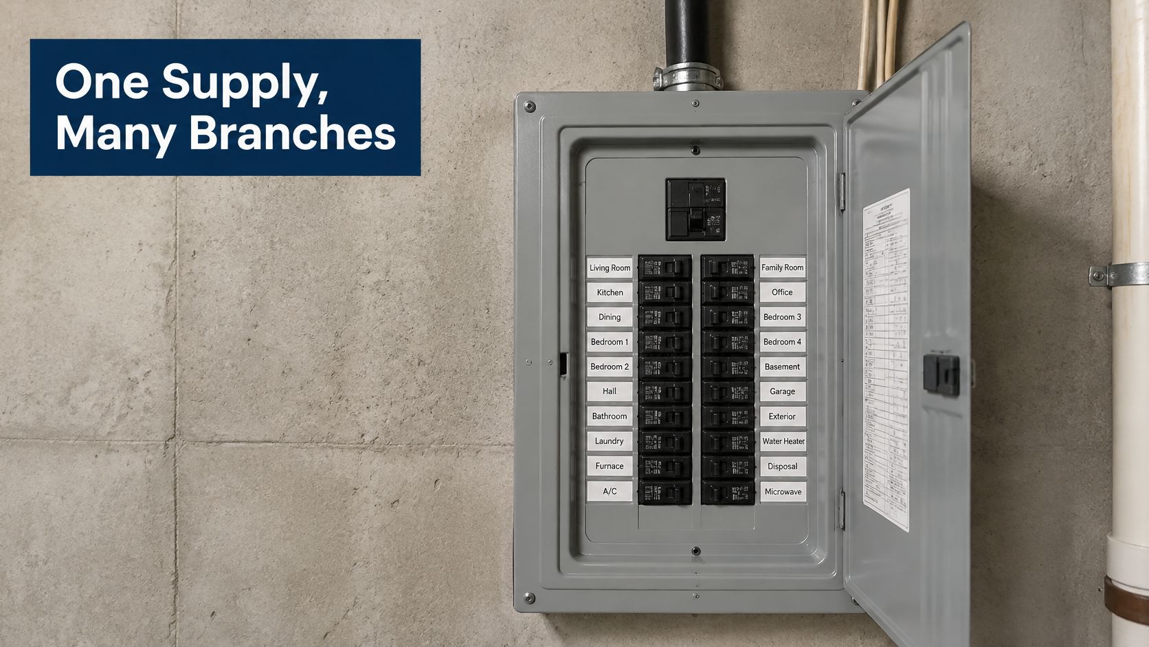
Plug-in breakers clip straight onto the busbar. That keeps the enclosure compact, the hardware inexpensive, and later circuits easy to add without a custom bus design.
In the plant chain it sits late. Power moves from the utility transformer to the main switchgear, through distribution, into the load center, and out to final circuits.
Where it belongs: In a plant, a load center normally serves auxiliary, utility, and building-service circuits. It is not the right home for large motor feeders or a bank of drives.
Load Centers, Panelboards and Switchgear Compared
Screen the assembly by class before you argue about spare spaces. Ampere rating shows how much current the bus can carry. Voltage class and fault duty decide whether that assembly is allowed at the location at all.
| Class | Typical voltage | Typical current rating | Breaker connection | Best fit |
|---|---|---|---|---|
| Electrical load center | Up to 240 V | Generally below 400 A; many conventional units up to about 225 A | Plug-in breakers on busbar | Building-service, auxiliary and small-commercial circuits |
| Industrial panelboard | Up to about 600 V | Up to about 1,200 A | Bolt-on breakers common | Plant sub-distribution with higher fault duty |
| Switchboard or switchgear | Above 600 V in many plants; medium voltage at larger sites | Often several thousand A | Fixed or draw-out breakers | Main distribution, large motor feeders and large VFDs |
Read the first two columns as a gate, not a shopping list. A 240 V building auxiliary panel can sit in a load center. A 480 V feeder for a large drive or motor starter moves up to a panelboard or switchboard, because the voltage and the fault duty have already left the load-center class.
As ABB describes panelboards, a load center is a low-voltage branch-circuit assembly used mainly in residential and small-commercial facilities. Modern load centers commonly operate at up to 240 volts and are generally rated below 400 amperes, and many conventional North American units are rated up to about 225 amperes. Industrial panelboards commonly support higher ratings, up to about 600 volts and 1,200 amperes, and may use bolt-on breakers where fault duty and protection are heavier.
Plug-in breakers suit standardized expansion in homes and small commercial work. Panelboards and switchgear use bolt-on or draw-out breakers because coordination, replacement under fault duty, and isolation of a single feeder matter more than a quick clip-on add.
For maintenance teams, the split is practical. A load center fits smaller auxiliary, utility, and building-service circuits. Motor feeders, large VFDs, and process distribution need panelboards, switchboards, or switchgear with stronger short-circuit ratings and real coordination.
Match the assembly to the highest voltage, current, and fault duty of its circuits, not to the cheapest label on the shelf.
How to Size a Load Center by Fault Current
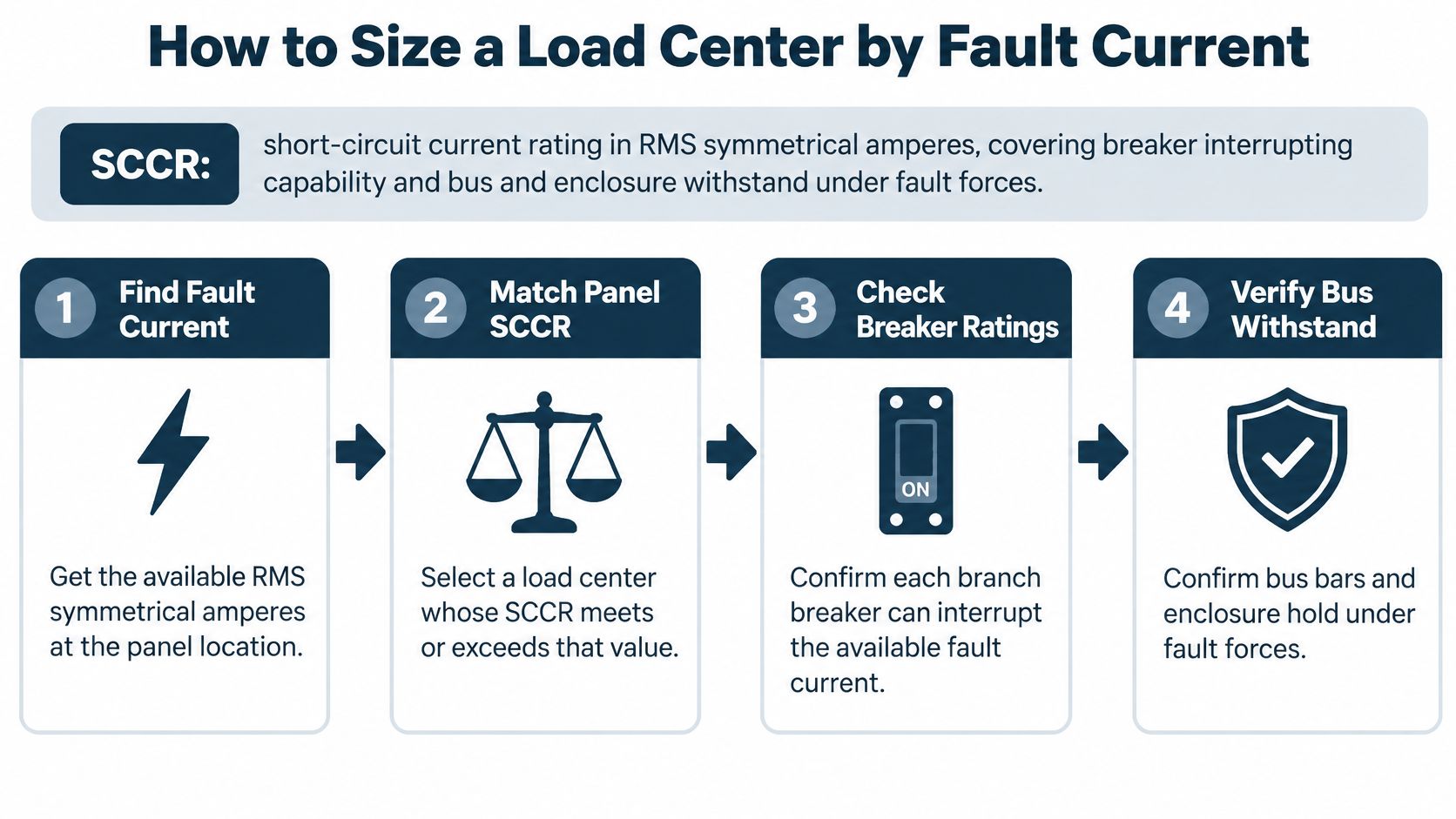
Select the electrical load center by its short-circuit current rating (SCCR) first; continuous amperes alone say nothing about whether the assembly survives a fault. As the UL panelboards guide puts it, SCCR, in RMS symmetrical amperes, covers both the interrupting capability of the overcurrent devices and the mechanical withstand of the bus and enclosure under fault magnetic forces. The marked SCCR must at least equal the available fault current at that point, and a transformer or utility upgrade can turn an acceptable panel into an underrated one without touching its normal-load rating.
Seven checks before you buy or add a circuit
- Total the load on each phase. Base it on the drive's input current at full rated load; nameplate kilowatts understate what the rectifier draws. A phase that looks light on paper can be the hot one.
- Apply the continuous-load factor your code requires. Loads that run three hours or more count as continuous. Treating them as intermittent is how a correctly sized bus ends up permanently overloaded.
- Get the available fault current at the installation point. A coordination study, or a verified calculation, has to include transformer kVA, feeder impedance, and upstream clearing time. Those three set the prospective duty the gear must survive.
- Confirm the marked SCCR meets or exceeds that value. A unit that only clears a generic floor still fails if the calculated duty at this wall runs higher.
- Confirm the main, the branch breakers, and the bus are listed as one configuration. The lowest interrupting rating in the assembly caps the whole rating, and a visually compatible breaker with a lower rating can void it. Where the duty is high enough that a molded-case device is the wrong class, look at an insulated case breaker instead of forcing a residential-style frame into the slot.
- Check bus temperature rise against the manufacturer's derating. Harmonic-rich drive loads and a fully populated enclosure both shrink the margin the nameplate implies.
- Leave fault-duty headroom for what comes next. A transformer swap, a stiffer utility service, or a larger upstream feeder all raise the available fault current. Sizing exactly to today's number means the assembly can age out before the load does.
Where the Minimum Falls Short
Published plant and facility specifications set floor ratings that rise with voltage class. Higher-voltage systems need a project study, not a copied low-voltage figure.
| Voltage class | Minimum SCCR (RMS symmetrical) | Basis for the figure | Check before accepting |
|---|---|---|---|
| 208/240 V | 10 kA | Typical floor in facility specifications | Compare with calculated available fault current |
| 480 V | 14 kA | Typical floor in facility specifications | Compare with calculated available fault current |
| Above 600 V | Set by coordination study | Project-specific | Compare with calculated available fault current |
Say the study shows 22 kA available at a 240 V load center. That assembly needs a marked SCCR of at least 22 kA, and every device in the listed configuration has to hold that rating. Install a 10 kA unit there and the breakers are being asked to interrupt more than twice their tested duty; the most likely failure mode is a device that cannot clear the fault, with the bus and enclosure absorbing forces they were never braced for. Drive input faults, feeder impedance, transformer kVA, and upstream clearing time all move the study number, and the same study shapes whether a drive can restart cleanly once the fault clears.
Heat Limits That Cause Nuisance Trips
The most common complaint is a breaker that trips on a hot afternoon at a current the schedule says is normal. The current didn't spike. The trip threshold dropped.
Breaker curves are temperature-dependent. When the enclosure or the room rises above the breaker's reference temperature, the overload trip point falls, and you have to use the manufacturer's derating, not a rule of thumb. Adjacent breakers that are all carrying load heat each other. The circuit-breaker selection guidance notes that a typical engineering example uses about a 0.8 factor when normal-current heating is significant. A bus nominally rated for a given current should not be run at that current when the panel is dense, continuously loaded, sitting in a hot electrical room, or feeding nonlinear loads.
Bus sizing is tied to UL 67 temperature-rise limits. Ventilation, how the conductors are routed, how unused space is used, and heat sources above or below the cabinet all change the margin you have. Drive harmonics add heating on top of that ambient, in neutrals, breaker poles, and bus joints.
What to measure before you change hardware
Inventory simultaneous loading by phase, not the sum of nameplates. Measure enclosure temperature and terminal temperature during peak production. Then check derating against that breaker's own tables. A generic 0.8 is a warning, not a substitute for the table.
| Symptom | Likely thermal cause | Corrective action |
|---|---|---|
| Breakers trip on hot afternoons at normal current | Enclosure or room above breaker reference temperature | Apply manufacturer derating tables and improve ventilation |
| Cluster of loaded breakers runs hot together | Mutual heating between adjacent breakers, about a 0.8 factor in one engineering example | Redistribute circuits across phases and spread the load |
| Discolored bus joints or hot terminals | Loose or overloaded connections in a hot cabinet | Measure terminal temperature at peak, re-torque and reduce load |
| VFD-fed circuits trip or run hot under nonlinear load | Harmonic heating added to ambient temperature | Separate high-loss drives, check harmonic content and upsize if needed |
| Insulation and breakers age faster than expected | Sustained high temperature | Reduce continuous loading or replace with a higher-capacity assembly |
Spend money in this order. Redistribute circuits across phases. Cut continuous loading. Improve cabinet airflow. Move high-loss equipment out of the enclosure. Replace the load center with a higher-capacity assembly only after those steps still leave no margin. The same heat that nuisance-trips a breaker also ages a thermal overload relay and the conductors it is meant to protect. Fixing the temperature slows insulation, bus-joint, and breaker aging instead of treating every trip as a defective device.
Connecting Load Centers to VFD Drive Systems
Put a true-RMS clamp meter on the input phase of a running drive and the reading usually tells a different story than the panel schedule. The rectifier front end draws current in pulses, so the RMS load on the breaker and neutral runs higher than the fundamental current the motor really turns into work. That gap is where VFD connections go wrong: the schedule says the circuit has room, and the conductors disagree.
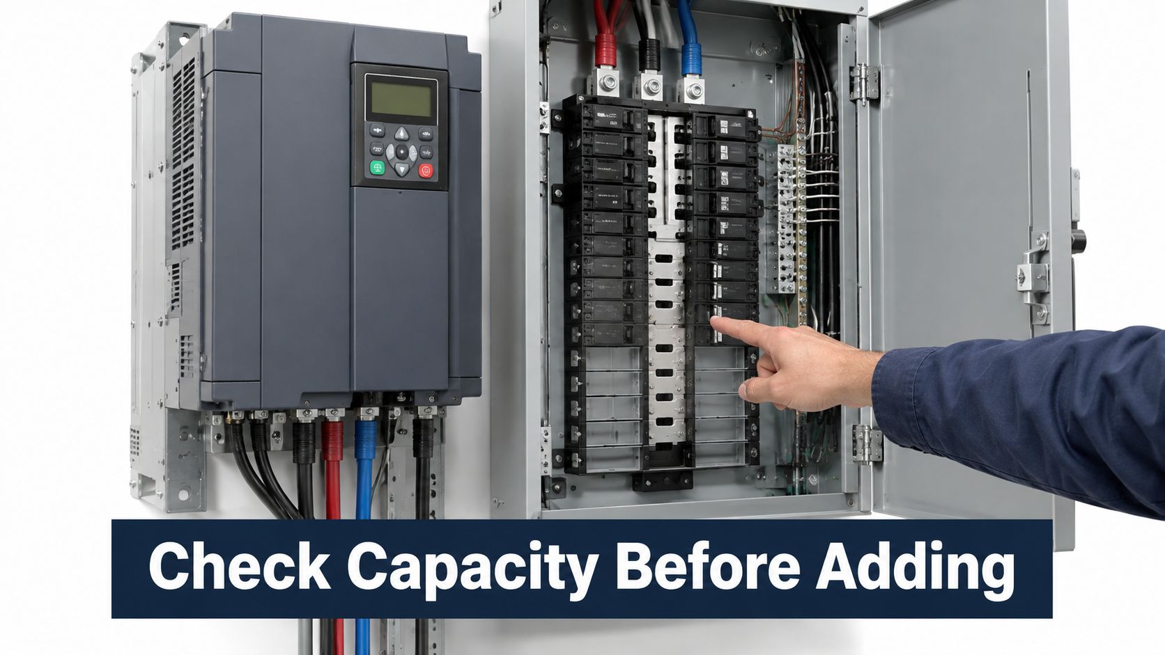
Three measurements before you add a drive
Read the rectifier input current, not the motor nameplate. The drive's rated input current is what the breaker, feeder, and neutral carry in practice. Clamp each phase at full load and compare the reading against the breaker frame and conductor ampacity, not against the kilowatt figure on the schedule.
Scan the neutral and bus joints under harmonic loading. Rectifier front ends push harmonic current through neutral conductors and bus connections that a fundamental-only load calculation never counts. A thermal image of the neutral and main lugs at peak drive loading shows whether the board is already carrying more heat than its label suggests.
Compare the measured voltage dip with the drive's ride-through spec. Every drive manual lists an undervoltage threshold and a ride-through window. Record the dip at the load center during the largest motor start or fault clearance the feeder sees, then set it against that threshold. A dip deeper or longer than the drive tolerates means a fault on restart no matter how clean the new breaker looks.
Give each large drive its own breaker and feeder. Write down the measured input current, the harmonic reading, and the dip the drive must ride through, then confirm the connected control equipment still accepts the power quality once the new circuit is on.
The IEA Electricity 2025 report identifies building, transport, and industrial electrification, along with air-conditioning and data-center growth, as major forces increasing electricity demand through 2027. The same pressure shows up inside one plant: EV charging, heat pumps, extra cooling, onsite generation, and battery storage all ask the existing board for room it may not have.
A staged plan treats every remaining stab position as conditional capacity. The board has to pass the thermal, fault, and coordination checks again at each stage before the next circuit closes.
A simple load calculation totals connected kilowatts and stops. A staged capacity plan does not energize the next circuit until the board still passes.
- Calculate connected and diversified demand for each planned load, including charging, heat pumps, cooling growth, onsite generation, and storage.
- Check the existing board for thermal margin, transformer limit, voltage drop, and fault duty before any new circuit is added.
- Test managed charging or load shedding before you commit to a service upgrade. Sometimes the deferral is real. Sometimes it only hides a transformer that is already at its limit.
- Recheck fault current and backfeed once generation or storage can energize the bus from the load side.
- Stage additions by phase and by year, with a go or no-go at each stage before anyone closes the breaker.
Someone still has to update the one-line, label the new circuit, validate settings, and confirm the drives accept the revised supply. Skip that handoff and the measurements go stale while the equipment keeps aging.
Verify the Specification and Next Steps
A higher ampere rating does not make an electrical load center safer or more future-proof. An incorrectly matched breaker, or an interrupting rating below the available fault current, leaves the installation noncompliant even when the bus looks ample. Procurement still has to write the spec as if the panel will sit beside VFDs, motor control centers, transformers, and emergency power, because that is where plant upgrades really land.
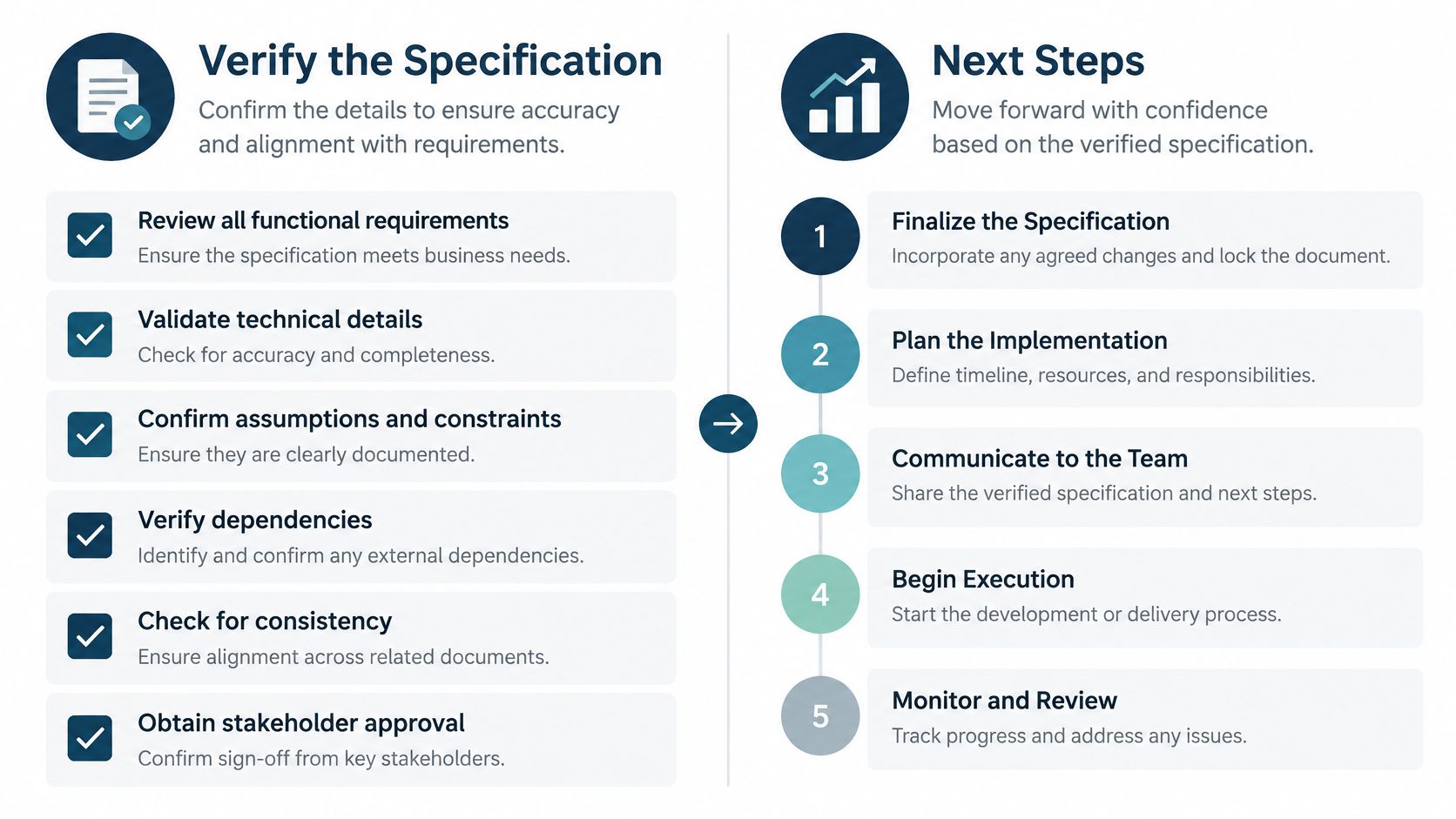
Pre-purchase checks
A public facilities specification is a useful model for what to demand on paper, not just a voltage and an ampere frame.
- Specify separate copper neutral and ground buses. Shared or mixed buses make fault tracing slower and complicate the bonding the design assumed.
- Name the standards. That specification requires compliance with NEC, NESC, NEMA, and ANSI. Write those calls into the purchase documents so a residential load center can't be substituted on price.
- Require arc-flash labels with incident energy calculated using IEEE 1584. Technicians need the hazard on the door before the cover comes off, not in a binder back in the office.
- Match the enclosure to the room. Dust, humidity, carbon black, and salinity change what "indoor" means. A clean electrical room and a process building are not the same environment.
- Confirm the drive against the assembly before you order. We confirm whether a specific brand, model, and voltage class can be serviced from the equipment details you send. Include brand, exact model code, rated power and voltage, the fault code exactly as displayed, when the fault occurs, and the operating environment. Photos should show the nameplate straight-on, the fault display before any reset, and one wider shot of the installation.
- Update the one-line and label the new circuits before energizing. An unlabeled breaker is how the next drive gets landed on a phase that is already hot.
What to pull this week
Pull the available fault current from the coordination study before any load center purchase or drive addition. If no study exists, commission one first. I would not approve the purchase on bus amperes alone.
Bring the drive brand, model, rated power and voltage, the one-line, the panel schedule, and any enclosure temperatures measured at peak. With those in hand, the SCCR check, the thermal derating, and the question of load center versus panelboard can be answered against the code and the manufacturer's tables, not against the number of empty spaces.
DUCHENG Industrial supports plant teams that run VFDs from commissioning through late life, including troubleshooting after a trip, preventive care for heat and contamination, and on-site work when the drive shouldn't leave the site. If a drive fault is pushing you to add circuits or rethink the board that feeds it, start with the equipment details and the one-line. Visit DUCHENG Industrial to send a service request and have an engineer review the drive and the supply around it.