
Master thermal overload relay selection, trip class coordination, and VFD troubleshooting to prevent nuisance trips and protect critical industrial motors.
Turning up the dial is the fastest way to hide a real problem. When a motor keeps tripping on a thermal overload relay, the setting is not the first thing to change. The trip is telling you something about current, heat, load, and acceleration, and if you silence that signal without checking the machine, you can buy a short-lived restart and a longer-term failure.
A thermal overload relay is an inverse-time motor-protection device. It reacts to heat produced by sustained current, not to every start spike, so it can protect a motor while still letting it accelerate normally. Under IEC 60947-4-1, the relay's trip behavior is tied to the motor's starting profile and load inertia, which is why the right setting is a commissioning decision, not a guess. ABB's relay guide and Schneider Electric's motor-feeder guidance make that distinction explicit.
Table of Contents
- Why Turning Up the Dial Causes Hidden Motor Damage
- Decoding Trip Classes and Inverse-Time Mechanics
- Coordinating Protection in VFD and Bypass Systems
- A Field Diagnostic Sequence for Relay Trips
- Recognizing Blind Spots and Planning Electronic Upgrades
- Best Practices for Setting and Calibration in Harsh Environments
- Treating the Trip as a Diagnostic Signal
Why Turning Up the Dial Causes Hidden Motor Damage
The habit I see most often is simple. A motor trips on start-up, someone decides the relay is too sensitive, and the dial gets turned up so production can keep moving. That may get the machine running again, but it can also hide mechanical binding, excessive inertia, poor voltage conditions, or an undersized motor. Those are the faults that need to be found.

Practical rule: if a motor only survives after you raise the setting, treat that as a warning, not a fix.
A thermal overload relay is built to tolerate short inrush current, then trip when heating from sustained current goes too far. A nuisance trip often means the motor is taking too long to accelerate, or it is starting from a hot thermal state. Hot and cold starting conditions can shift trip timing significantly at twice the relay setting current, which is why a simple “turn it up” response is unreliable in hot plant rooms and dusty enclosures. Omron's technical guide shows that temperature context directly affects timing.
What the relay is really saying
A relay trip during normal operation usually points to one of three problems. The motor is overloaded. The start is dragging out. Or the relay is set for the wrong duty.
Those are different faults, and only one of them is solved by moving the dial. If the machine is mechanically tight, the relay is doing its job by warning you before the winding overheats. If the motor is lightly loaded but still trips, the trouble may sit in the supply, the cooling path, or the protection choice itself.
Treat the relay as a record of how the motor behaves under load. In harsh environments, that record matters even more, because ambient heat, enclosure contamination, and repeated restarts cut into thermal margin faster than many maintenance schedules assume.
Decoding Trip Classes and Inverse-Time Mechanics
Trip class is where many maintenance teams lose time. A relay is not “slow” or “fast.” It is matched, or mismatched, to how long the motor needs to accelerate under real load. Under IEC 60947-4-1, the standard trip classes are 10A, 10, 20, and 30, and the class number defines the maximum trip time at a test current of 7.2 times the relay setting current. The standard also allows a tolerance band, so the published trip times are ranges, not fixed points.
Inverse-time action is simple in principle and unforgiving in service. The higher the sustained current above the set point, the faster the thermal element reaches trip threshold. A healthy motor can pass through brief starting current without tripping, but if acceleration drags on, the relay should step in before the winding overheats. At a practical level, the relay should also avoid nuisance tripping at modest overload. That is why it should not trip within two hours at 1.2 times its set current.
IEC trip class selection guide
| Trip Class | Trip Time at 7.2x Current | Typical Application | Load Inertia Profile |
|---|---|---|---|
| Class 10A | 2 to 10 seconds | Ordinary-duty motors | Low inertia, quick acceleration |
| Class 10 | 4 to 10 seconds | Ordinary-duty motors | Low inertia, quick acceleration |
| Class 20 | 6 to 20 seconds | Heavier starting duty | Moderate to high inertia |
| Class 30 | 9 to 30 seconds | Very long starts | High inertia, long acceleration |
Selection comes down to acceleration time, not nameplate size. A conveyor full of product, a crusher, a loaded fan, or a compressor can need more starting tolerance than the horsepower rating suggests. A modest motor can still need a higher trip class if the driven load is slow to come up.
The field check is straightforward. Record the actual start time, then compare it with the class range and the motor's thermal history. If a machine only survives after the relay is turned up, look harder at the load path. Mechanical binding, poor alignment, a sticky coupling, or an incorrect class setting can all produce the same nuisance trip pattern, and only one of those calls for more allowance.
Class 10 usually fits ordinary-duty starts. Class 20 gives more room for heavy acceleration. Class 30 suits long-start machines that need the relay to ride through extended thermal buildup without tripping early.
Coordinating Protection in VFD and Bypass Systems
Variable frequency drives change the protection picture. Once a drive, a bypass path, or a multi-motor feeder enters the design, the overload relay is no longer just a motor accessory. It becomes part of a protection scheme that has to separate motor heating from short-circuit clearing and control-path faults.
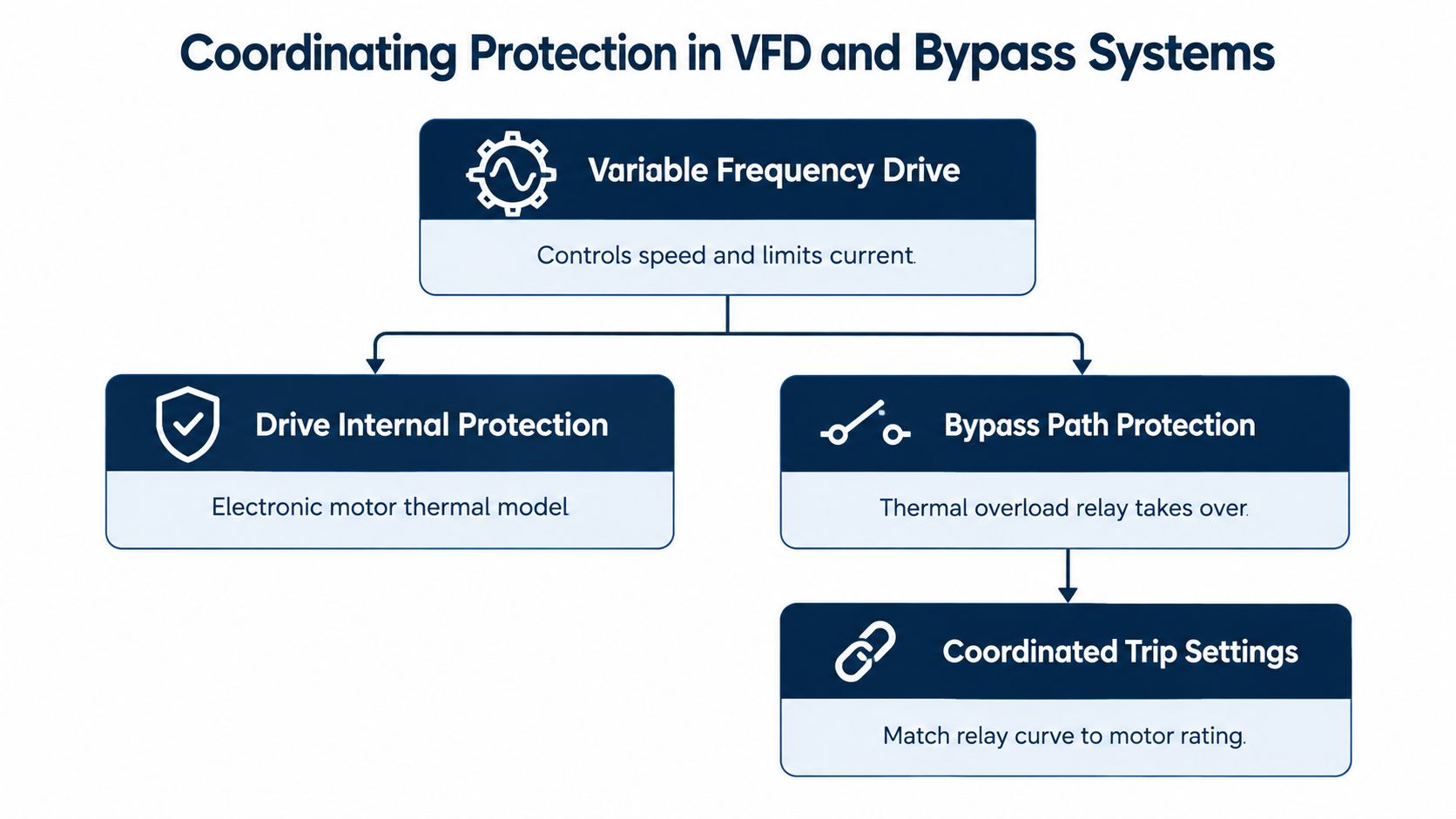
A drive can provide internal current limiting and thermal protection, but that does not make external overload protection optional. An overload relay protects against prolonged overcurrent, yet it is not a short-circuit device, so upstream clearing still has to be in place. Where a bypass contactor exists, the bypass path needs its own protection logic as well. Rockwell Automation's application note also points out that in multi-motor applications, individual overload protection belongs on the load side of the VFD so one motor's heating does not disappear inside aggregate drive current.
Where the protection belongs
A common mistake is treating the drive's current limit as a substitute for external protection. It is not. If the machine can run in bypass, that path needs its own protection arrangement. If several motors share one drive, each motor still has to be visible as an individual thermal risk.
Field rule: if the current measurement point cannot identify one motor's overload separately, the protection scheme is incomplete.
The fault boundary matters. An overload relay handles prolonged heating. Short circuits require upstream clearing. A nuisance trip during bypass start often points to the wrong trip class, a start profile that runs too long, or a mechanical load that is binding harder than expected. A trip during steady VFD operation usually points toward overload, poor cooling, wrong motor data, or drive tuning issues. For teams working through repeated faults, a structured troubleshooting path helps more than repeated reset attempts, and DUCHENG Industrial publishes a relevant guide on VFD overload fault diagnosis.
A Field Diagnostic Sequence for Relay Trips
A relay trip is not a cue to reset and hope. The first move is a short, disciplined check of the motor, the load, and the environment, especially in VFD and bypass systems where the same motor can behave differently on each path.
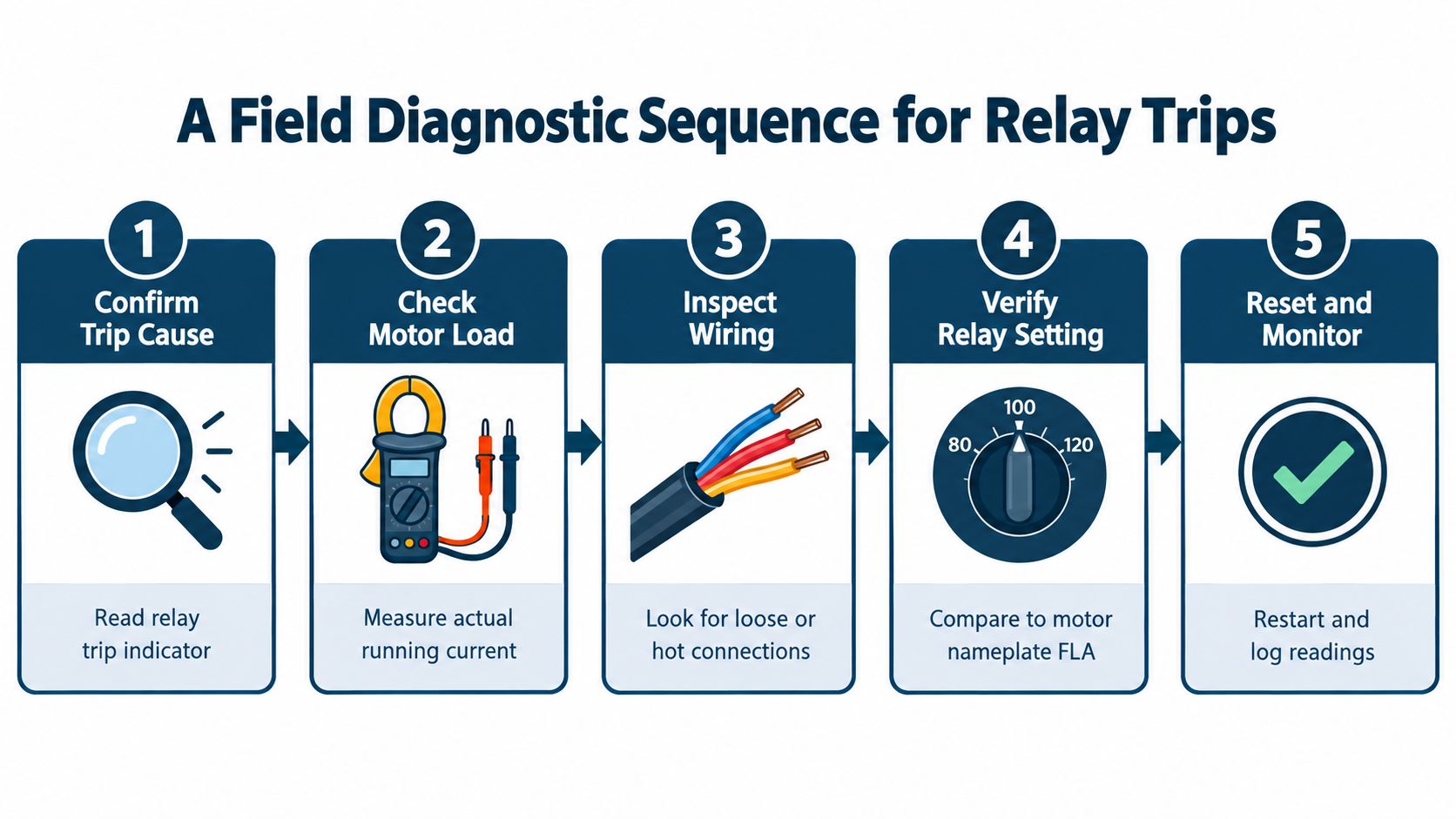
Work through the fault in order
- Confirm the trip cause. Read the relay indicator and identify whether the relay opened on overload or another protection event.
- Check motor load. Measure current on all phases and compare the running load with what the motor should be carrying.
- Inspect wiring and connections. Loose or hot terminations raise resistance and distort what the relay sees.
- Verify the relay setting. Compare the dial to the motor nameplate full-load current, not a guessed value.
- Reset and monitor. Restart only after the cause is understood, then log the readings while the motor is under normal load.
That sequence keeps the team from confusing electrical symptoms with mechanical ones. A phase imbalance, restricted airflow, bearing drag, or a process jam can all raise thermal stress without looking dramatic at the panel. If the motor is already hot, another start can eat into the remaining thermal margin fast, which is why repeated resets without diagnosis are a bad trade.
Ambient conditions matter too. Most bimetal relays are compensated around a fixed ambient reference, typically 20 °C per IEC 60947-4-1, so a hot enclosure can reduce margin faster than technicians expect. Cold versus hot starts can also change trip timing significantly, so capture the motor's thermal state before restarting. For teams working through repeated bypass faults, a structured path such as the VFD overload fault diagnosis guide helps separate a true overload from incorrect trip class selection or hidden mechanical binding.
Recognizing Blind Spots and Planning Electronic Upgrades
A thermal overload relay is simple, inexpensive to maintain, and easy to trust on steady loads. It also has clear limits. It will not show phase loss, ground faults, or load trends, so it cannot tell you whether a trip came from a genuine overload, a poor trip class choice, or a motor that is binding mechanically until the thermal threshold is reached.
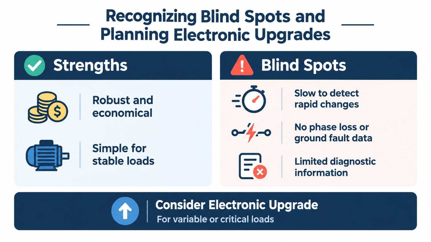
| Strengths | Blind Spots |
|---|---|
| Durable and economical | Slow to detect rapid changes |
| Simple for stable loads | No phase loss or ground fault data |
| Good fit for direct-on-line motors | Limited diagnostic information |
Where the application is critical, variable, remote, or already tied into plant monitoring, electronic monitoring makes more sense. Connected motor systems report current, temperature, load, and energy data, which gives maintenance teams a live picture instead of a single trip flag. That shifts the response from “reset and see” to “trend and act before the next stop,” but the added capability only pays off when downtime carries real cost. The thermal trip element still does one job, it does not explain why the motor tripped.
A practical upgrade screen
- Stable loads, low consequence: keep the relay if the machine is simple and downtime is tolerable.
- Frequent starts or high inertia: add better diagnostics if nuisance trips keep appearing.
- Remote or harsh sites: electronic monitoring is worth considering when inspection is difficult.
- Critical assets: upgrade when a blind trip costs more than the added complexity.
The point is to match protection depth to failure consequence. A relay that only says “tripped” can be enough on a stable feeder. On a drive that keeps stopping a production line, that is thin information.
Best Practices for Setting and Calibration in Harsh Environments
The safest setting rule is still the simplest one. Set the relay to the motor nameplate full-load current, then verify the result against actual running current, ambient temperature, and the manufacturer's instructions. If the number on the dial doesn't match the motor data, the relay isn't protecting the machine you think it is.
Tune for the environment, not the label
Hot rooms, dirty panels, and salty air all eat away at thermal margin. Conventional relays are usually built around a standard operating range, so a cabinet that runs hot can shift behavior enough to matter. That's why calibration isn't just about current, it's about thermal context.
Maintenance rule: a relay set correctly on paper can still trip early in a hot enclosure if the cabinet cooling is poor.
Routine checks should stay focused and practical. Confirm the mechanical trip action still works cleanly. Check for loose conductors and discoloration at the terminals. Make sure the relay hasn't been reset so often that the root problem gets buried under repeated start attempts.
DUCHENG Industrial's motor starter troubleshooting guide is relevant here because it aligns overload setting checks with the motor nameplate and trip verification workflow. That's the right mindset for plant teams that need to keep a starter dependable without turning every fault into a manual override.
What works in the field
- Set from the nameplate first. Don't use a guess based on frame size alone.
- Validate actual current under load. The running current should support the setting you chose.
- Respect thermal memory. A motor that's already warm won't behave like a cold one.
- Check the enclosure. Heat and contamination can shift relay response enough to create nuisance trips.
- Investigate repeated trips. Recurring events usually point to a mechanical or installation issue, not a relay that needs to be pushed higher.
That's how teams keep a protective device from becoming a recurring fault source. A disciplined setup saves more time than a loose one, because it prevents the same alarm from coming back every shift.
Treating the Trip as a Diagnostic Signal
A good maintenance supervisor doesn't ask how to stop the relay from tripping first. The better question is why the motor is building heat in the first place. A thermal overload relay is the messenger, not the problem, and the plant gets better results when technicians treat it that way.
One motor might need a different trip class because its load takes longer to accelerate. Another might be tripping in bypass because the relay is being asked to cover a start profile it wasn't selected for. A third may be healthy electrically but struggling because a bearing, conveyor, or pump is adding resistance that nobody checked. Those are different faults, and they need different fixes.
The best restart is a controlled one. Confirm the cause, verify the setting, check the mechanical load, then bring the motor back only when the evidence makes sense. That approach protects the winding, the process, and the people standing near the panel.
DUCHENG Industrial supports VFD and motor control teams with on-site troubleshooting, controlled restart procedures, maintenance, and repair services for drive assets. If your relays keep tripping in bypass, on startup, or under harsh enclosure conditions, visit DUCHENG Industrial to review lifecycle services that can help you isolate the cause and restore stable operation.