
Learn what causes a VFD overload fault, how to troubleshoot it, and the best prevention tips to keep your drive running reliably in 2026.
A VFD overload fault is a thermal-protection event: sustained motor current exceeds the allowable thermal limit, rather than producing only an instant current spike. Many drives can tolerate a short overload such as 150% load for 60 seconds, but a recurring trip usually points to a real process condition or a configuration error.
The production line is stopped, the operator has reset the drive twice, and the same alarm returns as soon as the conveyor reaches operating speed. The motor and drive nameplates appear correctly matched, so the first instinct is often to blame the VFD. That reaction wastes time. The drive is usually reporting that the motor has been working harder, heating faster, or operating under a thermal model that doesn't match the application.
A reliable diagnosis separates three possibilities: mechanical resistance, incorrect motor or protection parameters, and transient demand caused by an aggressive ramp. The following workflow helps maintenance teams prove which condition exists before replacing a drive or weakening its protection settings.
Table of Contents
- Understanding VFD Overload Faults
- Common Root Causes of Overload Trips
- Step-by-Step Troubleshooting Workflow
- Preventative Measures and Maintenance
- Overload Fault vs. Overcurrent Fault
- When to Escalate to Professional Services
Understanding VFD Overload Faults
The conveyor reaches production speed, runs through the first cycle, then stops with an overload code. The motor and drive nameplates match, yet the alarm returns after every reset. That pattern does not prove a failed VFD. It usually means the drive has accumulated enough estimated motor heating to intervene.
A VFD overload fault measures current over time, rather than reacting only to one brief disturbance. Its I2t thermal model estimates how quickly heat builds in the motor, then limits output or trips when continued operation could damage the windings or the drive's power section. This behavior is explained in field guidance on VFD overcurrent and motor overload causes.

The trip may occur several minutes after the load changes. Current at the exact fault instant can look ordinary because the thermal model has already integrated the earlier demand. A nameplate provides the rated operating point, not the motor's thermal limit under every combination of speed, duty cycle, ambient temperature, cooling airflow, load inertia, and restart frequency. Low-speed operation can be especially demanding when the shaft-mounted fan provides less cooling.
Why short overload capability matters
Drives commonly tolerate a short demand of 150% load for 60 seconds. That margin supports starting and transient torque without an immediate trip. It does not make continuous operation above the motor's thermal capacity safe. The protection must separate temporary demand from heating that continues through the cycle.
Use a three-part diagnostic loop:
- Prove mechanical resistance. Compare unloaded and loaded current, inspect bearings and couplings, and check for a blocked pump, restricted conveyor, or material buildup. A current increase that follows the process load points toward real mechanical demand.
- Verify the thermal model. Check motor voltage, rated current, frequency, speed, service factor, and overload settings against the motor data and actual duty. Incorrect values can make the drive estimate heating inaccurately, even when the nameplate horsepower appears correct.
- Test transient demand. Record the trip speed and acceleration time. If the fault occurs only during acceleration, an aggressive ramp may demand torque faster than the inertia or process can accept. A controlled ramp change can confirm the cause without weakening overload protection.
Record whether the trip follows startup, a particular speed, a product change, a hot shift, or repeated restarts. Each detail narrows the test.
Practical rule: Treat the overload code as a report about motor heating, not as proof that the VFD electronics have failed.
Resetting the alarm, raising the overload limit, or replacing the drive can hide the actual defect. Compare current, time, speed, temperature, and process state, then change one likely cause at a time. A sustained trip is diagnostic evidence, not merely an interruption.
Common Root Causes of Overload Trips
A motor may run normally for hours, then trip when the line is loaded, the plant supply changes, or a new batch starts. The code usually belongs to one of three groups: electrical conditions, mechanical demand, or configuration mismatch. These causes can overlap. A weak supply can raise current, while a short acceleration ramp can reveal a restriction that steady operation does not expose.
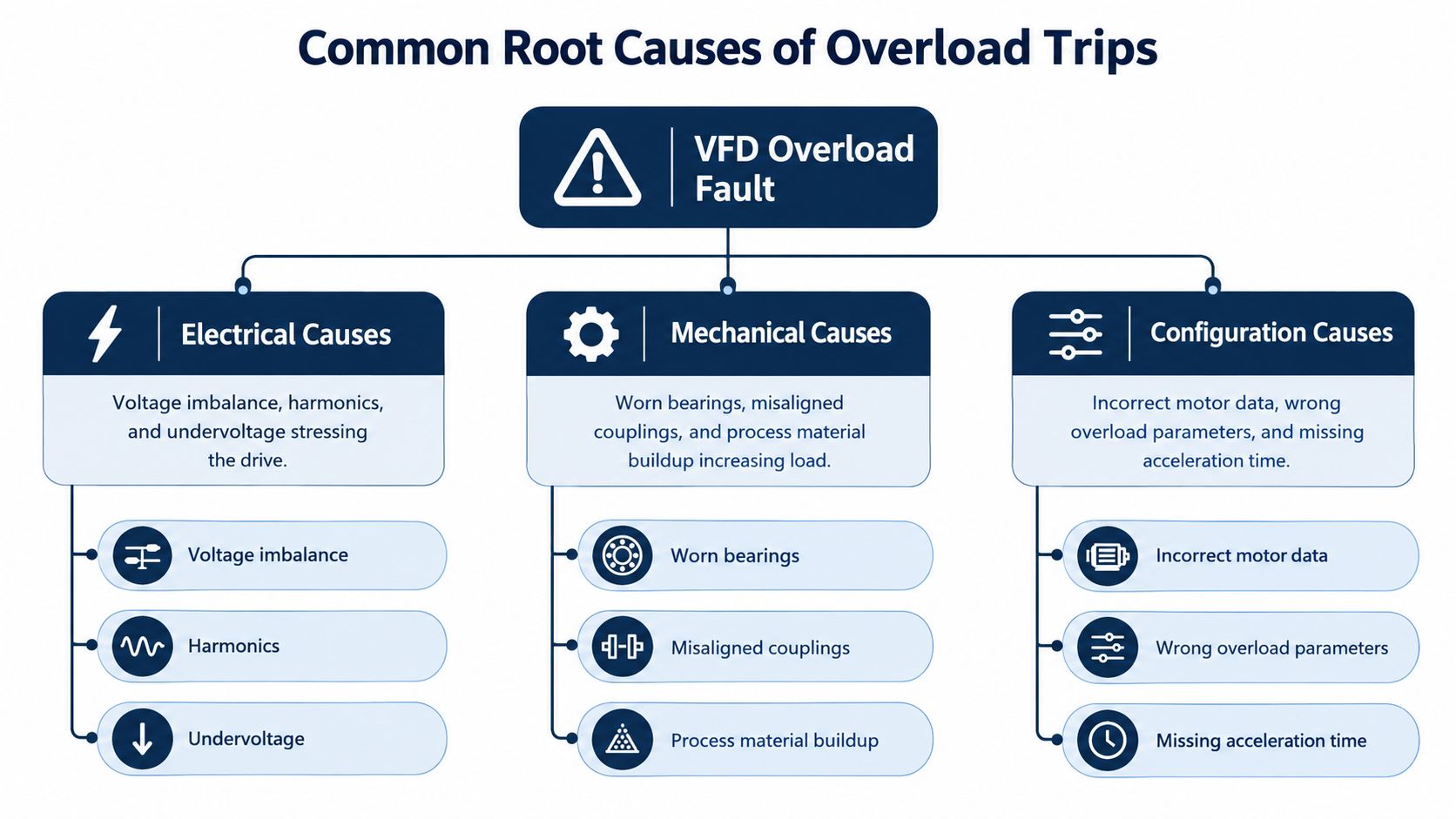
Electrical conditions
Voltage imbalance needs a loaded measurement. One phase may carry excessive current even when the average motor current appears acceptable. As a practical diagnostic threshold, keep current unbalance below 10% when operating below full-load amps and below 5% at or above full-load amps, consistent with manufacturer commissioning guidance on warnings, trips, faults, and failures. Treat those values as screening thresholds, not permission to overlook the motor or process.
Measure phase-to-phase voltage while the motor is operating, not only with it stopped. Loose terminations, a weak supply, upstream imbalance, and voltage changes caused by other plant equipment can all increase the current needed to produce torque. Undervoltage creates a similar symptom because the motor may draw more current to maintain the requested load.
Mechanical demand
The drive measures the torque needed at the shaft. It cannot identify whether that torque comes from a blocked pump, worn bearing, misaligned coupling, tight belt, damaged gearbox, or material buildup in the process path.
A current rise over days or weeks points toward bearing wear, coupling misalignment, gearbox drag, or process plugging rather than a sudden drive defect. A conveyor may run freely with no product while its rollers add resistance under load. A pump may operate normally with no flow, then overload when a restricted line shifts its operating point.
Pumps and fans require particular attention because power demand rises with the cube of rotational speed. A modest increase in speed can produce a substantial rise in load power. A changed speed reference can therefore turn a healthy application into an overload condition.
Use the trip pattern to separate causes. Current that increases with process load supports genuine mechanical resistance. A trip at a repeatable speed or during acceleration points toward transient demand. A trip after extended running, despite correct mechanical movement, raises suspicion of thermal model mismatch or insufficient cooling.
Configuration mismatch
A VFD bases its motor protection behavior on entered data and selected settings. Incorrect motor voltage, frequency, rated current, speed, power, or control data can make the thermal model inaccurate. The nameplate may be correct while the drive's internal motor representation is wrong. Real-world thermal limits also depend on cooling, duty cycle, ambient conditions, and installation, not nameplate horsepower alone.
Acceleration time is another frequent trigger. A high-inertia conveyor, mixer, fan, or roller may need a longer ramp to reach speed without sustaining excessive current. Changing the ramp can confirm a transient problem, but it cannot correct a binding shaft or an overloaded process.
Protection class must match the duty. Frequent starts, cyclic loading, and high-inertia applications create a different thermal pattern from a steady fan load. Raising the overload limit or choosing a less protective setting to stop nuisance trips can conceal the fault unless the motor, duty cycle, cooling, and manufacturer limits have been checked.
Step-by-Step Troubleshooting Workflow
Start with the event, not the replacement part. A structured diagnostic loop should answer three questions in sequence: Is the load physically difficult to turn? Is the drive calculating motor heating correctly? Is the overload created only by the operating profile?
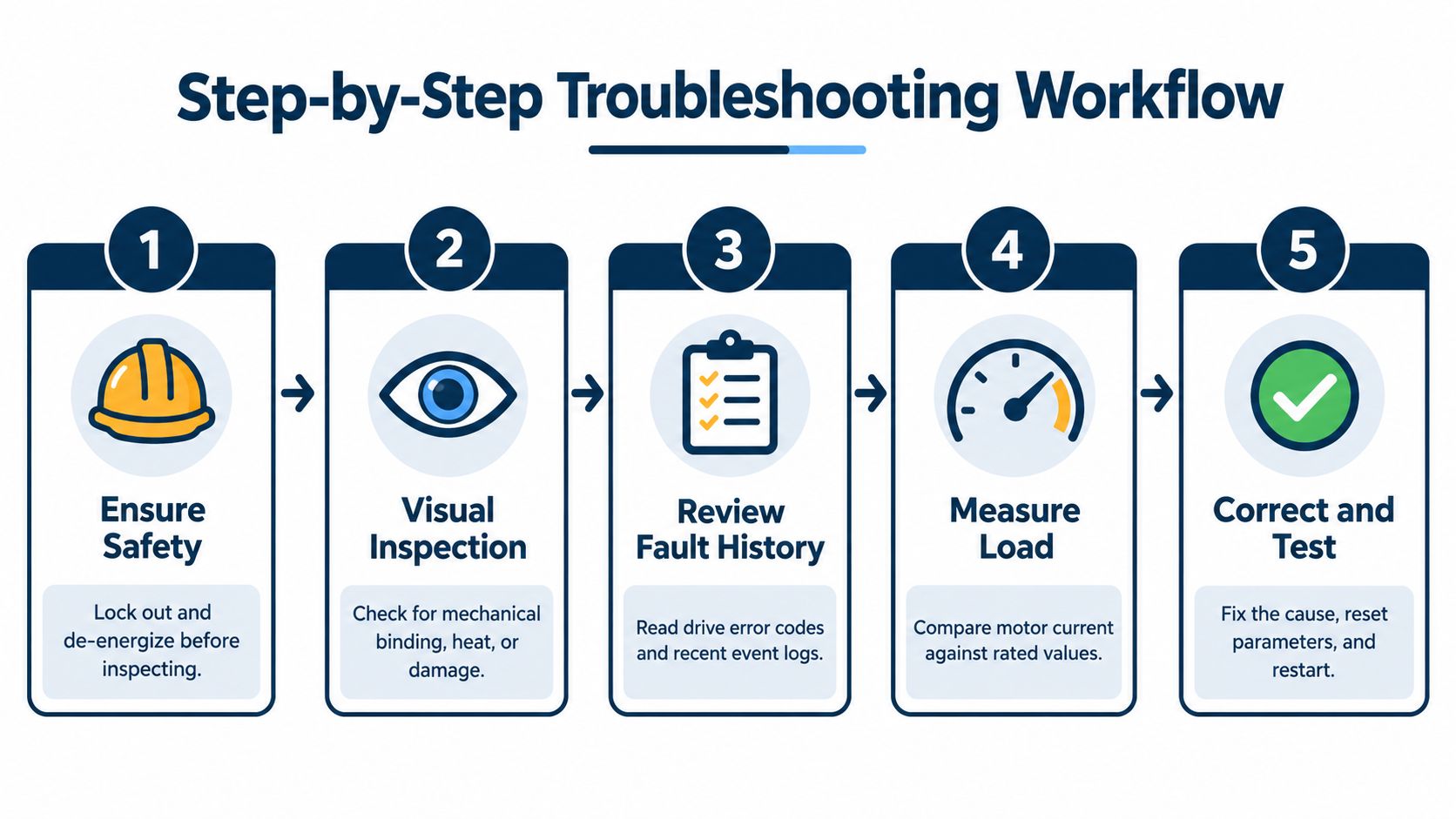
1. Make the area safe
Follow the site's isolation procedure before opening the enclosure, touching motor terminals, or inspecting rotating equipment. A VFD can retain hazardous energy after the incoming supply is removed, so wait for the manufacturer's discharge indication and verify the absence of voltage using approved equipment.
Ask the operator for the operating context before resetting anything:
- Fault timing: Did the trip occur at startup, during acceleration, at a particular speed, or after extended operation?
- Process condition: Was the line full, blocked, unusually heavy, or recently changed?
- Recent work: Were motor leads, parameters, couplings, bearings, or control logic changed?
- Environment: Was the panel hot, dusty, contaminated, or short of airflow?
The answers establish a baseline for the next checks.
2. Inspect the mechanical path
With the equipment safely isolated, check whether the driven machine turns as expected. Inspect bearings, couplings, belts, gearboxes, seals, pump paths, fan blades, and conveyor components. Look for heat, unusual noise, material buildup, rubbing, and signs of misalignment.
Don't rely on a no-load spin test alone. Some defects create resistance only when the equipment reaches operating temperature or process pressure. If the overload occurs only when material enters the machine, inspect the process side rather than focusing exclusively on the motor.
3. Review the drive record
Read the fault history and note current, output frequency, speed reference, DC bus behavior, and the time between start and trip when those values are available. A trip at one repeatable speed is more useful than a vague report that the drive “sometimes stops.”
The DUCHENG Industrial VFD troubleshooting guide can be used alongside the manufacturer's documentation when checking fault history, load conditions, motor circuits, and acceleration settings.
4. Measure under load
Use a suitable clamp meter or power-quality instrument to measure each motor phase while the machine accelerates and while it operates at the point where the fault occurs. Compare the readings with the motor's rated current and observe whether one phase departs from the others.
Then measure the incoming voltage under the same plant conditions. A balanced reading with the motor stopped doesn't prove that the supply remains healthy when the process and neighboring equipment are active.
5. Verify parameters, then test one change
Compare every entered motor value against the physical nameplate. Check rated current, voltage, frequency, speed, control mode, overload class, minimum and maximum frequency, and acceleration time. Confirm that the motor connected to the drive is the motor represented by those settings.
If the mechanical path is free and the parameters are correct, test a longer acceleration ramp under controlled conditions. Monitor current during the ramp and record whether the trip disappears, moves later in the cycle, or remains unchanged. A ramp adjustment that changes the symptom supports a transient-demand diagnosis, but it doesn't justify leaving the machine at an unsafe operating point without reviewing the duty.
Use the same discipline when changing protection settings. Change one parameter, test, and document the result. Repeated resets and multiple undocumented changes destroy the evidence needed to isolate the fault.
<iframe width="100%" style="aspect-ratio: 16 / 9;" src="https://www.youtube.com/embed/xcsiqtezsIs" frameborder="0" allow="autoplay; encrypted-media" allowfullscreen></iframe>Preventative Measures and Maintenance
Overload prevention begins before the first trip. Correct commissioning gives the drive an accurate motor model and gives the maintenance team a documented reference for current, speed, ramp behavior, and normal operating temperature. Without that baseline, a gradual rise in current can look like a random event.
Commission for the real duty
Enter the motor's actual nameplate data rather than relying on factory defaults. Confirm the control mode, motor identification procedure, overload class, acceleration and deceleration behavior, minimum speed, and intended load profile. Test the machine through its normal operating range, including the conditions that create the highest torque demand.
The correct setting depends on how the machine operates, not on the motor's nominal rating. An intermittent conveyor, a mixer with changing material density, and a continuously running fan place different thermal demands on the motor and drive.
Watch for slow deterioration
Maintenance teams should trend current alongside production conditions. A small upward movement over time may be more valuable than a single alarm because it can identify increasing friction before the drive reaches its protection limit.
During planned shutdowns, inspect:
- Cooling paths: Remove contamination from heatsinks, filters, fans, and enclosure ventilation routes.
- Mechanical alignment: Check couplings, belts, shafts, bearings, and gearbox condition.
- Electrical terminations: Inspect for looseness, discoloration, heat damage, and phase irregularities.
- Process restrictions: Check pump strainers, ducts, conveyors, screens, and chutes for buildup or plugging.
- Drive records: Preserve fault history and compare new events with the commissioning baseline.
Infrared inspection can help identify abnormal heating at terminals, motor connections, and drive components, but it should support electrical measurements and mechanical inspection rather than replace them. A cool enclosure doesn't prove that a bearing is healthy, and a warm terminal doesn't prove that the motor itself is overloaded.
Control the environment
Heat, restricted airflow, dust, and contamination reduce thermal margin. Keep the enclosure condition consistent with the drive's installation requirements and inspect cooling hardware during scheduled outages. Harsh environments require a maintenance interval based on contamination and operating conditions, not a calendar assumption copied from a clean electrical room.
Maintenance principle: Prevent the current trend from becoming a fault. Rising current, changing ramp behavior, and increasing cabinet temperature are early warnings that deserve a work order.
A reset policy also matters. Operators should know when a single reset is permitted and when repeated trips require maintenance intervention. A protection device is doing its job when it stops a motor before accumulated heat becomes damage. The maintenance program should preserve that protection while removing the condition that keeps triggering it.
Overload Fault vs. Overcurrent Fault
Both faults involve excessive current, but they demand different first checks. An overload fault is generally a time-integrated thermal event. An overcurrent fault is typically an immediate response to a severe electrical or mechanical condition, such as a short circuit or stalled rotor.
| Feature | Overload Fault | Overcurrent Fault |
|---|---|---|
| Trip timing | Develops after current and heat accumulate | Can occur almost instantly |
| Typical causes | Excessive mechanical load, poor cooling, incorrect parameters, voltage imbalance, or an aggressive duty profile | Short circuit, ground fault, damaged motor cable, stalled rotor, or severe instantaneous demand |
| Common operating pattern | Motor may run normally before tripping | Drive may trip during starting or immediately after a command |
| First diagnostic focus | Load torque, current trend, thermal settings, motor data, and cooling | Motor leads, insulation, wiring, terminals, rotor condition, and fault history |
| Reset approach | Find why the motor is heating before restarting | Isolate and test the power path before applying another start command |
A drive that trips after a predictable period under load should not be diagnosed as though a phase-to-phase short has occurred. Conversely, a drive that trips immediately with an abnormal current indication should not be “fixed” by increasing acceleration time.
The distinction is especially important when fault codes use similar abbreviations across different drive families. Read the manufacturer's definition, capture the event data, and confirm whether the code represents a thermal overload, output overcurrent, ground fault, or another protection function. The DUCHENG Industrial guide to VFD fault codes provides a reference point for organizing that review.
Never bypass protection to keep production running. If the fault type is uncertain, isolate the motor circuit and test the cable, motor, and driven machine separately according to the site's electrical safety procedure. A wrong diagnosis can turn a protective trip into a damaged motor, failed power section, or unsafe restart.
When to Escalate to Professional Services
Internal troubleshooting is appropriate when the fault has a clear trigger and the plant team can safely measure the relevant conditions. Escalation becomes necessary when the drive keeps tripping after the load, supply, parameters, and cooling have been checked, or when the event pattern changes without an identifiable process cause.
Be cautious when the drive shows multiple unrelated faults, loses parameter data, reports inconsistent current, smells overheated, or trips with the motor disconnected according to the manufacturer's test procedure. These symptoms can point to sensing problems, aging power components, control-board issues, or damage that a basic commissioning check won't prove.
Choose the service level for the failure
A recurring production fault often needs a controlled recovery plan rather than another reset. DUCHENG Industrial's Rapid Restore service provides structured on-site diagnosis and controlled restart procedures for unplanned drive faults. That approach keeps the team focused on fault isolation, safe recovery, and evidence collection while limiting the risk of restarting into the same damaging condition.
A drive that has suffered internal damage may require Deep Repair, including disassembly, bench diagnostics, component-level repair, and functional testing in a controlled workshop environment. Workshop repair is more appropriate when technicians need to inspect power modules, sensing circuits, capacitors, control boards, or other assemblies that can't be verified reliably in the cabinet.
For medium- and high-voltage drives, shipping may introduce unnecessary handling risk and extend the outage. On-site Blue Reconditioning provides a route for reconditioning those drive systems at the facility when transport is impractical. The right choice depends on voltage level, physical size, site access, spare availability, failure evidence, and the need to return the asset to service within a planned shutdown.
Escalate with a useful evidence pack
Professional technicians work faster when the plant preserves the conditions surrounding the fault. Provide the drive model and firmware information, motor nameplate details, parameter backup, fault history, phase-current readings, incoming-voltage readings, trip timing, process state, recent maintenance records, and photographs of the enclosure and mechanical equipment.
A professional diagnosis should explain why the fault occurred, what was corrected, and how the restart was verified. Replacing a drive without answering those questions leaves the original overload condition in service.
The objective isn't only to clear today's alarm. It is to separate a real process overload from a bad thermal model, transient ramp demand, power-quality problem, or internal drive failure, then document the result so the next shift can recognize the same pattern quickly.
DUCHENG Industrial supports VFD commissioning, fault diagnosis, Rapid Restore response, Deep Repair, preventive maintenance, and on-site reconditioning for industrial drive systems. If your team is dealing with a recurring VFD overload fault, visit DUCHENG Industrial to request service and discuss the evidence needed for a controlled diagnosis.