
Learn how to choose a harmonic filter for VFD systems using IEEE 519, PCC measurements, filter types, and checks that protect drives and transformers.
The drive trips again during a production changeover. Its cabinet looks serviceable, but the transformer runs hotter than the process load seems to justify, and the standby generator struggles with loads that run on utility power. Before ordering a harmonic filter for VFD equipment, you need to establish whether you're dealing with a drive fault, a distorted supply, or an interaction between the two.
Table of Contents
- Why Harmonics From a VFD Can Cause Heat and Trips
- How VFD Harmonics Reach the Point of Common Coupling
- Comparing Passive Active and Hybrid Harmonic Filters
- Sizing a Harmonic Filter Against IEEE 519
- Installing and Commissioning the Filter Safely
- What Filtering Changes for Drives Transformers and Power Quality
- Choosing the Next Step for Your Drive System
Why Harmonics From a VFD Can Cause Heat and Trips
A pump drive trips when a second production line starts. The drive passes its own checks, yet the shared transformer begins running hotter as more equipment comes online. The timing points to a system interaction worth investigating.
A conventional rectifier front end draws current in pulses rather than as a smooth sine wave. Those pulses contain harmonic components. When several drives operate together, their combined effect depends on the supply impedance and the plant's operating state, not just on each drive's nameplate rating.
Why healthy drives can create a shared problem
The transformer and cables carry the combined load, much like a plant's main water line supplies several branches at once. A drive can operate normally while its current pulses add to distortion elsewhere in the system. A filter can reduce harmonic distortion, but it will not correct a failed component, poor cooling, or an unrelated protection problem.
Treat symptoms as a starting point
Before considering filtering, compare the fault history with operating conditions:
- A local cabinet problem: Check cooling, contamination, connections, and the recorded fault.
- An operating-state problem: Record whether trips coincide with particular drive combinations, capacitor switching, or generator operation.
- A shared-supply concern: Compare conditions at the affected feeder with measurements at the facility's point of common coupling.
Heat and trips call for investigation; they do not, on their own, justify buying a filter. Keep the fault history alongside power-quality measurements. A reading at the drive terminals may miss conditions elsewhere, and a distorted waveform alone does not establish the cause of every trip.
The filter decision depends on what the measurements show at the point of common coupling, how strong the supply is, which loads share it, and how the plant operates across utility and generator modes. Measure those conditions before selecting equipment.
How VFD Harmonics Reach the Point of Common Coupling
The point of common coupling, or PCC, is the interface between the utility source and customer loads. Think of it as a shared electrical property line. It's the boundary used to judge the facility's effect on the connected supply, not automatically the terminals of the drive you're repairing.
The distinction becomes clear when you trace the electrical path.
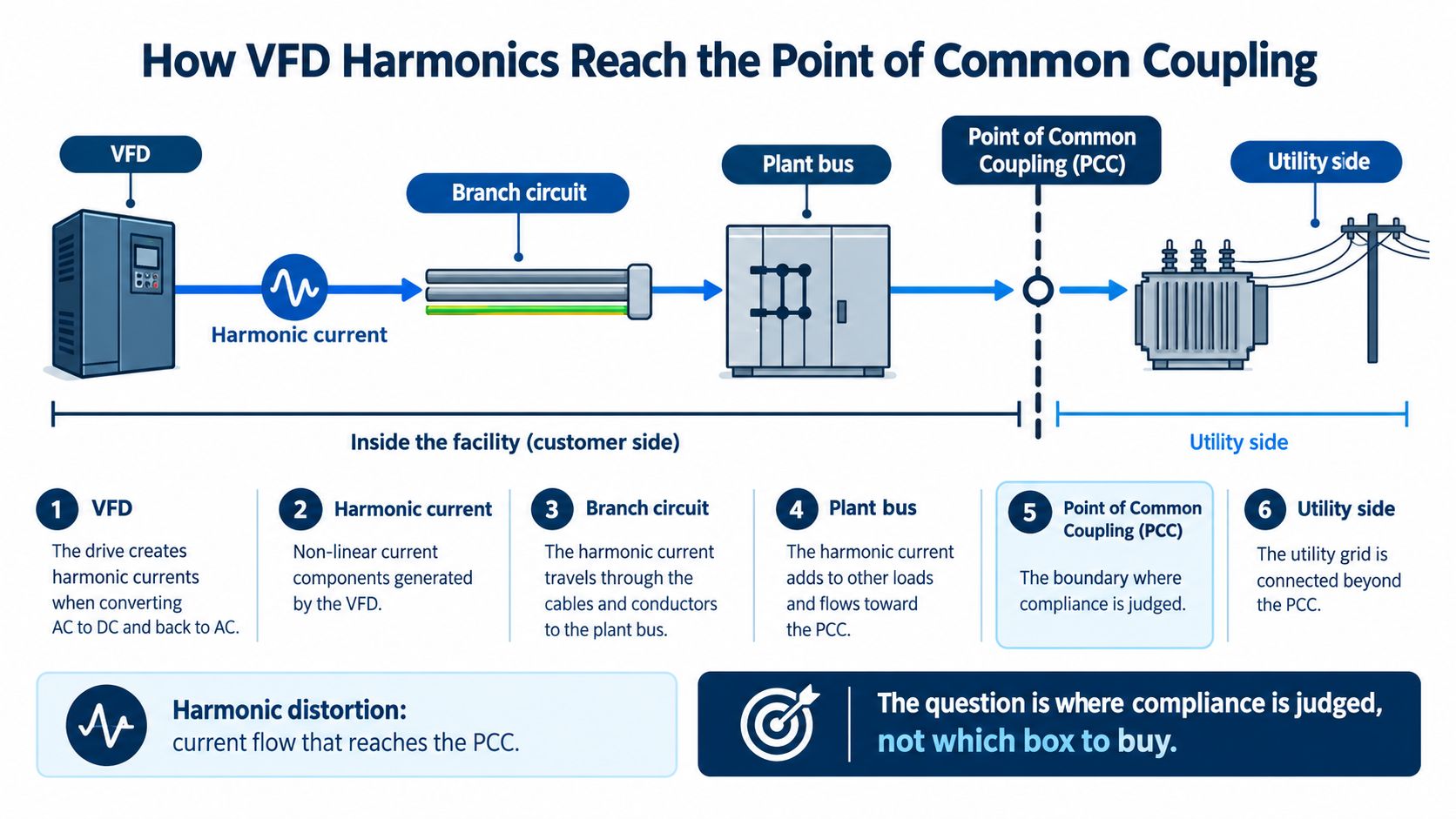
Follow the shared path
Harmonic current passes through branch circuits and shared plant infrastructure. The voltage distortion associated with that current depends on the impedance it encounters. Transformer impedance, available short-circuit strength, parallel nonlinear loads, and demand conditions therefore affect what appears at the PCC.
The same drive can produce a different system-level result after a transformer change or a switch to generator supply. That doesn't necessarily mean the drive changed. Its electrical surroundings changed.
For the conversion process inside the equipment, this explanation of how a variable frequency drive works provides useful background. Keep that device-level explanation separate from the question of where compliance is assessed.
Understand what the reference limits mean
The 1992 revision of IEEE 519 established a foundational industrial reference for harmonic control, with commonly cited general-system voltage guidance of 5% total distortion and 3% for an individual harmonic, assessed at the PCC rather than imposed universally on each drive (historical explanation of IEEE 519 and harmonic limits).
Current distortion requires another distinction. Total demand distortion, or TDD, relates harmonic current to maximum demand current. It isn't interchangeable with a drive-terminal current THD reading taken at whatever load happens to be running.
For the maintenance manager, the survey request should identify:
- PCC voltage quality: Total voltage distortion and individual harmonic orders.
- Demand conditions: Demand current and the plant's operating-load variability.
- Source characteristics: Transformer impedance and utility or generator short-circuit strength.
- Connected load mix: Which nonlinear loads share the supply and when they operate.
Don't let a vendor substitute a favorable reading at one drive for that survey. The measurement location and operating state are part of the result.
Comparing Passive Active and Hybrid Harmonic Filters
A pump line runs steadily during one shift, then cycles on and off during another. The same drive can create a different harmonic burden as its load changes, while other equipment on the supply adds its own distortion. Filter choice therefore starts at the point of common coupling (PCC): short-circuit strength, the mix of connected loads, and the plant's operating states matter more than a match to one drive nameplate.
Match the mechanism to the load
Passive filters use inductors and capacitors to impede or redirect selected harmonic currents. A tuned branch targets particular harmonic orders, while a broadband design acts across a wider range. Both depend on the supply and operating conditions, so neither is a universal fix.
Published guidance describes passive-filter current distortion in the range of 5–10%, with performance potentially worsening at partial load or when voltage distortion is already present. Treat that as reported behavior, not a guarantee of PCC compliance. Check how the filter performs across the plant's actual operating states.
Active filters measure distortion and inject corrective current. Their response can suit changing load mixes, provided the sensing arrangement and available correction capacity fit the system. A hybrid pairs passive branches for the more predictable part of the harmonic burden with an active stage for the remainder. Verify that the passive stage is correctly engineered before relying on the active stage to compensate.
Harmonic Mitigation Options for VFD Systems
| Option | How it acts | Typical behavior | Main risk to check |
|---|---|---|---|
| Tuned passive | Routes selected harmonic orders through a low-impedance branch | Concentrated attenuation for a predictable spectrum | Resonance and background harmonics |
| Broadband AC passive | Combines series impedance with broader filtering branches | Attenuation across several components | Partial-load behavior and reactive current |
| Active | Measures distortion and injects opposing current | Adapts correction as loads change, within its capacity | Current capacity, sensing, and control complexity |
| Hybrid | Splits correction between passive and active stages | Addresses predictable and changing components | Interaction between stages |
| Multipulse conversion | Uses phase-shifted rectifier supplies | Reduces characteristic harmonics through cancellation | Transformer arrangement and remaining PCC distortion |
Twelve-pulse conversion is a drive architecture, not a standard add-on filter. Paired six-pulse bridges receive supplies separated by 30 electrical degrees. Published guidance reports harmonic reduction of up to approximately 85% compared with six-pulse arrangements, but that figure does not establish compliance at the PCC.
For a retrofit, assess the whole shared supply rather than selecting equipment from one drive's nameplate. A multi-brand lifecycle service team can also review cabinet condition, commissioning needs, and maintenance access alongside the harmonic study. That helps keep the filter decision tied to plant conditions, not just the drive model.
Sizing a Harmonic Filter Against IEEE 519
A filter sized to one drive's horsepower can still miss the plant's actual problem. Picture a drive room where several units run together during production, then operate at partial load overnight. The right filter rating depends on what distortion reaches the point of common coupling (PCC) across those operating states, and on how strong the supply is there.
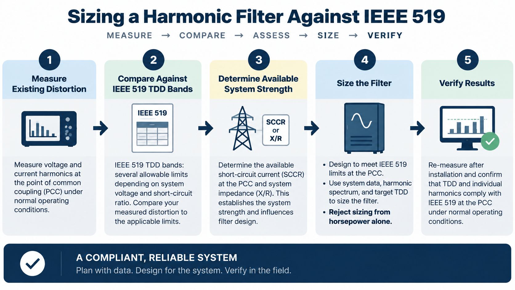
Establish the applicable current limit
The ratio (I_{SC}/I_L) compares the available short-circuit current at the PCC with the maximum demand current. A low ratio means the supply is weak relative to the load, so the applicable IEEE 519 current-distortion limit is tighter. Published guidance gives TDD limits of 5% below 20, 8% from 20 to 50, 12% from 50 to 100, 15% from 100 to 1,000, and 20% above 1,000. It also lists voltage-distortion limits of 3% for special systems, 5% for general systems, and 10% for dedicated drive systems (PCC distortion categories and system guidance).
The designer should confirm the applicable standard edition, voltage class, PCC boundary, and any stricter site requirements. These limits are not a substitute for checking the actual system conditions.
Set the design duty and acceptance criteria
Use the earlier site survey to establish the measured distortion, supply conditions, and connected loads. Then define the operating envelope the filter must handle: production peaks, reduced-load periods, generator operation, and transitions between supply sources. A filter that performs well during one steady operating point may behave differently when the load mix or source impedance changes.
Agree on acceptance requirements before selecting equipment. Specify the PCC measurement location, the operating states to be tested, the required distortion performance, and the records needed to demonstrate results. These details turn a general target into a testable design.
Capacitors and upstream impedance can form a resonant circuit, much like a spring that responds strongly at a particular frequency. Detuning means designing the combination so its resonant frequency does not coincide with a characteristic harmonic or an existing background component.
A filter's current rating shows how much correction current it can carry. The system study determines whether that correction addresses the plant's PCC performance.
Compare filtering with line reactors and low-harmonic drive configurations. Review current distortion, displacement power factor, losses, space requirements, resonance exposure, and maintenance needs for the full load mix and operating envelope.
The design deliverable should document its assumptions, predicted performance, and acceptance method, not just identify a filter model and ampere rating.
Installing and Commissioning the Filter Safely
A correct study can still be undermined by an installation that differs from the approved design. Treat the work as a modification to the electrical system, with qualified personnel, approved isolation procedures, and manufacturer instructions.
Use the installation checklist to keep physical checks separate from performance acceptance.
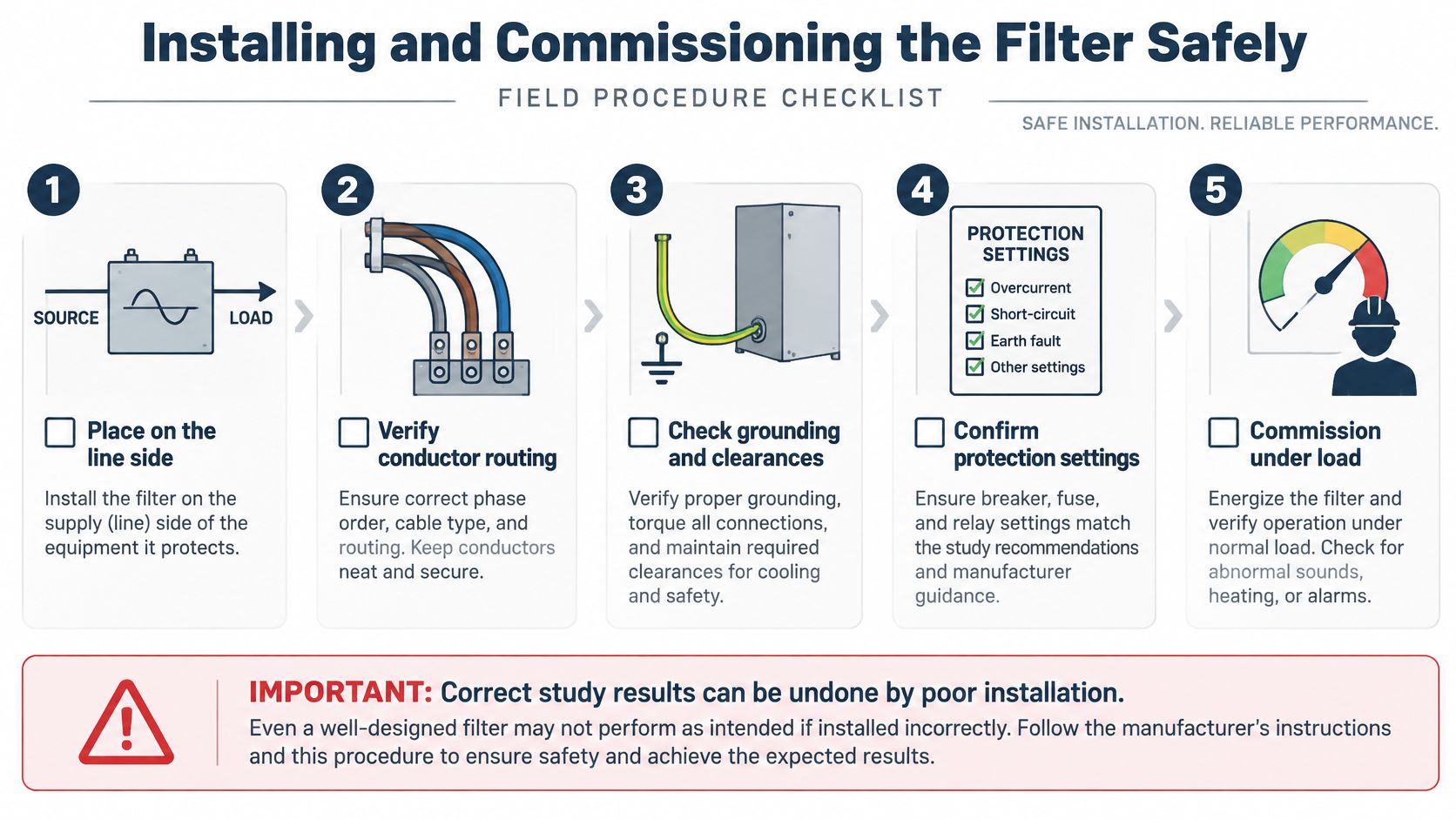
Verify the installation before energizing
Confirm that the line-side equipment is connected at the location specified by the design. A drive-feeder passive filter and a bus-connected active filter don't share an interchangeable wiring arrangement.
Check conductor routing, terminations, protective-earth continuity, clearances, and protection settings. Confirm that cooling arrangements account for the added equipment rather than assuming the existing cabinet has spare thermal capacity.
Identify existing power-factor correction capacitors and their switching states. They belong in the commissioning record because their interaction with the modified system must be assessed.
Test the operating envelope deliberately
A maintenance supervisor should require a controlled sequence:
- Capture the baseline: Record spectra and operating conditions before the filter is energized.
- Begin with light load: Observe voltage, current, alarms, and component behavior before increasing duty.
- Apply the planned VFD combinations: Include concentrated drive loading while other plant loads are reduced.
- Check alternate supply operation: Where applicable, conduct an approved generator or transfer test.
- Record acceptance evidence: Retain PCC results, equipment observations, settings, and any unresolved restrictions.
Minimum plant load combined with maximum VFD load deserves particular attention because lightly loaded conditions can worsen resonance and harmonic amplification. Acceptance should also address capacitor overvoltage, detuning, thermal loading, and interactions with generators or correction capacitors (IEEE harmonic-control reference).
Include the existing drive parameters and protections in the work scope. A new filter doesn't replace a sound restart procedure, and it shouldn't become an excuse to bypass unresolved faults. A VFD commissioning checklist can help organize those drive-specific checks.
Handover condition: Don't sign off on a feeder-only improvement when the acceptance requirement applies at the PCC.
Document any operating states that couldn't be tested. An untested generator condition should remain an explicit limitation, not disappear into a general statement that commissioning is complete.
What Filtering Changes for Drives Transformers and Power Quality
After a filter is commissioned, the useful question is whether equipment runs cooler or trips less often under comparable operating conditions. A smooth waveform alone cannot answer that. The filter's effect depends on its performance at the point of common coupling (PCC), where the plant's drives, other loads, and utility or generator supply meet.
A published generator-PCC case reported 4.8% current distortion and 3.07% voltage distortion, against a 5% site criterion. Those figures describe that installation and its stated criterion; they do not predict results at a plant with a different supply strength, load mix, or operating state.
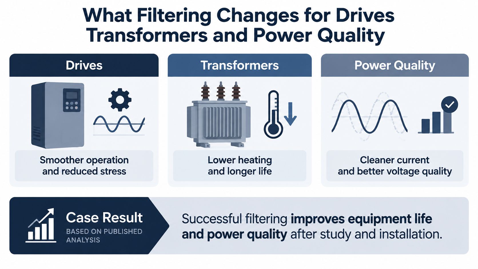
Connect electrical results to equipment condition
Lower harmonic current can reduce the additional heating it causes in transformers, cables, and generators. After commissioning, trend transformer temperature against load and ambient temperature. A cooler transformer at a lighter load does not by itself show that the filter caused the change.
Filter capacitors also draw reactive current, and a poorly selected passive filter can interact with system capacitance and create resonance. As noted earlier, filter choice depends on the electrical system, not just the drive nameplate.
Cleaner supply conditions may support steadier drive operation, but they do not correct cabinet contamination, poor cooling, incorrect protection settings, or internal drive faults. Equipment life also depends on these conditions, so lower electrical stress alone cannot support a specific life-extension claim.
Keep an operating record rather than a screenshot
One drive's current-distortion reading does not describe the rest of the plant. Production schedules change, and so can the harmonic mix at the PCC.
Compare records taken under similar conditions:
- PCC performance: Voltage and current distortion, with measurement definitions recorded.
- Targeted components: The individual harmonic orders the filter was designed to reduce.
- Thermal trends: Transformer or generator temperatures, alongside process load and ambient conditions.
- Operational behavior: Drive trip history under comparable production and supply conditions.
If temperatures fall, check that loading and ambient conditions are comparable before attributing the change to filtering. If trips continue, review fault records; the original diagnosis may not have covered every cause.
Evaluate financial impact separately. Reduced distortion alone does not establish payback. Use site-specific loss estimates, energy costs, maintenance records, and downtime history to assess the economics.
Choosing the Next Step for Your Drive System
The next useful purchase may be a survey rather than a filter. If you can't identify the PCC, the supply strength, and the operating state behind the complaint, you don't yet have a reliable basis for choosing hardware.
A drive nameplate remains useful for equipment compatibility. It doesn't establish how the shared electrical system will behave.
Put the work in the right order
- Confirm the boundary: Agree where performance will be assessed and who approves the acceptance criteria.
- Capture the evidence: Collect spectra and source data across the operating states that matter to production.
- Compare engineering options: Evaluate filters, reactors, and alternative drive architectures against distortion, resonance, losses, and maintenance constraints.
- Plan the handover: Require before-and-after measurements and a record of tested and untested conditions.
For a recurring trip problem, combine power-quality work with drive-condition assessment. Otherwise, you risk solving a supply issue while leaving a contaminated cabinet or unresolved protection problem untouched.
Choose support that fits the installed assets
An independent power-quality engineer, an electrical system designer, or a multi-brand lifecycle drive service provider may each contribute to the work. Ask who will perform the measurements, evaluate the system model, coordinate installation, and remain responsible for acceptance documentation.
For larger assets, also consider what happens if the inspection identifies a drive problem rather than a filter requirement. On-site diagnosis, workshop repair, preventive maintenance, and medium-voltage reconditioning address different constraints, particularly when transporting equipment is impractical.
Regional field coverage matters when the work must fit a shutdown or emergency response. For facilities in China or Thailand, confirm local availability, emergency contact arrangements, and the scope that can be completed on site.
Book the power-quality and drive-condition review before issuing the filter purchase order. That sequence gives procurement a defensible specification and gives maintenance a result it can verify.
DUCHENG Industrial provides multi-brand lifecycle services for low-, medium-, and high-voltage drives, including commissioning, preventive maintenance, troubleshooting, repair, and on-site reconditioning. Visit DUCHENG Industrial to request a power-quality and drive-condition review, bringing your single-line diagram, trip history, and planned shutdown window so the filter decision can be assessed alongside the existing drives.