
Learn how does a variable frequency drive work from rectifier to inverter, PWM control, and real plant impacts on harmonics, heat and diagnostics.
A lot of drive questions start the same way on the plant floor. The pump is moving too much product, the fan is pulling harder than the process needs, or the line runs fine at full speed but turns unstable when operators try to control flow with a valve, damper, or bypass. The motor itself is healthy. The problem is that the motor only knows one habit, line speed.
That's usually the moment someone asks, how does a variable frequency drive work, and they don't want the sales version. They want the version that helps them decide what to commission, what to measure, and what to suspect when the cabinet trips on a hot afternoon.
Table of Contents
- Introduction Why Motor Speed Control Matters on the Plant Floor
- Core Principle How Frequency Controls Motor Speed
- Inside the Drive The Three Power Conversion Stages
- Control Methods That Shape Output Behavior
- Waveforms Signals and Power Quality in Real Operation
- Heat Contamination and Aging Inside Industrial Cabinets
- Putting Knowledge to Work Commissioning Diagnostics and Repair Choices
Introduction Why Motor Speed Control Matters on the Plant Floor
On many sites, speed control starts as a process problem, not an electrical one. A cooling water pump may be oversized for normal demand. A combustion air fan may need steady adjustment across changing operating conditions. If the motor stays tied directly to line frequency, the usual workaround is to choke the system mechanically. The machine still spins hard, but the process gets strangled downstream.
That works, but it's rough on equipment and frustrating for operators. Valves wear. Dampers hunt. Bearings see repeated stress during abrupt starts. Process control turns into constant trimming.
A variable frequency drive, or VFD, changes that conversation. It lets the motor produce the speed the process needs instead of forcing the process to absorb whatever the motor gives. That matters for flow control, pressure stability, gentler starts, and cleaner handover between operating states.
Where teams usually get stuck
Have seen the standard diagram. AC in, DC in the middle, AC out. Useful, but incomplete.
The confusion usually shows up in places like these:
- Speed confusion: Teams know the VFD changes frequency, but they don't always see why motor speed follows frequency so closely.
- Waveform confusion: The output doesn't look like the utility sine wave people expect to measure.
- Control confusion: Two drives can power similar motors but behave very differently because the control method is different.
- Field reality confusion: Dust, heat, blocked airflow, aging capacitors, and weak fans often matter more than the textbook drawing.
A VFD isn't just a speed knob. It's a power converter, a control system, and a heat source living inside one cabinet.
That's why a practical explanation needs to go beyond a neat one-line diagram. You need to understand what the drive is doing electrically, what the motor sees, and what your test instruments will tell you when something isn't right.
Why this matters during faults
When a drive trips, teams often jump straight to replacement. Sometimes the fault is in the motor. Sometimes it's in the incoming supply. Sometimes the drive is protecting itself from contamination, overheating, or a bad setup value. Knowing how the drive works helps you separate those possibilities before restart.
Core Principle How Frequency Controls Motor Speed
Motor speed control makes sense once you stop thinking first about voltage and start thinking about timing.
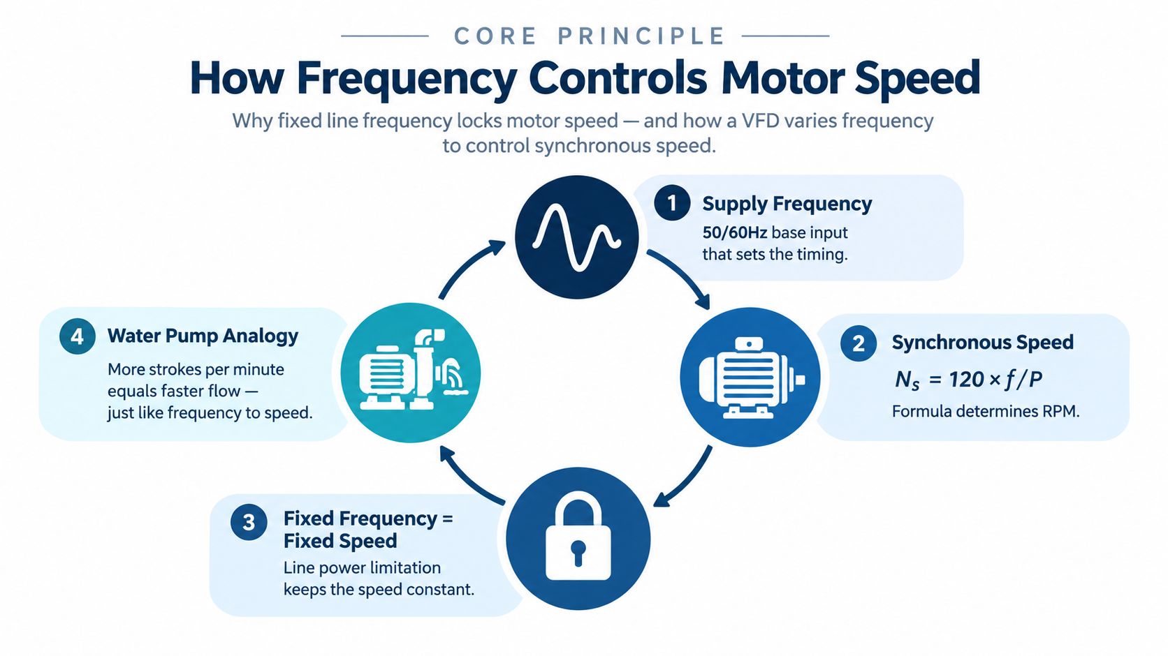
AC power isn't just energy. It has rhythm. The voltage rises, falls, reverses, and repeats in cycles. That cycle rate is the frequency. A motor's rotating magnetic field follows that electrical rhythm, so when the frequency changes, the motor's running speed changes with it.
Fixed line power means fixed speed tendency
A motor connected straight to the grid lives with the grid's timing. If the incoming supply stays fixed, the magnetic field pattern inside the motor also stays fixed in speed tendency. That's why a standard across-the-line motor usually runs at one practical operating speed for a given setup.
A simple analogy helps. Think of a reciprocating pump that takes strokes at a fixed pace. If the pump always makes the same number of strokes per minute, the flow pattern stays tied to that stroke rate. If you want less flow, you can partly close a valve, but the pump is still working at the same pace. To change output, you change the stroke rate itself.
A VFD does the electrical version of that. It changes the motor's “strokes per minute” by synthesizing a new output frequency.
The motor needs frequency and voltage to move together
Here's a point that causes trouble during commissioning. You can't usually change frequency alone and expect healthy motor behavior across the full operating range. As frequency changes, the drive also manages voltage so the motor's magnetic conditions stay usable.
If frequency drops too far without proper voltage control, torque behavior becomes poor and current can become troublesome. If frequency rises without the right voltage relationship, the motor may not develop the expected performance.
Key concept: Motor speed follows frequency, and the drive usually adjusts voltage with it so the motor can produce useful torque across the speed range.
What the VFD really does
The VFD breaks the hard link between utility frequency and motor frequency. The incoming grid remains fixed, but the drive builds a new output for the motor. That's the heart of the answer to how does a variable frequency drive work. It does not ask the utility to change. It converts and rebuilds power locally so the motor gets the frequency the application needs.
That's why a fan can ramp smoothly instead of snapping to full speed, and why a pump can settle where the process wants it rather than where the line frequency dictates.
Inside the Drive The Three Power Conversion Stages
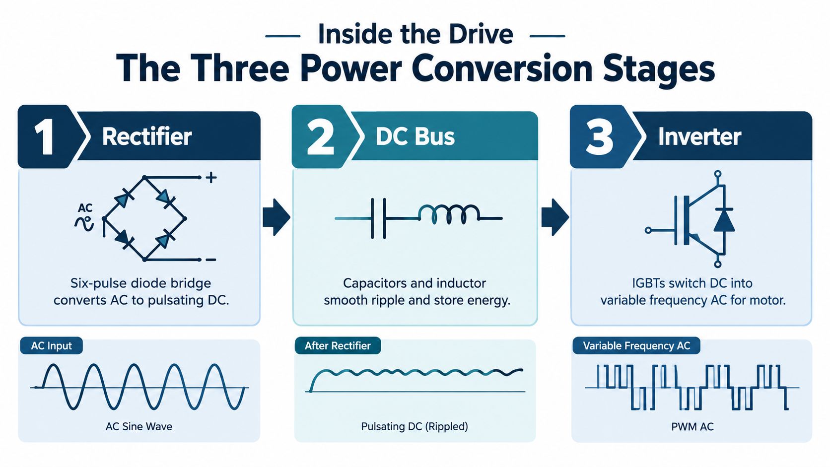
If you open the concept up one layer, the drive's job becomes easier to follow. It takes incoming fixed-frequency AC, converts it, stores and smooths it, then rebuilds it for the motor. According to Natural Resources Canada's explanation of variable frequency drives, a VFD works by converting fixed-frequency AC into DC in a rectifier stage, storing it on a DC bus, and then using high-speed semiconductor switching in the inverter stage to synthesize variable-frequency AC for the motor.
Rectifier stage
The first stage handles the incoming AC supply. In industrial drives, this front end is often a six-pulse bridge. Its job is straightforward. It converts AC to DC.
That DC is not perfectly smooth when it first appears. Think of it as power that has been redirected into one-way flow, but still carries ripple from the original AC source. If you scoped it here, you wouldn't see a clean flat line.
What matters in practice is that this stage separates the motor side from direct dependence on line frequency. The drive is starting to take control of the power rather than passing utility power through.
DC bus stage
The middle section is the DC bus. This is the energy reservoir of the drive.
The DC bus uses capacitors to smooth ripple and store energy. That smoothing matters because the inverter stage needs a stable DC source to create a controlled AC output. If the bus is unstable, the output quality suffers and faults become more likely.
This is also one reason bus health matters so much in older cabinets. When capacitors age, the drive may still power up, but the margin for stable operation shrinks.
A useful mental picture is a surge tank between an uneven upstream supply and a sensitive downstream process. The tank doesn't create final output by itself, but it gives the next stage something steadier to work with.
Inverter stage
The final power stage is where the drive earns its name. The inverter rebuilds AC from the DC bus.
In typical industrial designs, the inverter uses IGBTs and pulse width modulation, or PWM, to generate the output waveform. Those semiconductor switches turn on and off very quickly in a controlled pattern. The result is a pulsed output whose average effect behaves like variable-frequency AC to the motor.
Here's the field takeaway. The motor isn't being fed the same kind of smooth utility sine wave that came in at the line side. The drive is synthesizing a controllable output from fast switching events.
After the power path makes more sense, this short visual can help tie the hardware together:
<iframe width="100%" style="aspect-ratio: 16 / 9;" src="https://www.youtube.com/embed/wvzUE_Q9AhI" frameborder="0" allow="autoplay; encrypted-media" allowfullscreen></iframe>Why the DC link is the real dividing line
The most important architectural point is the decoupling. The rectifier and DC bus isolate the motor from fixed utility frequency, and the inverter creates a new electrical supply for the motor. That decoupling is what lets the drive regulate speed and torque by changing output frequency and voltage.
When troubleshooting, ask where the problem belongs. Is it on the incoming supply side, in the DC link, or in the inverter and motor path? That question saves time.
Control Methods That Shape Output Behavior
Two drives can have similar power hardware but perform very differently because their control method is different. On the plant floor, this matters more than many teams expect. It affects startup feel, low-speed behavior, speed holding, and how the drive reacts when the load changes.
V per Hz control
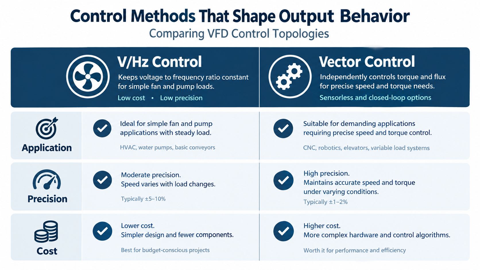
The simplest common method is V/Hz control. The idea is to keep voltage and frequency in step using a defined ratio.
For many fans and pumps, that's good enough. The load is usually forgiving, speed accuracy doesn't need to be razor sharp, and the process mainly needs stable adjustment rather than aggressive torque control. V/Hz setups are often chosen when the application is straightforward and the maintenance strategy favors simplicity.
What operators usually notice is that the drive runs the machine smoothly and predictably, but not with the same sharpness you'd expect in a demanding torque application.
Vector control
Vector control is used when the application needs tighter command of motor behavior. It treats torque and magnetic conditions more independently than a basic V/Hz approach.
That shows up in real work on conveyors, tensioned machinery, mixers under changing load, and other applications where the motor can't just drift along. Vector control helps the drive respond more firmly when the load changes or when low-speed torque matters.
Some setups use sensorless methods. Others use feedback devices for even tighter regulation. The key point for maintenance teams is simple. If the process depends on speed discipline or stronger torque response, the control method is part of the answer, not just the motor size.
Choosing VFD Control Method by Application Need
| Application Need | V/Hz Control | Vector Control |
|---|---|---|
| Simple fan or pump duty | Strong fit | Usually more than needed |
| General speed adjustment | Good fit | Good fit |
| Low-speed torque demand | Limited compared with vector | Better fit |
| Tight speed regulation | Basic | Better fit |
| Load changes quickly | Less responsive | More responsive |
| Setup simplicity | Simpler | More involved |
A more detailed practical comparison is available in this guide to VFD control methods.
What causes confusion during startup
A lot of “bad drive” complaints are really bad control matching. The drive powers the motor, but the machine feels weak, unstable, or too aggressive because the control mode doesn't fit the load.
Look at these clues during commissioning:
- Poor low-speed pull: Often points to setup or control choice, not only hardware trouble.
- Speed drift under changing load: More common when the application asks for tighter regulation than basic control can provide.
- Jerky response after parameter changes: May come from tuning choices rather than a damaged power stage.
Don't ask only whether the drive runs. Ask whether it runs the load the way the process requires.
Waveforms Signals and Power Quality in Real Operation
A drive can look healthy from ten feet away. The motor is turning, the keypad shows no fault, and production is moving. Then a technician puts a standard meter on the output, gets a strange voltage reading, and starts wondering whether the drive is failing. At the same time, an instrument panel on the same feeder begins acting erratically during heavy load.
That is real VFD operation on the plant floor. The simple block diagram explains power conversion, but it does not show what your test tools see, what the motor insulation sees, or what the rest of the electrical system has to live with.
What the motor-side signal really looks like
The inverter does not send out a clean utility sine wave. It builds an effective AC output by switching DC on and off very quickly with PWM, or pulse width modulation. The pulse pattern changes over time, so the motor responds to the average effect of those pulses as if it were seeing a controlled AC waveform.
A useful comparison is a valve being opened and closed very fast to control average flow. What matters at the load is not each individual snap of the valve, but the overall result across time. PWM works in a similar way, except the result is voltage and current delivered to the motor.
That is why output measurements cause so much confusion during commissioning and fault finding. A basic meter often assumes the waveform is sinusoidal. VFD output is not. The meter may report numbers that look unstable or do not answer the question you are asking.
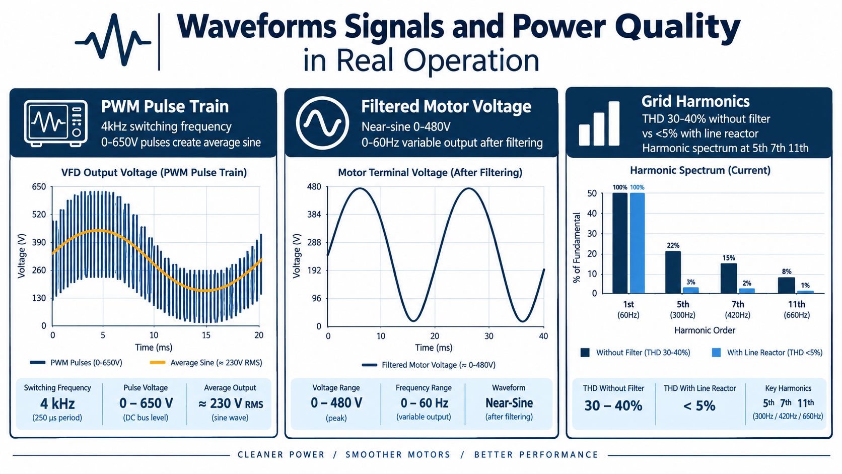
A scope trace, a true-RMS instrument rated for drive output, or the drive's own monitored values usually gives a more useful picture than a quick handheld voltage check. For maintenance teams, that point matters. Bad readings can send people toward the wrong repair.
The line side has its own story
The supply side also changes once drives are added. The rectifier section draws current in a non-sinusoidal way, so the plant distribution system can see harmonic currents, added heating in some components, and more electrical noise than it had with direct-on-line motors alone.
Many facilities treat harmonic limits at the point of common coupling as a practical design requirement, not an academic detail. A drive installation that runs the motor correctly can still create trouble upstream if line reactors, filtering, grounding, bonding, and cable routing were treated as afterthoughts.
Commissioning becomes more than a rotation check.
What technicians usually see in the field
The symptoms are often indirect. The drive itself may not fault at all. Instead, the wider system starts giving clues that waveform quality or installation practice needs attention.
Watch for patterns like these:
- Confusing output voltage readings: Common when the instrument is not suitable for PWM-rich waveforms.
- Sensitive devices reacting nearby: Instruments, transmitters, or control circuits may become erratic when electrical noise increases.
- Problems that appear under load: Distortion issues often show up more clearly when the drive is doing real work, not while idling at light load.
- Motor stress that does not match the nameplate story: Long motor leads, fast switching edges, and reflected-wave effects can raise insulation stress even when average voltage looks acceptable.
That last point is easy to miss. The motor does not experience only frequency and RMS voltage. It also experiences steep voltage transitions. On a long cable run, those transitions can matter a lot when you are deciding whether the problem is in the drive, the cable, or the motor.
Why this changes troubleshooting decisions
A technician who understands the waveform will test differently. Instead of asking only, “Is voltage present?” the better question is, “What kind of waveform is present, and is my instrument able to read it correctly?” Instead of replacing a drive because nearby equipment is acting up, the team checks grounding, shielding, reactor selection, cable separation, and the condition of the power system.
Good commissioning proves two things. The motor follows the command correctly, and the drive coexists properly with the plant electrical system.
A drive that runs the shaft but pollutes the feeder, confuses measurements, or stresses the motor insulation is not fully sorted. It is only partly understood.
Heat Contamination and Aging Inside Industrial Cabinets
Electrical theory explains how the drive works. Cabinet reality explains why drives fail.
A VFD switches power electronically, and switching creates heat. Even a healthy unit depends on clean airflow, working cooling fans, clear heat-sink paths, and components that still hold their electrical characteristics under temperature. Once those conditions slip, the drive may continue running for a while, but its margin gets thinner.
The cabinet is part of the drive system
Teams sometimes treat the cabinet as just a box around the drive. It isn't. The enclosure, filters, fan paths, cable entry points, and contamination level all influence reliability.
Dust buildup insulates hot surfaces. Conductive debris can create tracking risk. In harsh facilities, salinity and carbon black contamination can turn a cabinet into a slow electrical failure site rather than a protected environment.
Aging shows up first in the weak links
The parts that often age are the ones maintenance teams can't afford to ignore:
- Cooling fans: Airflow falls off long before a fan fully stops.
- DC bus capacitors: As they age, bus stability can become less forgiving.
- Power terminals and bus joints: Heat cycling can loosen or discolor connections.
- Filters and vents: If they load up with dirt, internal temperatures climb.
A shutdown inspection should look for more than obvious burn marks. Check airflow path condition, fan operation, dust patterns, terminal tightness, capacitor appearance, and signs of heat history on boards and buswork.
A drive that trips only in hot weather often isn't “mysteriously sensitive.” It may be telling you the cooling margin is gone.
Why preventive care changes repair decisions
If contamination and thermal stress are the root cause, swapping one failed part may only buy short time. The smarter choice may be cleaning, fan replacement, deeper inspection, and checking whether aging has already weakened the DC bus or output stage.
That's especially true on cabinets that live near process dust, salt-laden air, or carbon-heavy environments. The electrical fault may be the symptom. The cabinet condition is the disease.
Putting Knowledge to Work Commissioning Diagnostics and Repair Choices
When teams understand the drive as a power converter, control system, and cabinet heat source, troubleshooting gets more disciplined. You stop guessing and start isolating.
During commissioning, begin with the basics that shape behavior. Confirm motor data entry, control mode, direction, acceleration and deceleration behavior, interlocks, and fault response. Then look at actual operating conditions, not just successful no-load rotation. A drive that spins an uncoupled motor may still be badly set for the process. A practical reference for handover work is this VFD commissioning checklist.
A calm fault-isolation approach
When a drive trips, work the problem in layers:
- Input side: Check incoming supply quality and obvious front-end issues.
- DC link condition: Look for signs that bus stability, cooling, or aged components may be involved.
- Output and motor path: Check the inverter side, motor cable condition, motor health, and whether the control setup fits the load.
- Cabinet environment: Inspect contamination, airflow blockage, and thermal history before restarting repeatedly.
For larger assets, repair decisions also need logistics judgment. In some cases, on-site reconditioning is safer than transporting a medium-voltage unit that's already fragile. DUCHENG Industrial provides multi-brand commissioning, troubleshooting, repair, and on-site reconditioning for industrial VFD assets, which is one example of the kind of lifecycle support plants may use when restart risk and serviceability both matter.
Practical restart checklist
- Verify fault history: Read the sequence, not just the latest alarm.
- Inspect before reset: Check for contamination, fan failure, loose connections, and heat damage.
- Confirm settings: Make sure control mode and key parameters match the application.
- Test in stages: Bring the system back under controlled conditions before full process loading.
- Document handover: Record what changed, what was observed, and what still needs follow-up.
A VFD isn't difficult to understand once you connect the physics to what you see in the field. Frequency sets the pace. The drive rebuilds power to change that pace. Control strategy shapes behavior. Cabinet condition decides whether that behavior stays reliable.
If you're dealing with commissioning issues, recurring drive trips, or aging cabinets that need a more careful decision than simple replacement, DUCHENG Industrial provides lifecycle VFD services including commissioning support, troubleshooting, workshop repair, and on-site reconditioning. Their work is built around the exact realities covered here: power stages, control behavior, contamination, thermal stress, and controlled restart discipline.