
Explore industrial motor drive systems, from types and components to maintenance best practices. Make informed decisions for optimal performance and longevity.
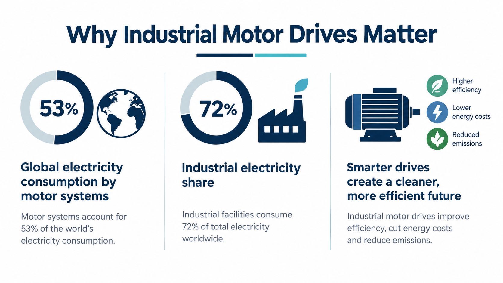
Electric motor systems consumed 13,462 TWh in 2023, equal to 53% of worldwide electricity consumption, and they accounted for 72% of industrial electricity use, according to the International Energy Agency's 4E motor-systems assessment. That scale changes how a plant should view an industrial motor drive. It isn't just a cabinet that varies motor speed. It's a power-conversion asset sitting between the electrical supply and a production system that may include pumps, fans, compressors, conveyors, extruders, rolling mills, or an entire process line.
A drive failure can stop production immediately. Poor setup can keep a motor running while increasing heat, harmonics, mechanical stress, or energy demand. The right maintenance decision is therefore rarely “repair or replace the drive” in isolation. It involves the motor, cable, load profile, cooling system, control strategy, spare-parts position, safety requirements, and the age of the installed fleet.
Table of Contents
- Why Industrial Motor Drives Matter More Than You Think
- How an Industrial Motor Drive Works From AC In to AC Out
- LV, MV, and HV Drives and Where Each One Fits
- Inside the Drive Components That Decide Reliability
- How to Choose the Right Drive Without Overselling It
- Common Failure Modes and What They Tell You
- Lifecycle VFD Services From Commissioning to Reconditioning
- A Practical Checklist and What Comes Next for Connected Drives
Why Industrial Motor Drives Matter More Than You Think
The 72% industrial share is the practical starting point. Motor-driven systems dominate industrial electricity use, so the condition of their motors, controls, driven equipment, and associated losses directly affects plant performance. The IEA assessment also reports motor-system shares of 36% in buildings, 87% in agriculture, and 86% in transportation, which shows how broadly electric motor systems influence electricity demand, but industrial sites face a particularly concentrated reliability problem. These figures include the complete motor system rather than only the motor or drive.
A drive gives operators control over speed, torque, acceleration, deceleration, current, and protective limits. That control can reduce throttling losses on a pump, prevent a conveyor from starting against a heavy shock load, or keep a process line within a stable operating range. It can also create new failure paths if the output waveform, motor insulation, grounding, cooling, or parameters don't match the installation.
The failure is usually bigger than the cabinet
A failed drive can interrupt a production train even when the motor itself is healthy. In a chemical plant, the drive may control a pump whose loss affects flow, pressure, temperature, or an interlock sequence. In a tire plant, a drive fault can stop a mixer, extruder, or conveyor and leave downstream equipment waiting. In steel, a drive problem can affect a rolling or handling system where restart conditions must be controlled carefully.
The same asset can also fail gradually. A cooling fan may lose capacity, a cabinet may collect conductive dust, or DC bus capacitors may age until the drive trips under a load that it previously handled comfortably. Maintenance teams that only respond to fault codes often replace the visible failed part without correcting the condition that caused it.
Practical rule: Treat the drive, motor, cable, load, and environment as one operating system. A reset is a recovery action, not a diagnosis.
The lifecycle decision starts before the first trip
A plant should record the drive's application, motor data, firmware and parameter set, cooling arrangement, fault history, and critical spare parts during commissioning. That record becomes essential when an aging drive must be restarted, repaired, reconditioned, or replaced under time pressure.
This guide follows that decision path. It starts with the power-conversion principles, then distinguishes voltage classes and components, examines failure clues, and closes with a service framework for choosing between continued operation, preventive work, deep repair, on-site reconditioning, and replacement.
How an Industrial Motor Drive Works From AC In to AC Out
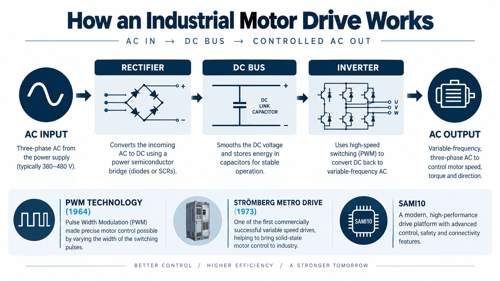
Modern PWM-based drives grew from power-electronics work in the 1960s. Historical accounts place sinusoidal PWM research in 1964, describe a PWM-drive concept sold for the Helsinki Metro in 1973, and identify the first SAMI10 PWM drives as operational in 1982. Vector-control concepts reported in 1972 further improved torque response and dynamic control, as summarized in this history of variable-frequency drives.
That history matters because a modern drive is far more than an electronic starter. It converts electrical power, synthesizes a new waveform, measures current and voltage, applies protection, communicates with automation systems, and responds to the mechanical behavior of the load.
The four stages of the power path
Draw the power section from left to right:
- AC input. The plant supply enters through switching, protection, and often an input reactor or harmonic-mitigation arrangement.
- Rectifier. The rectifier changes incoming AC into DC. Depending on the design, it may be a diode, thyristor, or active front end.
- DC bus. Capacitors smooth and store energy between the rectifier and inverter. Precharge circuits and monitoring protect this section during energization.
- Inverter. Semiconductor switches create a controlled three-phase output. PWM changes the switching pattern so the motor sees the required effective voltage and frequency.
The motor doesn't receive a clean utility waveform in the traditional sense. It receives a sequence of switched voltage pulses whose fundamental component produces the desired magnetic field. The output cable, motor construction, grounding, and switching behavior all affect the final result.
Frequency controls speed, but torque needs control logic
Consider an induction motor driving a pump. At lower process demand, the drive reduces output frequency and voltage while maintaining an appropriate volts-per-hertz relationship. That keeps magnetic flux within a usable range and lets the motor operate below full speed without wasting energy across a valve or damper.
Speed control and torque control aren't identical. A basic volts-per-hertz strategy is often suitable for a pump or fan with a predictable load. A conveyor, extruder, or rolling application may need vector control, encoder feedback, torque limits, braking management, or a carefully tuned acceleration profile. The correct mode depends on what the process demands during starting, steady operation, speed changes, and stopping.
<iframe width="100%" style="aspect-ratio: 16 / 9;" src="https://www.youtube.com/embed/m5JYkgCRbBI" frameborder="0" allow="autoplay; encrypted-media" allowfullscreen></iframe>When a drive is repaired or replaced, technicians shouldn't copy parameters blindly. They need to verify motor nameplate data, control mode, minimum and maximum speed, current limits, ramp times, braking settings, feedback configuration, fault actions, and the process permissives that govern a safe restart.
LV, MV, and HV Drives and Where Each One Fits
Voltage class determines far more than the rating printed on the cabinet. It affects semiconductor selection, insulation coordination, clearances, cooling, enclosure design, arc-flash boundaries, test methods, transport, and the practical service plan.
Low-voltage drives
Low-voltage drives, commonly used up to around 690 V, are the most familiar class in general manufacturing. They control pumps, fans, compressors, conveyors, machine tools, mixers, and auxiliary systems. Compact transistor-based inverter sections, often built around IGBT technology, make LV systems flexible and widely serviceable.
Their advantages are straightforward. Cabinets are relatively compact, replacement units are easier to handle, and workshop repair is usually practical. The trade-offs appear in high-current applications, long motor cables, harsh environments, and sites with weak power systems. Input harmonics, reflected-wave stress, leakage current, and cooling contamination still need engineering attention.
Medium-voltage drives
Medium-voltage drives, often applied across roughly 2.3 to 13.8 kV, serve larger motors and continuous-duty processes. They may use multilevel inverter arrangements, cell-based power sections, isolation transformers, harmonic filters, and more elaborate cooling and protection systems.
A single MV drive can contain many subsystems that must be tested together. Shipping may introduce lifting, packaging, insurance, and schedule risks, especially when the drive is large or integrated into a critical process. For background on the class and its applications, see this medium-voltage drive resource.
High-voltage arrangements
High-voltage applications belong to heavy-industry and utility-scale environments where power, insulation, switching, and safety requirements become dominant design factors. The exact boundary varies by application and jurisdiction, so the plant's electrical standard and equipment documentation should govern the classification.
| Class | Typical plant position | Main service trade-off |
|---|---|---|
| Low voltage | General machinery, pumps, fans, conveyors, compressors | Easier handling and replacement, but sensitive to installation quality, heat, dust, and cable effects |
| Medium voltage | Large pumps, fans, compressors, mills, and continuous processes | More complex testing and safety controls, often favoring on-site repair or reconditioning |
| High voltage | Heavy industrial and utility-scale motor systems | Highest insulation, protection, and specialist service demands |
The lifecycle consequence is important. An LV drive may justify holding an exchange unit. An MV or HV drive may justify a detailed condition assessment, an on-site reconditioning plan, and verified subsystem spares long before failure.
Inside the Drive Components That Decide Reliability
A service report becomes more useful when each symptom points to a subsystem. The drive is a chain, and the weakest link can be upstream of the fault code.
The power section
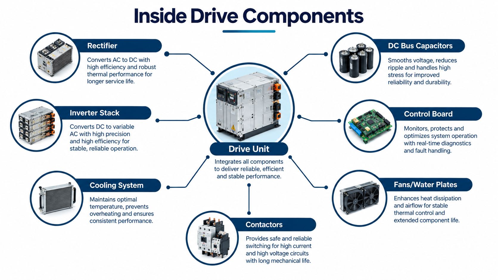
The rectifier handles the incoming supply and can suffer from semiconductor damage, input imbalance, overvoltage, or poor upstream switching conditions. A recurring input fault calls for supply measurements and inspection of fuses, contactors, reactors, and connections, not just replacement of the rectifier module.
The DC bus capacitors smooth the rectified supply and absorb ripple current. Their condition can deteriorate gradually. Increased ripple, abnormal bus behavior, nuisance trips, or reduced load tolerance may indicate capacitor aging even when the drive still starts. Replacing capacitors without checking temperature, ventilation, and ripple conditions often produces a temporary fix.
The inverter stack switches the DC bus into the motor waveform. Semiconductor short circuits, gate-driver faults, loose bus connections, and insulation problems can cause overcurrent or ground-fault trips. A technician needs controlled resistance checks, gate-signal verification, insulation testing where appropriate, and a careful review of the motor circuit before energizing a repaired stack.
Control, cooling, and human interfaces
The control board manages measurement, protection, communications, and parameter storage. Its failures may look like software, network, feedback, or parameter problems. Preserve the parameter set before changing boards, and verify compatibility across firmware, option cards, feedback devices, and power-section revisions.
Cooling is not an accessory. Fans, filters, heat sinks, water plates, thermal sensors, and cabinet airflow determine how much heat the power devices can reject. Dust, humidity, salt, carbon contamination, and blocked passages raise thermal stress. A fan alarm may be the final warning after weeks of declining airflow.
Contactors and precharge circuits also deserve attention because failed sequencing can expose the DC bus to damaging inrush. The HMI and communication interfaces provide useful evidence, but their displayed fault is only one part of the investigation.
The component that trips is not always the component that failed first.
A good maintenance record connects the drive's environment and operating duty with measurements from the rectifier, bus, inverter, control system, and cooling path. That connection determines whether the next action is cleaning, component replacement, workshop repair, reconditioning, or a planned changeout.
How to Choose the Right Drive Without Overselling It
Start with the load, not the motor nameplate. A drive selected only from voltage and horsepower can run the motor while missing the process requirements that determine energy use, thermal behavior, braking, and service life.
For pumps and fans, affinity-law behavior means shaft power is approximately proportional to the cube of speed. Reducing speed to 80% can theoretically reduce shaft power to about 51% of full-speed power, before motor, drive, and system losses are included. In practice, independent energy analysis reports typical VFD savings of roughly 5% to 15% across applicable installations, while individual applications have reported 20% to 65%, depending on duty cycle, throttling losses, static head, and operating hours.
Build the decision from measured duty
Record flow, pressure, speed, run hours, actual electrical demand, valve or damper position, bypass operation, and process limits. Compare the existing operating method with the proposed speed-control strategy across the duty cycle. A drive may reduce energy use substantially in a variable-torque application, but it won't create savings if the process still requires constant speed or if minimum speed is set unnecessarily high.
Check these selection questions before approving the specification:
- Load behavior: Is the application variable torque, constant torque, or a demanding regenerative load?
- Motor compatibility: Can the motor tolerate the proposed waveform, cable length, insulation stress, and low-speed thermal duty?
- Power quality: Will the drive's input arrangement create a problem for the plant supply, or does the installation need filtering or a different front end?
- Environment: Are enclosure protection, cabinet cooling, humidity control, dust management, and altitude requirements documented?
- Control needs: Does the process need volts-per-hertz, sensorless vector, closed-loop feedback, position control, braking, or coordinated motion?
- Lifecycle support: Are parameter backups, test procedures, exchange parts, and multi-brand service capabilities available?
| Class | Voltage range | Typical applications | Key selection notes |
|---|---|---|---|
| LV | Up to about 690 V | Pumps, fans, conveyors, compressors, machinery | Check current, cable effects, cooling, harmonics, and spare strategy |
| MV | Roughly 2.3 to 13.8 kV | Large pumps, mills, compressors, continuous processes | Assess cell or multilevel topology, transformer needs, safety, and on-site service |
| HV | Above common MV ranges | Heavy industrial and utility-scale systems | Confirm insulation, protection, specialist testing, and restoration arrangements |
A VFD is the wrong answer when the process requires constant speed, the motor isn't suitable for the waveform, or the proposed control scheme merely moves energy losses elsewhere. A measured baseline protects the project from an attractive theoretical calculation that doesn't survive commissioning.
Common Failure Modes and What They Tell You
A drive trip is a system event. The fault log tells you where the control system noticed abnormal behavior, but it doesn't automatically identify the initiating condition.
Electrical clues
Overcurrent can originate in the motor, cable, mechanical load, acceleration profile, or inverter. Ground faults may involve insulation breakdown, contamination, cable damage, or motor terminal issues. DC-bus overvoltage can follow deceleration, regenerative energy, supply disturbance, or braking-system problems.
Bearing-current damage is a particularly important example. PWM switching can create common-mode voltage between motor windings and ground. Parasitic capacitances couple that voltage to the rotor, creating shaft voltage and a return-current path through the bearings. The resulting electrical discharge machining events can damage raceways and rolling elements, degrade lubrication, and produce fluting or washboard-pattern marks, as described in this review of bearing-current mechanisms and mitigation.
When this pattern appears, inspect the output waveform, motor-frame bonding, cable-screen termination, shaft voltage, and bearing-current path. Possible mitigations include a correctly selected common-mode or sine-wave filter, symmetrical low-impedance grounding, suitable shield termination, insulated bearings, or a shaft-grounding brush. These measures must be coordinated with the drive and motor manufacturer because filtering changes leakage current, reflected-wave stress, and EMC behavior.
Thermal and mechanical clues
Thermal aging often develops inside a cabinet before the drive produces a hard trip. Contaminated filters, blocked heat sinks, failing fans, high ambient temperature, and loose power connections all raise temperature. Trending cabinet temperature, fan operation, bus behavior, and load current during planned inspections gives the team more time than waiting for an overtemperature alarm.
Mechanical symptoms can start outside the drive. A pump operating away from its stable region, a conveyor with increased friction, or a compressor with process resistance can increase current and trigger protection. Vibration monitoring remains useful, but it shouldn't replace electrical checks when a PWM-fed motor shows repeated bearing or insulation problems.
Read the fault in context. A repeated overcurrent at acceleration points toward a different investigation than an overcurrent after hours of rising cabinet temperature.
Separate the immediate symptom from the initiating cause. Then decide whether the corrective action is parameter adjustment, cooling restoration, cable or motor repair, bearing-current mitigation, component replacement, or a broader reconditioning project.
Lifecycle VFD Services From Commissioning to Reconditioning
Lifecycle service works best when each intervention has a defined purpose. Commissioning establishes a trustworthy baseline. Rapid restoration protects production after an unexpected fault. Preventive care reduces avoidable stress. Deep repair and reconditioning address assets that still have useful life but need controlled renewal.
Match the service tier to the operating problem
Commissioning and production escort should confirm rotation, motor data, control mode, ramp behavior, feedback, protective limits, interlocks, and restart conditions. A controlled restart after a fault should preserve evidence, record the original alarm state, and verify the motor and load before repeated resets.
Rapid restore is appropriate when production is down and the plant needs structured on-site diagnosis. The objective isn't just to clear the trip. It is to isolate the fault, identify safe temporary measures where permitted, and return the equipment to service without hiding a repeat-failure mechanism.
Deep workshop repair suits LV and selected MV equipment that can be removed safely. Disassembly, bench diagnostics, component-level repair, board and power-section testing, thermal inspection, and functional tests provide more control than changing parts on the production floor.
Preventive care belongs in planned shutdowns. Cleaning, airflow verification, terminal inspection, capacitor and fan assessment, parameter backup, thermal checks, and review of the fault history can expose aging before it becomes a production event.
For large MV and HV systems, on-site blue reconditioning can be more practical than shipment. The team can work through power cells or modules, auxiliaries, cooling, control systems, insulation-related checks, and functional verification within the plant's controlled outage window. That approach reduces transport exposure and keeps the restoration plan connected to the actual installation.
Decide whether to ride out, renew, or replace
Continue operating an aging drive when condition data is stable, spares and documentation are available, the application remains compatible, and the consequence of failure is covered by a credible recovery plan. Recondition when the chassis, topology, motor interface, and control architecture remain suitable but components, cooling, contamination, or aging auxiliaries create unacceptable risk.
Replace when the drive is obsolete without support, repeatedly fails after corrective work, cannot meet process or safety requirements, or lacks a viable secure control path. An upgrade assessment should test whether serviceable subsystems can be renewed before recommending whole-unit changeout.
An industrial drive service program should define scope, outage duration, test evidence, warranty boundaries, parameter ownership, and the exact conditions for restart. Energy projects also need the same discipline. An assessment of more than 10,500 motor-driven systems conducted from November 2024 to May 2025 prioritized 5,900 systems and identified average energy savings of 43% among those prioritized, according to this motor-system energy assessment. That is an assessed opportunity, not a guaranteed retrofit result. Baseline quality and duty cycle still decide the actual outcome.
A Practical Checklist and What Comes Next for Connected Drives
Before commissioning, verify motor data, load profile, control mode, cable and grounding design, cooling, protective limits, parameter backup, and restart logic. Before repairing, preserve the fault history, inspect the motor and cable, check the environment, and confirm whether the same failure has occurred before. Before replacing, compare repair, reconditioning, upgrade, spare, and whole-unit options against process criticality and supportability.
For connected drives, define what data leaves the OT environment and who owns credentials, firmware, backups, gateways, and incident response. Segment legacy equipment, use least-privilege access and MFA at gateways, prohibit direct internet exposure, collect read-only data where possible, and maintain a manual fallback when communications fail.
The security burden is already operational. In 2025, industrial-control-system advisories exceeded 500, covered 2,155 CVEs, and had average severity above 8.0 on the CVSS scale, with critical manufacturing and energy among the most affected sectors, according to this industrial-control security report. A legacy drive that can't support modern controls doesn't automatically require premature replacement. Segmentation, allowlisting, jump-host access, read-only monitoring, offline parameter backups, and planned renewal can reduce exposure while preserving production continuity.
DUCHENG Industrial supports industrial motor-drive lifecycles through multi-brand commissioning, troubleshooting, preventive maintenance, workshop repair, spare-parts verification, and on-site medium- and high-voltage reconditioning. Review your drive fleet and service options with DUCHENG Industrial, especially before a planned shutdown or when repeated trips are forcing a repair-versus-replace decision.