
Design and run an industrial preventive maintenance program that cuts downtime. Covers VFD checks, schedules, contamination control, and spare parts.
A rolling line doesn't care that the maintenance schedule looked healthy yesterday. When a medium-voltage drive trips, production can stop with little warning, and the repair rarely ends with replacing one failed component. A breaker may open, the inverter may latch a fault, operators may wait for electrical isolation, and the team may discover that the correct control card or power module isn't on site.
That's why industrial preventive maintenance has to be built around actual drive failure modes, not generic checklists. Cabinet contamination, heat-stressed capacitors, degraded fans, loose power terminals, incompatible spare boards, and aging gate-driver circuits all leave clues before they become a line-stopping event. The useful program is the one that captures those clues, assigns someone to act on them, and protects a realistic shutdown window for the work.
Table of Contents
- Why Industrial Preventive Maintenance Pays Off
- Designing the Program Around Your Critical Assets
- Choosing the Right Maintenance Strategy Mix
- VFD and Drive-Specific Inspection Tasks
- Handling Contamination, Heat Aging, and On-Site Reconditioning
- Spare Parts Identification and Pre-Dispatch Verification
- Launching the Program and Avoiding Common Pitfalls
Why Industrial Preventive Maintenance Pays Off
At a steel plant, a 1.5 MW medium-voltage drive trips during a rolling campaign. The input breaker opens, the inverter fault remains latched, and the line stays down while the crew searches for a spare control card. An OEM callback takes hours, and the repair window expands because the team must diagnose the drive before ordering the right part. By the time production restarts, a fault that might have been handled during a planned outage has become an operational and procurement emergency.
The failure often begins without warning. A cooling fan loses airflow, cabinet dust restricts heat transfer, or DC-link capacitors begin to swell and lose electrical margin. A thermal scan, fan inspection, and capacitor trend taken weeks earlier could have converted that event into a scheduled intervention.
Industrial maintenance has become mainstream, but labor allocation still lags behind adoption. A 2024 global industrial maintenance report found that 86.8% of facilities reported active preventive maintenance use, while nearly 60% dedicated less than half of total maintenance time to it. The same report recorded an average of 33 hours per week on scheduled maintenance, up from 20 hours in 2020. Plants are scheduling more work, yet many still don't give the program enough labor to produce reliable findings.
The economic reason to plan
The historical argument is straightforward. Preventive maintenance replaced the old habit of repairing equipment only after failure because failure-driven work disrupts production, consumes premium labor, and creates safety exposure. Research from the U.S. National Institute of Standards and Technology estimated $119.1 billion in losses from preventable maintenance issues in 2016, including $18.1 billion from downtime and $100.2 billion from lost sales caused by delays and defects.
The same research found that manufacturers relying more on predictive than preventive maintenance experienced 18.5% less unplanned downtime and 87.3% fewer defects. Those figures don't mean every plant should install sensors on every drive. They show why disciplined preventive work became the foundation for more advanced reliability programs.
| Metric | Reactive, run-to-failure | Preventive program |
|---|---|---|
| Work timing | After the trip or failure | During a controlled maintenance window |
| Parts decision | Often made under pressure | Based on asset records and compatibility checks |
| Labor | Troubleshooting, escalation, and overtime may coincide | Planned electrical, mechanical, and automation resources |
| Drive risk | Fan, capacitor, contamination, and connection defects remain hidden | Known failure indicators receive inspection and follow-up |
| Production exposure | Operations absorb an unplanned outage | Operations can plan access and restart testing |
A preventive program doesn't eliminate every breakdown. It does create a better choice between a controlled shutdown and an outage governed by the fault, the storeroom, and the next available specialist.
Designing the Program Around Your Critical Assets
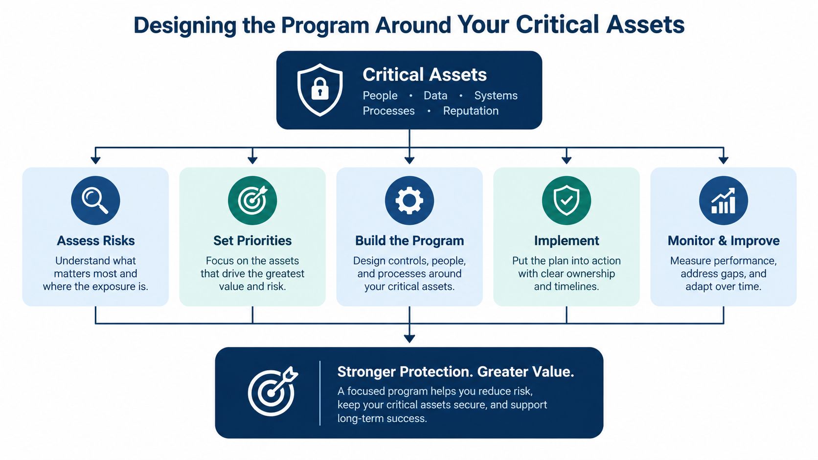
A useful program starts with decisions, not forms. Rank the assets first, then set intervals, define tasks, assign ownership, and design records that let the team see deterioration.
Start with criticality
Use a simple A, B, and C matrix:
- A assets affect a major production constraint, create significant safety risk, or require a complex restart. A main rolling-line MV drive belongs here.
- B assets can reduce throughput or cause a difficult repair, but the plant has a practical bypass, parallel unit, or shorter recovery path.
- C assets have limited production and safety impact, with accessible spares and straightforward replacement.
Score each drive against production loss per hour, safety consequence, repair complexity, spare lead time, and restart dependency. Don't let nameplate power decide criticality by itself. A smaller LV drive feeding an essential cooling or lubrication system may deserve more attention than a larger unit with a ready standby.
Select intervals by failure mechanism
Calendar intervals should reflect what ages. Electrolytic capacitors may need focused review around 5 to 7 years, while cooling fans commonly deserve replacement planning around 3 to 5 years. Contactors are better tied to their operating history, with 100,000 operations as a stated reference point in the work plan rather than an automatic guarantee. Thermal pads should be inspected for compression, drying, or poor contact instead of being replaced blindly.
The interval also needs a condition component. A dirty coastal cabinet may need attention sooner than a sealed indoor panel, and a drive operating near its thermal limit won't age like a lightly loaded unit.
Define tasks and owners
Make each task observable. “Inspect VFD” is weak. “Record rectifier temperature, photograph the DC bus, verify fan airflow, and flag any abnormal terminal temperature” gives the technician a usable decision path.
Assign ownership by trade:
- Electrical technicians handle cabinet internals, power connections, insulation checks, and capacitor measurements.
- Mechanical technicians inspect fan bearings, heat sinks, louvers, and airflow paths.
- Automation engineers verify firmware, parameter backups, encoder feedback, communications, and restart logic.
- The planner or reliability engineer reviews findings, changes intervals, and closes the loop with operations.
Practical rule: A PM task isn't complete when someone ticks a box. It's complete when the recorded result supports a repair, a deferral, or a justified return to service.
Build records that reveal change
Capture torque values, thermal images, load conditions, firmware versions, parameter backups, fan runtime, capacitor readings, and replacement-batch serial numbers. Record the instrument and test state when it matters, especially whether the drive was cold, loaded, or recently restarted.
A record should connect the component to the parent asset. “Fan replaced” isn't enough. The useful entry identifies the drive, fan part number, runtime or observed condition, technician, date, and reason for replacement. Trends become valuable only when technicians record comparable readings in a consistent format.
Choosing the Right Maintenance Strategy Mix
No single strategy fits every drive subsystem. A fixed-interval PM is easy to schedule, condition-based work responds to measured evidence, and predictive maintenance uses trends to anticipate deterioration. The right mix depends on failure criticality, observability, data quality, and the cost of accessing the asset.
A fixed-interval policy can outperform purely corrective maintenance. One recent study reported about a 7% reduction in expected total maintenance cost, more than 25% lower critical failure-driven maintenance expenditure, and fewer urgent interventions and total maintenance visits after moving to fixed-interval preventive work. The study on fixed-interval preventive maintenance also identified the main trap: intervals set too long allow failure-driven costs to rise faster than planned-maintenance savings.
Match strategy to the component
Fixed-interval maintenance works well for wear-dominated parts such as fans, contactors, filters, and known capacitor aging risks. It doesn't require complex infrastructure, but it can waste labor on healthy equipment and may miss failures that develop between visits.
Condition-based maintenance is stronger for thermal and vibration-observable problems. A temperature rise, unusual fan vibration, or changing current balance can trigger inspection without forcing replacement on a calendar date. The weakness is practical. Sensors need coverage, thresholds need tuning, and someone must respond to the alert.
Predictive maintenance suits high-value inverters where historians, sensors, and failure records already exist. It can identify a trend earlier than a periodic inspection, but data collection isn't the hard part. The hard part is converting the data into a reliable maintenance trigger and assigning a person to act.
Comparative research reported that moving from corrective to preventive maintenance improved MTBF by about 15% and reduced MTTR by about 10%, with a life-cycle-cost reduction of roughly 8% to 10%. Moving further to predictive maintenance added another 20% MTBF improvement and 15% MTTR reduction, with up to an additional 12% to 18% life-cycle-cost reduction, according to this maintenance-strategy comparison.
| Strategy | Cost profile | Failure detection lead time | Best fit |
|---|---|---|---|
| Fixed interval | Predictable labor and parts demand | Planned interval only | Fans, filters, contactors, known wear mechanisms |
| Condition based | Inspection and monitoring cost follows asset need | Depends on measurement frequency | Thermal, vibration, and airflow problems |
| Predictive | Higher data and analysis burden | Potentially earlier through trend change | High-criticality inverters with usable sensor history |
A practical starting point is simple: use fixed intervals for safety-critical and wear-dominated parts, condition checks for measurable thermal and vibration behavior, and predictive analysis only where the plant already has trustworthy data.
Don't promise savings before you have a baseline. Measure failure count, downtime, MTBF, MTTR, emergency work, and maintenance hours by asset class, then change one part of the strategy and review the result.
VFD and Drive-Specific Inspection Tasks
A VFD inspection should answer one question: what evidence says this drive can carry its next operating window safely? Generic visual checks miss the components that fail under load, heat, contamination, and vibration.
Start with the cabinet energized only when the procedure, arc-flash controls, and operating conditions allow it. Thermal imaging is most useful at a repeatable load state. Scan the rectifier, DC bus connections, IGBT modules, heatsinks, input and output terminals, and any line reactor or braking components. Record ambient temperature, load, image location, and the difference from comparable phases or previous scans.
Use intervals that produce trends
A workable inspection rhythm includes:
- Monthly: thermal scans, filter condition, cabinet temperature, fan alarm status, and visible contamination.
- Quarterly: fan runtime and bearing condition, terminal torque verification during an approved outage, airflow checks, encoder feedback, and fiber-optic link condition.
- Annually: DC-link capacitance and ESR trending, insulation-related checks as appropriate, parameter backup verification, and a deeper review of age-sensitive components.
Acceptance criteria must match the manufacturer and application. As an example of a site-defined screening rule, a heatsink may be required to remain below a 30 °C delta-T above ambient at rated load, while a DC-link capacitor may be flagged when measured capacitance falls below 80% of nameplate. Those are not universal pass limits. Put the governing value in the work instruction and document why it applies.
What to inspect inside the drive
Thermal condition comes first because heat accelerates several failure modes at once. Compare phases, modules, and repeated scans. A single hot connection can point to looseness or rising resistance, while a uniformly high heatsink temperature may indicate airflow loss, blocked passages, overload, or derating failure.
Contamination deserves a scored record. Use a 1 to 5 contamination scale defined by the site, from clean surfaces to deposits that obstruct airflow or bridge insulation paths. Photograph the cabinet and PCB condition, then record filter state rather than writing “dirty.”
DC-link capacitors need trend data, not a one-time pass. Record capacitance, ESR where the test method supports it, visual swelling, leakage evidence, and installation batch. A falling trend is more useful than an isolated reading because it supports planned replacement before ripple current and bus instability create trips.
Fans and airflow require more than listening. Record runtime, bearing noise, rotation, alarm status, and airflow at the intended path. Check that the fan cools the module and that a failed auxiliary circuit can't leave the drive apparently powered while the heatsink receives no usable airflow.
Connections and feedback are equally important. Verify power and control terminal torque using the approved tool and value. Check encoder feedback, fiber-optic cleanliness and seating, shielding, and parameter consistency. A drive can have healthy power electronics and still trip because feedback or communication integrity has degraded.
A digital preventive maintenance checklist for industrial assets is useful only if it requires readings, images, findings, and follow-up work instead of a completion tick.
Use the following matrix as a starting structure, then replace example limits with approved site values.
| Inspection task | Subsystem | Interval | Acceptance criterion |
|---|---|---|---|
| Thermal scan | Rectifier, DC bus, IGBT heatsinks, terminals | Monthly | Stable trend, balanced phases, and site delta-T limit met |
| Contamination score | Filters, cabinet, PCBs | Monthly | Score within site limit, no blocked airflow or conductive deposits |
| Fan check | Cooling assembly | Quarterly | Correct runtime, airflow, rotation, and no abnormal bearing noise |
| Terminal torque | Power and control connections | Quarterly outage | Approved torque value recorded, no heat damage or looseness |
| Feedback verification | Encoder and fiber links | Quarterly | Clean signal, secure connections, no intermittent fault history |
| Capacitance and ESR trend | DC-link capacitors | Annual | Above approved replacement threshold and stable against prior readings |
The embedded video below can help technicians visualize a drive inspection sequence, but it shouldn't replace the plant's electrical safety procedure or OEM-specific instructions.
<iframe width="100%" style="aspect-ratio: 16 / 9;" src="https://www.youtube.com/embed/dAF-c1WafmM" frameborder="0" allow="autoplay; encrypted-media" allowfullscreen></iframe>Handling Contamination, Heat Aging, and On-Site Reconditioning
Contamination and heat are coupled problems. Dust restricts filters and heatsinks, salt can create conductive deposits, carbon black can settle across electronics, and poor airflow raises component temperature. The drive may continue running while its remaining thermal margin disappears.
Cabinet control starts with the enclosure. Check door seals, gland plates, cable entries, louvers, and pressure condition. Where the application permits, positive pressurization with clean instrument air can reduce ingress, but it needs controlled pressure, dry air, suitable filtration, and a documented failure response. Don't assume a pressurized cabinet is protected if the door seal is damaged or the air supply is wet.
Replace filters by condition
Calendar replacement is easy to administer but often poorly matched to site conditions. Use differential pressure, airflow, contamination score, and operating environment to decide when a filter needs attention. A filter that looks acceptable from the outside may be loaded on the intake face, while a filter that is changed too often wastes labor without improving protection.
PCB cleaning requires discipline. Isolate the drive, follow the discharge and lockout procedure, use ESD-safe vacuum equipment, and use compatible cleaning materials such as approved IPA where the board and manufacturer instructions allow it. Don't blast dust deeper into connectors or use uncontrolled compressed air across sensitive components.
Control thermal aging
Inspect heatsink passages, fan direction, derating assumptions, and cabinet temperature. Confirm that a cooling fan isn't powered from the same circuit it is supposed to protect. If that auxiliary supply fails with the drive's main control supply, the drive can lose cooling while alarms or diagnosis become unreliable.
Medium-voltage drives deserve a planned mid-life review. On-site reconditioning can include module removal, thermal-paste renewal, capacitor reforming or replacement, gate-driver board inspection, connector examination, and a controlled insulation test. The exact sequence depends on the drive design and approved procedures, but the principle is consistent: restore serviceable subsystems during a controlled outage instead of waiting for a catastrophic failure or shipping a large assembly without a diagnosis.
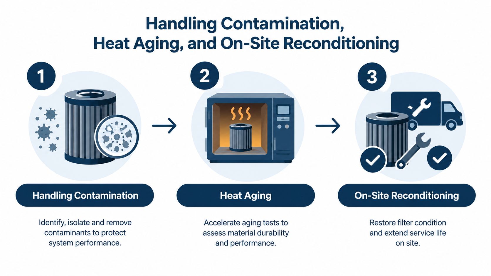
Shutdown discipline: Consumables, torque tools, test equipment, lifting equipment, replacement modules, and drawings must be staged before the outage starts. An outage is not the time to discover that the correct lifting arrangement or thermal compound isn't available.
A reconditioning plan should include acceptance tests, torque records, photographs, insulation results, parameter backup, controlled energization, no-load checks, loaded operation, and operator handover. If the drive serves a process with stored energy or hazardous materials, coordinate the restart with operations and process safety personnel. A technically correct repair can still become a plant incident if the restart sequence is improvised.
Spare Parts Identification and Pre-Dispatch Verification
A spare is only useful when it is compatible, available, and ready to install. A box labeled “VFD control board” doesn't meet that standard. The board may belong to the wrong revision, contain different firmware, use another connector pin-out, or require a gate-timing arrangement that the parent drive doesn't support.
Build the spare list from criticality and failure consequence. For a high-criticality drive family, consider holding one compatible control board, IGBT modules matched to the drive revision, fan assemblies by exact part number, and a matched DC-bus capacitor set sized for the panel's actual configuration. Don't create a blanket list for every drive in the plant. Identify which assets have no bypass, long procurement risk, or difficult restart requirements.
Verify compatibility before purchase
The compatibility review should compare:
- Drive family and revision, including hardware suffixes and board variants.
- Firmware revision, parameter structure, and any required migration process.
- Connector pin-out, harness arrangement, optical interface, and mounting details.
- Power-module specification, gate-driver pairing, voltage class, current rating, and revision.
- Capacitor characteristics, including capacitance, voltage, ripple capability, dimensions, and terminal arrangement.
- Application constraints, such as motor data, encoder type, braking arrangement, and control architecture.
A newer module isn't automatically a drop-in replacement. Changes in gate timing, protection behavior, or board communication can create a second failure after installation. Have engineering approve substitutions and preserve the compatibility decision with the asset record.
Test the part before dispatch
Pre-dispatch checks should happen before the part leaves the storeroom or workshop. Inspect packaging and connectors for storage damage, test capacitor capacitance and leakage under the approved procedure, and bench-power boards where safe and technically possible. For exchange units, record the test result and attach photographs.
Match the physical serial number and revision against the work order. Photograph the label, connector side, and packaging, then compare those images with the requested asset. This small control prevents a familiar failure pattern, the right-looking part being sent to the wrong drive.
Tag every spare with its parent asset tag, not only a generic description. Record the part number, revision, firmware state, storage condition, test date, and location. Guidance on industrial asset management and maintenance records can help structure that relationship, but the operating rule is simple: every spare must point to the equipment it can actually restore.
Launching the Program and Avoiding Common Pitfalls
Roll out the program in waves rather than publishing hundreds of PMs that the crew can't execute. Start with one critical drive line for a defined pilot period, refine the work instructions from technician findings, expand to the remaining VFD and MV assets, and bring rotating equipment into the same reliability system only after the electrical program produces consistent data.
Assign one owner per asset class. The electrical reliability owner should control drive task quality, the automation owner should protect parameters and firmware records, and a central CMMS owner should enforce naming, failure codes, closure notes, and asset relationships. Without data ownership, the program becomes a collection of completed work orders that can't support decisions.
Avoid the traps that make PM look successful
KPI worship creates false confidence. MTBF on a small fleet can fluctuate because one event changes the average dramatically. Use MTBF and MTTR as decision aids, not as proof that every PM task is effective.
Checklist drift happens when technicians repeat last year's steps without comparing them with actual failures. If a recurring trip is caused by a loose auxiliary connection but the checklist only asks whether the cabinet is clean, the program is busy rather than useful.
Parts hoarding can hide a sourcing problem. Stocking every board and module ties up capital and still may not produce compatibility. Link each stocked part to a critical asset, a justified failure mode, and a verified replacement path.
Over-scheduling causes crews to bypass work. A PM that takes longer than the available access window will be rushed, deferred, or closed without proper findings. Set frequencies that reflect risk and execution capacity, then change them when evidence changes.
Run a short quarterly audit
A maintenance manager can review the program quickly by asking:
- Are all critical drives tagged with an A, B, or C ranking?
- Does every interval have a failure-mode or condition-based justification?
- Do thermal images include load and ambient context?
- Does contamination scoring trigger defined follow-up work?
- Are capacitor, fan, and terminal records comparable over time?
- Does every critical spare match a parent asset and revision?
- Can the team verify firmware and parameter backups?
- Are KPIs supported by enough asset history to be meaningful?
- Did the last review retire any task that never produces a useful finding?
- Did every major unplanned event change a task, interval, spare decision, or operating control?
The review should examine the largest unplanned downtime events, compare failure timing with PM intervals, and inspect whether corrective work created by inspections was completed. A task that never finds anything may be correctly designed, or it may be too vague, too frequent, or aimed at the wrong failure mode. The record must decide.

A recent industry report indicates that predictive maintenance adoption remains uneven, with about 18% adoption among surveyed maintenance decision-makers, while reactive maintenance stood at 36% and proactive approaches at 45%. The industry overview of preventive maintenance also highlights the practical gap between collecting sensor data and turning it into dependable maintenance triggers. Start with clean records and repeatable inspections before buying more monitoring technology.
DUCHENG Industrial supports VFD lifecycle work across commissioning, troubleshooting, preventive care, workshop repair, spare-part compatibility review, and on-site reconditioning for medium- and high-voltage drives. If your next shutdown needs cabinet cleaning, thermal checks, aging-component assessment, or a controlled MV drive restart, visit DUCHENG Industrial to discuss the asset, outage window, and verification requirements.