
Preventive maintenance checklist for VFDs, motors, and drive cabinets. Get sample schedules, risk-based priorities, and field-tested inspection tasks.
The shutdown window is already moving before the first cabinet door opens. You've got a locked-out VFD, a motor that has to return to service, a punch list assembled from old work orders, and a production restart that won't wait for a technician to remember which checks were skipped last time.
A generic walk-down feels productive because the crew stays busy. It often isn't productive enough. Fans get wiped, indicator lights get checked, and obvious dirt gets removed, while torque verification, baseline measurements, capacitor condition, and motor alignment receive no attention. A useful preventive maintenance checklist must do more than list tasks. It must tell the crew what to inspect first, what can wait, what reading matters, and what finding creates follow-up work.
Table of Contents
- Why a Sequenced Checklist Beats a Walk-Down
- Drive Cabinet Inspection Tasks
- Motor-Side Checks That Pair with the Drive
- Sample Frequency Schedules for Every Asset Tier
- Risk-Based Priorities for Critical Drive Systems
- Checklist Items Most Teams Skip
- Your Shutdown-Week Action Plan
Why a Sequenced Checklist Beats a Walk-Down
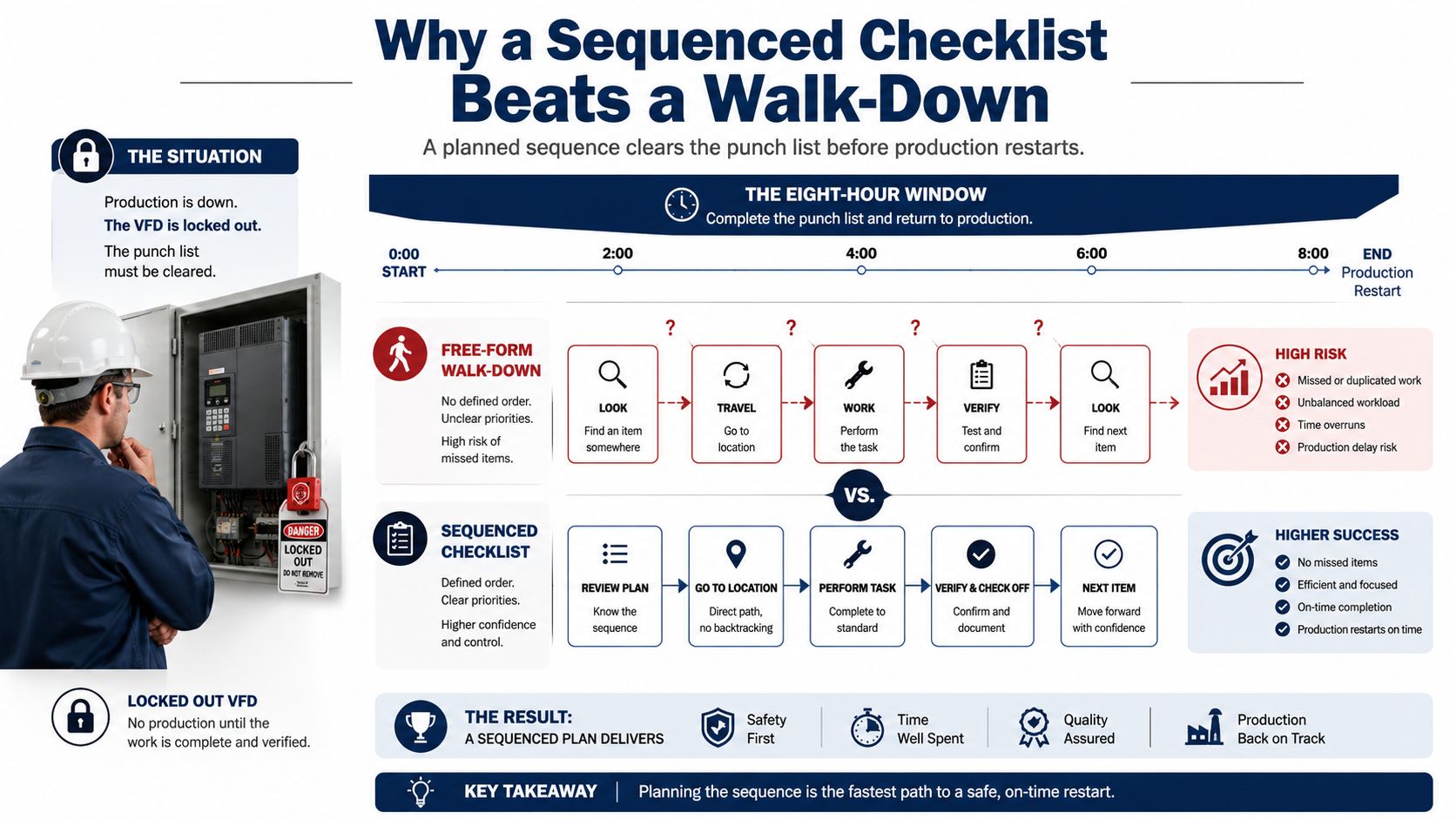
A free-form inspection makes technicians choose the next task repeatedly. That sounds harmless until several people work around the same drive cabinet. One person checks the fan while another opens the control section, then both return to the power section because nobody owns the sequence. Easy visual items receive attention, while tasks that require instruments, isolation, or a second person get pushed toward the end of the shutdown.
A sequenced checklist removes that decision burden. It moves through the cabinet in a fixed path, from isolation and incoming power to the DC bus, control terminals, cooling path, motor connections, and post-maintenance verification. The sequence matters because it reduces unnecessary movement and makes it easier for a supervisor to see what has been completed.
Start with safety and baseline conditions
The first block should identify the asset, confirm the work order, isolate the cabinet, apply lockout and tagout, and verify the absence of hazardous energy according to the site procedure. Residual energy checks belong here, not as a note buried near the bottom. The technician then records the pre-maintenance condition, including alarms, event history, cabinet temperature, fan status, and any available motor readings.
This order creates a reference point. If the cabinet runs cooler after cleaning, or if a fault returns after restart, the team has a before-and-after record rather than a vague statement that the drive was “serviced.”
Move through zones, not random components
Group tasks by physical location. Complete the power zone before moving to control terminals, then inspect the cooling path before closing the cabinet. This prevents repeated opening and closing, reduces duplicated checks, and makes handoffs clearer when electrical, instrumentation, and mechanical technicians share the work.
Practical rule: If a checklist doesn't tell the technician where to stand and what order to follow, it's still relying on memory.
The value of preventive work comes from repeatability. The preventive maintenance guidance for industrial programs describes checklists as the operating mechanism for recurring inspections, cleaning, lubrication, calibration, and documentation. That structure supports the commonly cited shift from reactive to preventive maintenance, associated with about 12% to 18% lower maintenance costs, when the routines are applied consistently.
A thorough-looking list that produces no trend data and no work orders is paperwork. A shorter sequence with asset IDs, readings, acceptance criteria, sign-off, and escalation rules is a maintenance control.
Drive Cabinet Inspection Tasks
Inspect the cabinet in three physical zones. Don't begin with the components you know best. Begin where energy enters, then follow the electrical and thermal path through the enclosure.
Power zone
With the cabinet safely isolated and discharged, inspect incoming lugs, bus connections, fuse holders, contactors, DC bus components, grounding conductors, and visible power semiconductor areas. Torque verification must follow the equipment manufacturer's specification and the site's approved procedure. A visual check won't reliably identify a termination that has lost clamping force.
Look for bus bar discoloration, heat damage around fuse holders, contactor pitting, cracked insulation, capacitor bulging or leakage, and PCB discoloration near gate-driver areas. These are useful failure signatures because they connect a physical observation to electrical or thermal stress. “Clean” isn't a failure criterion, and a cabinet can look tidy while a hot connection continues to degrade.
Control zone
Inspect terminal block tightness, wire ferrules, shield terminations, grounding continuity, ribbon cable seating, keypad condition, and HMI contrast. Check for loose conductors that can respond to vibration, damaged cable insulation, and connectors that have been disturbed during earlier troubleshooting.
Some control checks can be performed energized under an approved safe-work procedure, but exposed energized work must never be added casually to a checklist. If the task requires access inside the energized cabinet, the procedure must state the qualified personnel, boundaries, measurement method, and protective controls.
Cooling zone
Inspect heatsink dust loading, fan blades, fan bearings, thermistors, air filters, cabinet vents, and pressure or airflow paths. A fan that turns by hand may still fail under load. Listen for roughness, check for axial or radial play where appropriate, and verify operating behavior using the approved electrical measurement or drive diagnostic.
| Zone | Inspection Task | Power State | Failure Signature |
|---|---|---|---|
| Power | Inspect lugs, bus connections, fuses, contactors, and capacitors | Isolated and verified de-energized | Discoloration, pitting, loose hardware, bulging capacitor, heat damage |
| Power | Verify selected power and grounding termination torque | Isolated and verified de-energized | Torque below specification, damaged conductor, overheated connection |
| Control | Check terminals, ferrules, ribbon cables, shields, and keypad | De-energized unless an approved energized procedure applies | Loose conductor, lifted shield, unseated connector, unreadable display |
| Cooling | Clean heatsinks and inspect filters and fans | Isolated for physical work | Dust matting, blocked airflow, rough bearing, cracked blade |
| Cooling | Verify fan operation and thermistor response | Energized only under approved procedure | Fan not reaching operating condition, abnormal current, implausible temperature |
| Cabinet | Record temperature, fan current, and DC bus ripple | Measurement state defined by procedure | Rising thermal trend, abnormal ripple, worsening pre/post comparison |
Record cabinet temperature, fan current, and DC bus ripple in the maintenance log, along with ambient conditions and operating load where available. A single reading can confirm a condition. Repeated readings reveal whether the condition is changing.
Motor-Side Checks That Pair with the Drive
A drive can report an overcurrent, ground fault, or overload while the underlying problem sits in the motor, coupling, bearings, cable, or driven machine. The motor inspection therefore needs its own sequence and its own history.
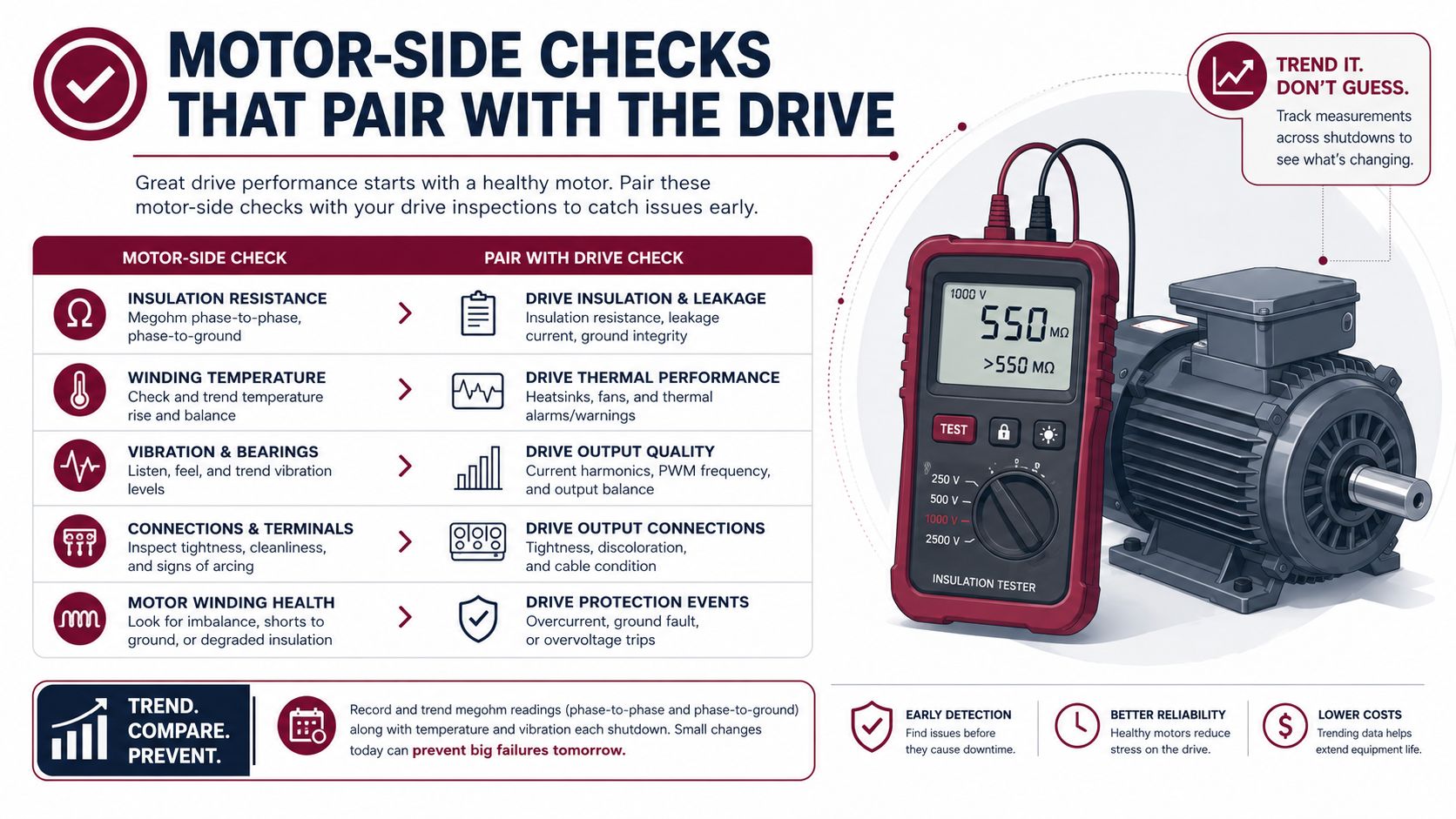
Start with the motor identification, nameplate data, insulation system, connection arrangement, bearing configuration, and installed sensors. Perform insulation resistance testing phase-to-phase and phase-to-ground only under an approved procedure, with the motor isolated from the drive and sensitive connected devices protected or disconnected as required. The acceptable result depends on the motor's voltage class, temperature, test method, and applicable manufacturer or site standard, so a generic pass/fail number shouldn't be copied into a checklist.
Trend the condition, not just the result
Record the test voltage, winding temperature, humidity or environmental condition where relevant, test duration, individual readings, and the comparison with prior results. A falling trend can matter even when the latest reading still appears serviceable.
Vibration should be captured at defined points and directions, using the same measurement method across outages. Compare the current reading and spectrum with the established baseline. Bearing grease condition, lubricant contamination, stator RTD or thermistor resistance, coupling condition, alignment, and soft-foot checks belong in the same record because a VFD trip can be the symptom of a mechanical problem.
A motor that runs quietly during a short test can still be misaligned, soft-footed, or developing a bearing fault. The useful question is whether its readings are stable against its own history.
Verify alignment between the motor and driven equipment after any work that could disturb the base, coupling, shims, or connected machine. Then compare motor current with drive output and review the VFD trend logs. A post-maintenance no-load current comparison can expose developing rotor or mechanical issues before protection trips, provided the test is performed under controlled conditions and interpreted against the motor's design data.
Use a documentation record with these fields:
- Asset identity: Motor ID, drive ID, location, manufacturer, model, and nameplate details.
- Test conditions: Load state, speed, temperature, test instrument, and technician.
- Electrical results: Insulation readings, phase balance, sensor resistance, and drive output.
- Mechanical results: Vibration points, spectrum reference, alignment status, bearing observations, and coupling condition.
- Decision record: Accept, monitor, repair, retest, or escalate, with the reason and responsible role.
The equipment condition monitoring guidance is useful when you're deciding which readings deserve continuous or periodic trending rather than one-time entry.
Use the following visual as a field reminder, not as a substitute for the approved test procedure.
The video below can support technician training around motor and drive inspection fundamentals.
<iframe width="100%" style="aspect-ratio: 16 / 9;" src="https://www.youtube.com/embed/o_o66ZMexfQ" frameborder="0" allow="autoplay; encrypted-media" allowfullscreen></iframe>Sample Frequency Schedules for Every Asset Tier
A frequency matrix should separate quick observations from tasks that require instruments, isolation, coordination, or a longer production window. Daily checks are valuable for detecting change. They shouldn't be overloaded with tasks that technicians can't perform safely or consistently during operations.
The matrix below assumes normal service. Dust, humidity, high ambient temperature, salt exposure, frequent starts and stops, and high consequence of failure should tighten the interval or move the task to a condition trigger.
| Task Category | Daily | Weekly | Monthly | Quarterly | Semi-Annual | Annual |
|---|---|---|---|---|---|---|
| Drive status | Check alarms, indicator state, noise, and abnormal smell | Review recurring alarms and operator notes | Review event history and operating trend | Compare fault patterns with prior quarter | Validate trend direction and open actions | Review failure history and revise tasks |
| Cabinet condition | Observe temperature, airflow, and visible contamination | Check enclosure exterior, vents, and door seals | Inspect filter condition and fan behavior | Perform detailed thermal and cooling review where justified | Clean internal paths during planned isolation | Complete full cabinet inspection and acceptance record |
| Power zone | Observe signs of heat or odor without opening energized sections | Review operator reports of nuisance trips | Check accessible external connections | Inspect selected terminations under approved isolation | Verify torque on selected critical connections | Complete power-section inspection and component condition review |
| Motor condition | Listen for abnormal noise and observe vibration or temperature change | Review operator readings and lubrication status | Trend current, temperature, and vibration where instruments are available | Compare condition data with baseline | Inspect bearings, alignment, and sensors as scheduled | Perform detailed electrical and mechanical assessment |
| Insulation and sensors | Not normally performed | Not normally performed | Not normally performed | Use only where criticality and procedure require | Test insulation and verify RTD or thermistor condition | Perform planned insulation and sensor verification |
| Records | Log abnormal observations | Close or assign findings | Review overdue actions | Audit completion and quality of readings | Update spares and work scope | Approve the next frequency matrix |
The VFD maintenance schedule guidance can help align calendar tasks with operating conditions and shutdown planning. The schedule should remain a controlled document, with revision history, asset ID, completion date, technician sign-off, readings, findings, and linked work orders.
If the site can't complete a full annual scope, compress the work without deleting the high-value measurements. Keep safety isolation, termination condition, cooling performance, insulation trend, motor condition, and pre-energization checks. Defer cosmetic cleaning or low-consequence observations only after the responsible supervisor records the decision and risk owner.
A practical program also measures adherence. Commonly cited benchmarks include PM compliance above 90%, a planned-to-unplanned maintenance ratio near 80/20, and maintenance cost at 2% to 5% of asset replacement value, as summarized in preventive maintenance program guidance. Treat these as management reference points, not automatic proof that a checklist is effective.
Risk-Based Priorities for Critical Drive Systems
Not every VFD deserves the same inspection depth. A spare conveyor drive in a non-bottleneck area may tolerate a fixed schedule and basic trend checks. A single induced-draft fan, cooling pump, or process blower may justify deeper monitoring because its failure affects production, safety, environmental control, or restart time.
Score each asset against four practical questions:
- Failure consequence: What happens if the drive or motor trips? Consider production loss, safety exposure, environmental impact, and product damage.
- Redundancy: Can another asset carry the load, or is this the only available path?
- Repair time: Can the crew diagnose and restore it during the available window?
- Spare lead time: Is a compatible power module, control board, fan assembly, or complete exchange unit immediately available?
You don't need a complicated model. Use a consistent low, medium, and high assessment for each factor, then assign the asset to a tier after a cross-functional review. The important part is repeatability and ownership. Maintenance, operations, electrical engineering, and procurement should agree on the consequence and the response.
How the tiers change the checklist
Tier 1 critical assets receive condition-based triggers, deeper trend review, thermal inspection at a defined recurring interval, and on-condition replacement of parts that show deterioration. Sensor data can support the program, but only if someone owns data quality, alarm limits, and response actions. Predictive methods are not a cure for missing asset records or inconsistent measurements.
Tier 2 assets combine fixed schedules with selected measurements. The crew may trend vibration, temperature, current, and fault history during planned inspections, then increase inspection depth after a warning sign.
Tier 3 assets generally remain on fixed intervals with minimal instrumentation. The checklist should still cover safety, cooling, visible damage, and basic operating condition, but it doesn't need the same monitoring burden as a single-point process drive.
Consider two VFDs with similar physical construction. A feed conveyor drive with available bypass capacity, accessible spares, and limited process consequence may sit in Tier 3. A boiler induced-draft fan drive with no practical redundancy, long restart implications, and safety or environmental consequences belongs in Tier 1. The cabinet tasks overlap, but the Tier 1 drive receives deeper trending, more deliberate spare planning, and condition triggers instead of relying only on calendar dates.
Review the tier after every significant incident, repeat fault, process change, or spare-parts decision. A drive that was ordinary before a production expansion can become a single point of failure afterward.
Checklist Items Most Teams Skip
The skipped tasks are rarely the glamorous ones. They're the checks that require a torque tool, a baseline, a second person, or a decision that may create follow-up work.
Termination torque
Technicians often inspect power and ground terminations visually and move on. That misses connections that look normal but have lost clamping force. Thermal damage around a lug may be the final visible stage of a problem that torque verification could have identified earlier.
Use the manufacturer's torque requirement, the correct tool, and a documented sampling plan. Don't mark “tight” as a result. Record the termination or group checked, the tool status, the observed condition, and any corrective action.
Baseline readings
A commissioning record gives later technicians something to compare. Capture insulation resistance, vibration readings or spectra, thermal images where justified, motor current, cabinet temperature, fan behavior, and relevant drive parameters when the asset is known to be healthy.
Without that baseline, “higher than normal” has no clear meaning. The crew ends up debating whether a reading is acceptable instead of deciding whether the asset is deteriorating.
Record the reference, not just the result. A measurement without its conditions is difficult to use during the next outage.
Pre and post comparison
Cleaning a heatsink, replacing a filter, or changing a fan should produce a documented comparison. Record the same measurement before and after the work, under comparable conditions where possible. If temperature or fan current doesn't improve, the job isn't complete just because the part was replaced.
Other commonly missed items include:
- Spare-drive condition: Check storage conditions, visible capacitor deterioration, packaging damage, and service history before the exchange unit is needed.
- Outdoor enclosure sealing: Inspect gaskets, gland plates, drain paths, and door closure. A cabinet can be clean inside today and still be admitting moisture.
- Fan performance under load: Verify that the cooling fans rotate at the expected operating condition, not merely that they turn during a brief visual check.
- Parameter backup: Confirm that the active parameter set is saved, identified, and matched to the correct motor and application.
- Repeat-fault linkage: Connect the current finding to earlier alarms, work orders, and replaced parts. A new fan won't solve a recurring trip if airflow restriction or control instability remains.
These entries make the checklist diagnostic. They turn maintenance from a collection of completed boxes into evidence that supports the next decision.
Your Shutdown-Week Action Plan
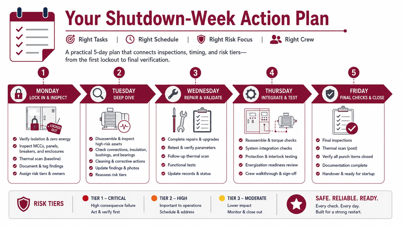
A shutdown plan works when each day has a defined output. Don't assign a large undifferentiated list to the crew and hope the last afternoon absorbs the unfinished work.
Monday starts with control and isolation
Confirm the asset list, permits, drawings, procedures, spares, instruments, and accountable roles. Lock out the cabinet, verify isolation and residual energy status, record baseline conditions, and complete the power-zone inspection. Any finding that threatens safe access or restart becomes a hold point.
Tuesday covers control integrity
Inspect terminal blocks, ferrules, shields, ribbon cables, parameter storage, keypad or HMI condition, and communication connections. Record discrepancies against the approved drawings and create a work order for anything that can't be corrected inside the window.
Wednesday follows the heat path
Clean approved cooling paths, inspect heatsinks and filters, evaluate fans, verify thermistors, and compare thermal or temperature records with the baseline. Motor-side technicians can perform alignment checks, vibration collection, sensor verification, and approved insulation testing in parallel during the available pre-start windows.
Thursday is the gate before energy returns
Complete the re-test and verification stage:
- Electrical gate: Confirm insulation results, motor connections, grounding, and selected torque checks.
- Configuration gate: Verify parameter backup, motor data, control mode, interlocks, and stored fault history.
- Mechanical gate: Confirm coupling guards, alignment status, lubrication actions, and free movement.
- Cooling gate: Confirm filters, fans, airflow paths, enclosure closure, and sensor response.
- Documentation gate: Ensure every exception has an owner, priority, and restart decision.
No restart should proceed with an unresolved stop-hold condition unless the authorized plant role accepts the documented risk under the site process.
Friday closes the record
Run the controlled restart, capture post-maintenance readings, review alarms, and compare drive and motor behavior with the pre-work record. Close the punch list only when evidence supports the result. Tier 1 findings that couldn't be corrected should become planned follow-up work orders with parts, access requirements, and a responsible owner.
Print a shutdown-day card with these fields:
- Stop hold: Unsafe isolation, abnormal insulation result, exposed damage, failed cooling, unresolved parameter mismatch, or unacceptable post-start behavior.
- Accountable role: Electrical supervisor for isolation and termination decisions, reliability engineer for condition trends, operations lead for restart authorization, and maintenance planner for follow-up work orders.
- Required evidence: Before and after readings, photographs where permitted, torque records, test instrument identification, parameter backup confirmation, and signed acceptance.
- Escalation path: Named contact for engineering, operations, procurement, and specialist support.
A field service partner can support the work when the site lacks the time, instruments, or drive-specific diagnostic capacity. DUCHENG Industrial provides multi-brand VFD commissioning, shutdown preventive care, troubleshooting, workshop repair, on-site reconditioning for medium- and high-voltage drives, spare-parts compatibility review, and documented recommissioning support for industrial facilities.
If your next shutdown includes VFDs, motors, or drive cabinets, use this sequence to build the work pack before the outage starts, then invite DUCHENG Industrial to support condition checks, fault diagnosis, preventive care, or controlled recommissioning. Share the asset list, operating constraints, and planned window so the service scope can focus first on the drives carrying the greatest production and safety risk.