
Infrared Thermography Electrical inspections done safely: load rules, temperature difference bands, hot-spot diagnosis and reporting.
If a connection looks hotter than the one beside it, have you found a loose joint, or just a different load, surface finish, or reflection? That distinction determines whether an infrared thermography electrical inspection produces a useful work order or an unnecessary repair.
A thermal image is a lead, not a verdict. For drives and switchgear, a defensible finding combines a repeatable image, a recorded operating condition, a valid reference, and electrical checks. The camera helps you decide where to investigate. It doesn't authorize opening a live cabinet, tightening a terminal, or restarting a tripped drive.
Table of Contents
- How to Prepare a Thermal Survey That Holds Up
- How to Scan Energized Equipment Step by Step
- Turn a Hot Spot Into a Temperature Difference Decision
- Failure Signatures in Drives and Switchgear
- Writing a Thermal Report That Drives Action
- Choose a Thermal Survey Program for Your Assets
How to Prepare a Thermal Survey That Holds Up
Prepare the route before the camera leaves the bag. A survey without an access plan and representative loading can produce attractive images that nobody can confidently compare or act on.
Build the route and operating baseline
- Review the documents. Check the single-line diagram, nameplate ratings, maintenance history, fault records, and previous thermal images. These tell you which components are comparable and which changes deserve attention.
- Define the inspection targets. List the drives, panels, and switchgear in scope, including accessible terminations, bus joints, fuses, contactors, reactors, braking resistors, DC-link assemblies, and cooling paths. Identify concealed targets as access limitations, not inspected components.
- Arrange the load window. Ask operations when each circuit carries its representative production load and whether it will remain stable long enough to reach operating temperature. A scan during an idle interval won't represent a heavily loaded production run.
- Choose suitable weather. Avoid direct solar heating, strong wind, and rain where practicable. Otherwise, you may be comparing environmental heating or cooling rather than electrical condition.
Check the measurement and safety arrangements
Confirm that the camera can resolve the actual connection from the permitted working position. Focus on the measurement target, not the cabinet outline.
Identify each target's surface condition and establish an appropriate emissivity setting rather than assigning one setting to every material. Record reflected-temperature and infrared-window compensation where applicable. Window transmission and target emissivity are separate inputs.
Confirm qualified-person responsibilities, energized-work authorization, arc-flash boundaries, and PPE before scheduling access. Identify suitable infrared windows and verify their field of view. An inspection point that cannot safely reveal the intended component needs a different access strategy.
Preparation rule: Put inaccessible targets on the exception list. Never turn an incomplete view into a clean bill of health.
Copyable preparation sheet
| Field | Record before or during the survey |
|---|---|
| Identification | Site, asset ID, circuit, date, inspector |
| Operating condition | Expected load, measured current, operating mode, stabilization status |
| Environment | Ambient temperature, weather, nearby heat sources |
| Camera setup | Camera and lens, emissivity, reflected-temperature setting, focus, distance |
| Optical path | Window ID and transmission compensation, viewing angle |
| Comparison | Reference component and measurement location |
| Safety and access | Authorization, qualified personnel, boundaries, PPE, excluded targets |
How to Scan Energized Equipment Step by Step
The survey walk should produce comparable observations without expanding the worker's exposure. Technical guidance doesn't replace equipment documentation or on-site safety procedures. Follow the drive or switchgear manual and the site's approved electrical-safety process.
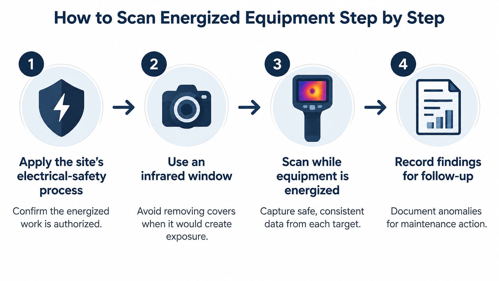
The process graphic summarizes the safe inspection sequence.
-
Authorize the task and establish the safe viewing position. Confirm who may access the equipment, what energized inspection is authorized, and which protective measures apply. Use a suitable infrared window where cover removal would create unacceptable exposure; a camera doesn't make exposed energized parts safe.
-
Confirm representative loading. Inspect at normal operating load whenever practicable. The NFPA 70B committee document permits a single-point inspection at no less than 40% of nominal circuit loading when normal loading isn't feasible, provided the equipment has operated long enough to reach steady-state temperature. Treat this as a conditional inspection option, not proof that a lightly loaded scan represents maximum production duty.
-
Capture the operating condition with the image. Record load current, ambient temperature, operating mode, scan distance, camera settings, and the selected reference component. If operations changes speed, torque demand, or process duty during the route, mark the affected images so they aren't treated as steady-load comparisons.
-
Scan the assembly before measuring individual points. Look at the overall distribution of heat, then inspect accessible connections and components. A broad warm area suggests a different investigation from concentrated heating at a joint, so don't begin by selecting only the brightest pixel.
-
Compare phases and parallel components consistently. Use comparable distances, viewing angles, surface finishes, and operating loads. Move to another safe angle when a suspected reflection appears; if the bright feature shifts with the camera, investigate the optical effect before classifying the equipment.
-
Calculate and label the temperature differences. Record both the anomaly-to-reference difference and the anomaly-to-ambient difference. Keep them separate: a comparison against another phase isn't interchangeable with a comparison against surrounding air.
-
Collect the drive-specific evidence. Note phase-current imbalance, available harmonic measurements, torque or load changes, fan operation, filter condition, and fault history. Use instrumentation suitable for the measurement location and drive waveform; don't treat an unsuitable output-current reading as confirmation of an internal drive fault.
-
Save evidence that another technician can locate. Pair the thermal image with a visible-light photograph and matching asset labels. Identify the precise joint or component, the reference point, and any obstruction so the repair crew doesn't have to guess what the thermographer measured.
Mistakes that invalidate an otherwise useful scan
- Low or changing load: Record the limitation and arrange a representative rescan rather than assigning false confidence.
- Unsuitable covers: Visible transparency doesn't establish infrared transparency. Don't measure through an unknown barrier.
- Poor focus or excessive distance: A target can be visible without occupying enough of the measurement area for a dependable reading.
- Shiny-metal reflections: Check a second safe viewing angle and an appropriate reference surface.
- Incorrect emissivity: Match the actual surface condition and document uncertainty when quantitative measurement isn't defensible.
Don't reach into energized equipment to add tape, alter a target, or improve the view. Plan any approved reference-target installation for a safely isolated condition.
The scan records conditions at that moment. After corrective work, schedule a follow-up under comparable operating conditions and verify that the original pattern has changed.
Turn a Hot Spot Into a Temperature Difference Decision
Is this hot spot a real problem? Calling it a loose connection immediately is the common overcall. Emissivity, reflected radiation, viewing angle, airflow, load, enclosure geometry, and camera uncertainty can all change the apparent reading.
NFPA 70B committee materials describe thermography of energized connections and terminations and inspection intervals ranging from 6 to 12 months, depending on equipment condition. Those provisions don't make a thermal pattern an automatic repair instruction.
Establish a valid comparison before assigning severity
Check the load first. Then compare like components with like surfaces, account for phase-current differences, and record the ambient condition. If the process has just changed duty, wait for stabilization and repeat the measurement.
ΔT means target temperature minus the stated reference temperature. Always identify that reference. Don't mathematically adjust a reading to another load unless the site's approved method supports that calculation.
Temperature difference bands and actions
Numerical severity bands must come from the site's adopted procedure and applicable equipment guidance. The following decision table deliberately uses procedure-defined bands rather than presenting unsupported universal temperature cutoffs.
| Temperature difference (ΔT) | Classification | Action | Re-scan |
|---|---|---|---|
| Within the site's baseline band at normal load | No detected thermal anomaly | Store as baseline image; record measurement limitations | Routine interval |
| Within the site's possible-deficiency band | Possible deficiency | Investigate comparability, log the finding, and trend it | Next scheduled survey, or sooner if evidence warrants |
| Within the site's intermediate band | Intermediate | Plan isolated connection checks and cause-specific correction | After correction |
| Above the site's serious-anomaly threshold | Serious | Escalate promptly; assess controlled shutdown against condition and consequence | After repair and safe restoration |
| Any hot spot below the applicable inspection-load criterion | Inconclusive severity | Retain the evidence, assess immediate hazards, and avoid a definitive thermal classification | After acceptable load and stabilization |
An inconclusive classification doesn't mean permission to keep running. Burning smells, damaged insulation, abnormal noise, protection events, or deteriorating trends require escalation through the site's response procedure regardless of the thermal category.
No hot spot doesn't mean healthy. It means the inspection didn't reveal a thermal exception within its viewing and operating limits.
Intermittent faults, capacitor degradation, concealed restrictions, and problems that emerge only at another duty point can escape detection. Pair the image with alarm logs, operating history, contamination evidence, and electrical measurements.
Select the next test by the suspected mechanism. A joint may need isolated torque and contact checks; phase-wide heating may require current and harmonic analysis. Insulation testing or capacitor assessment needs an equipment-specific test plan, including isolation from sensitive electronics where required. Never rank findings by apparent temperature alone.
Failure Signatures in Drives and Switchgear
A single lug hotter than its comparable phase partner is a useful starting point, not proof that it needs tightening. The connection may be loose, oxidized, damaged, or carrying a different current. Verify those possibilities before replacing hardware or disturbing the joint.
Hot-spot patterns, likely causes and first actions
All hands-on connection work in this table assumes approved isolation, verification of electrical status, and control of stored energy.
| Hot-spot pattern | Likely cause | Verify with | First action |
|---|---|---|---|
| Single lug or bus joint hotter than its phase partner | Loose or oxidized termination | Manufacturer-approved torque verification and contact-resistance checks | Inspect the joint; restore to specification or replace damaged parts, then rescan |
| One phase hotter across drive input and output | Phase imbalance or overload | Suitable phase-current measurements and load history | Check loading and investigate input and output separately before replacing parts |
| Heatsink or cooling path warm, fan area hot | Blocked filter or failed fan | Fan operation, filter condition, and fault log | Clean the path or replace the defective fan or filter |
| Hot DC-link or capacitor assembly under sustained load | Capacitor aging or thermal stress | Fault history, suitable harmonic measurements, and manufacturer-approved capacitor assessment | Plan controlled testing and replacement if degradation is confirmed |
| Hot fuse or contactor at steady current | Rating mismatch or poor contact | Measured current, component rating, and comparable component | Investigate the rating and contact path; schedule justified replacement |
| Bright reflection on shiny metal | Reflected radiation or low emissivity | Another safe viewing angle and a suitable reference surface | Exclude the apparent reading from severity classification until confirmed |
Verify the mechanism, not just the pattern
For a lug or bus joint, inspect for discoloration, damaged strands, corrosion, and evidence of overheating after isolation. Torque alone isn't a condition test: damaged contact faces won't become serviceable merely because a fastener reaches its specified torque.
For phase-wide heating, compare current readings with the process load history. A drive's input and output aren't thermally equivalent circuits, so avoid assuming that a hot input phase and a hot output phase share a direct cause.
For a cooling problem, confirm actual airflow and fan operation rather than relying only on a run command. Check the event log for temperature-related trips and inspect obstructions along the complete cooling route.
For a DC-link assembly, use the thermal pattern to target further assessment. Harmonic readings and fault history provide context, but neither alone proves capacitor health or failure.
For fuses and contactors, establish whether heat is concentrated at a connection or distributed through the component. Use the same asset identification and connection documentation discipline applied in motor control center maintenance.
For a reflection, retain the images showing the changed viewing angle. That documents why the apparent hot spot wasn't treated as component heating.
When a drive trips, our diagnosis combines fault codes and event logs with visual and thermal inspection, electrical-safety checks, parameter and signal-path review, and component-level troubleshooting. Controlled restart and functional verification follow only when the safety conditions are met. The thermal image remains one input among several.
Writing a Thermal Report That Drives Action
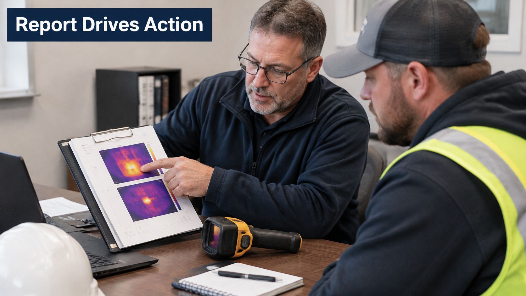
A useful report lets the work planner assign a clear next step without asking the inspector to identify the target. Separate what the scan shows from what still needs confirmation.
For each finding, state the asset and exact location, the observed pattern, the measured temperature difference, and the classification basis. Use measured values and label the thermal and visible-light images. State confidence limits plainly, such as a restricted view or uncertain surface emissivity. Classify the finding as an observation, a suspected issue requiring checks, or a confirmed defect only when supporting electrical evidence justifies that conclusion.
Discuss the findings with the person who will authorize and schedule the work.
Make the comparison reproducible
For a repeat finding, report whether the comparison is valid and why. A change in temperature can reflect a change in duty rather than deterioration. If conditions differ, label the trend inconclusive instead of implying improvement or worsening.
The historical account in IRINFO's review of NFPA 70B notes that the 2002 edition added circuit-loading characteristics to infrared reporting requirements. That reporting discipline matters for drive assets, where process duty can vary between inspections.
Use wording that distinguishes the observation from the required verification:
Report wording: The identified phase lug showed an elevated temperature relative to the recorded comparison lug under stable production duty. Verify the connection during approved isolation. Correct any confirmed defect to the manufacturer's requirements, then repeat the scan under comparable conditions.
A trend entry should identify the prior finding, current status, work completed, and whether operating conditions allow a valid comparison. Include the assigned follow-up date and the condition needed for verification. The report should rank work by failure consequence, supporting electrical evidence, deterioration, and available redundancy. A smaller confirmed anomaly on a critical feeder may take priority over a hotter surface that is normal for its function.
Use the video as a discussion aid alongside the documented findings.
<iframe width="100%" style="aspect-ratio: 16 / 9;" src="https://www.youtube.com/embed/gCKtltw-v0s" frameborder="0" allow="autoplay; encrypted-media" allowfullscreen></iframe>Close the work order with an owner, a specific verification task, and a follow-up date. A thermal image is a lead, not a verdict: require load context and electrical checks before deciding on repair.
Choose a Thermal Survey Program for Your Assets
What should a thermal survey program cover: broad periodic checks, continuous monitoring, or both? Choose based on the assets' failure consequences, access constraints, and the response the site can support. Continuous data helps only when sensors monitor useful locations and someone is responsible for acting on alerts.
Handheld surveys, permanent sensors and analytics compared
| Method | Best use | Strength | Limitation |
|---|---|---|---|
| Handheld survey | Broad periodic coverage and commissioning | Examines accessible targets across a cabinet or lineup | Snapshot only; depends on a trained operator and line of sight |
| Permanent sensors | High-consequence drives and hard-to-access points | Continuous alarms, trend data, and fewer energized exposures | Watches selected points only; may drift |
| Edge or AI analytics | Large fleets with a reliable baseline | Automated flagging of anomalies | Accuracy from other sites may not transfer; needs alarm rules |
Begin with a handheld baseline across the asset group. Record accessible targets and blind spots, then identify which locations warrant permanent monitoring.
Fixed sensors can help where failure consequences are high or routine access is difficult. They complement diagnostic coverage; they do not automatically provide a cabinet-wide inspection. A sensor at a bus joint, for example, may not detect a blocked filter elsewhere in the enclosure.
Confirm that a proposed sensor arrangement meets the site's adopted requirements and suits the installation. A sensor at one point cannot establish the condition of every connection or component in a cabinet.
Establish alarm governance before automation
Set the baseline, alarm thresholds, calibration responsibilities, and escalation process before adding automated image analysis. Assign responsibility for records and settings, define how communications are secured, and decide what happens when a sensor stops reporting.
A thermal alert should prompt a controlled assessment, not an automatic restart or replacement decision. Have an engineer consider the operating state, protection history, and corroborating measurements before deciding what action is appropriate.
Where the site lacks trained thermographers or needs shutdown support, include inspection in electrical preventive maintenance. DUCHENG Industrial's Preventive Care includes operating-condition review, visual and thermal imaging inspection, safe isolation and residual-energy checks, cleaning, fan and filter inspection, connection and torque checks, component recommendations, and controlled restart.
For a service assessment, send:
- Equipment details: Drive brand, model, and fault code.
- Identification photograph: A straight-on, readable nameplate image.
- Fault evidence: The display before any reset.
- Installation context: A wider photograph showing the cabinet and surrounding arrangement.
An engineer reviews each request and assesses whether an on-site or workshop path suits the equipment and situation. Choose one asset group, agree on a representative production window with operations, and assign an owner to complete its baseline survey and follow-up actions.
DUCHENG Industrial provides VFD condition inspection, preventive maintenance, and structured fault diagnosis that combine thermal evidence with electrical checks and controlled recovery. Submit drive details and installation photographs to DUCHENG Industrial for an engineer-reviewed assessment of the appropriate inspection or maintenance scope.