
Motor control center maintenance done right — inspection checklists, thermal scans, cleaning routines, component testing, and VFD interface checks explained.
A routine walk-down in a steel mill can uncover a problem that a shutdown inspection never will. An infrared scan may find a feeder termination running dangerously hot under load, while the same connection looks clean and mechanically sound after the equipment is de-energized. That's why effective motor control center maintenance can't rely on one annual checklist or one inspection method.
The reliable approach uses two coordinated tracks. The first covers de-energized mechanical work, cleaning, torque verification, and component testing under a controlled lockout. The second uses live thermal and electrical diagnostics to identify faults that only appear when motors, feeders, and drives are carrying representative load. The two tracks must share the same asset records, findings, and corrective-action process.
Table of Contents
- Why Motor Control Center Maintenance Demands a Dual-Track Approach
- Prerequisites and Safety Setup Before You Open a Bucket
- Visual and Mechanical Inspection Walkthrough
- Cleaning and Contamination Control
- Thermal and Electrical Testing Routines
- MCC and VFD Interface Checks
- Adapting the Program for Harsh and High-Duty Environments
Why Motor Control Center Maintenance Demands a Dual-Track Approach
A hot connection doesn't always leave an obvious visual clue. A loose lug, overloaded phase, deteriorated stab, or poor termination can look acceptable during an outage and still produce a serious thermal imbalance when production resumes. Live thermography supplies the missing operating context.
The reason this matters is supported by historical MCC failure data. In a compiled set of 1,097 MCC failure reports, 60 cases, or 5%, were classified as maintenance-induced, while the analysis also concluded that maintenance-induced events represented 15% of the failures reported in the dataset overall. The figures come from the historical MCC failure analysis, and they point to two separate risks. Equipment can deteriorate through heat, age, and contamination, but technicians can also introduce defects through poor torque control, misplaced hardware, damaged insulation, or incomplete verification.
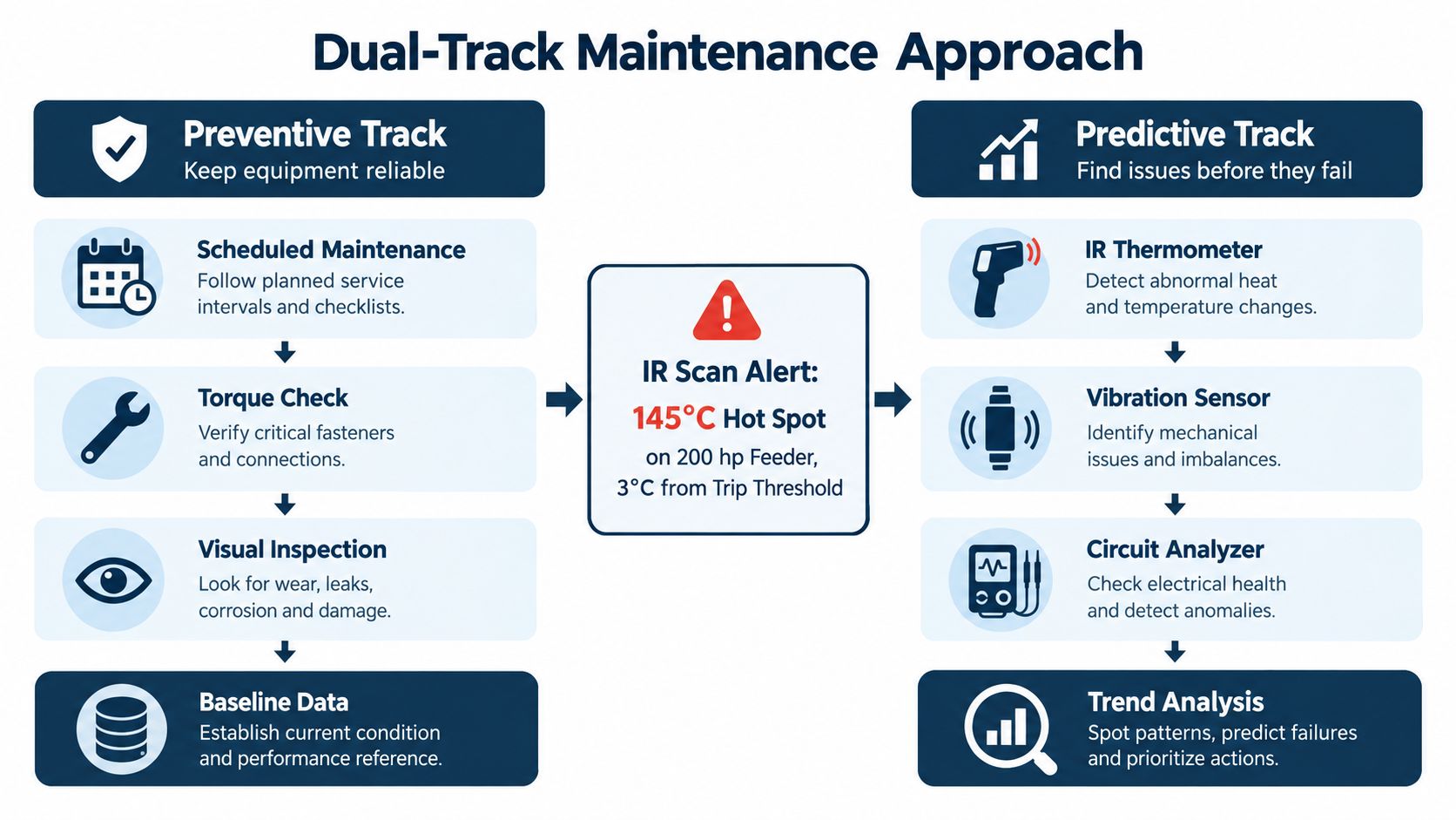
Track one covers controlled offline work
De-energized maintenance is where crews clean compartments, inspect bus structures, torque accessible connections, verify bucket mechanics, test protective components, and correct defects. This work requires a documented energy-control process, voltage verification, and a clear boundary between the equipment being serviced and adjacent energized sections.
The offline track is also where workmanship has to be controlled. Use calibrated tools, record actual torque values where required, apply torque seals when appropriate, and perform a second-person verification on critical terminations. A bucket that's been serviced but not properly seated can create a more dangerous condition than the defect found during inspection.
Track two captures operating faults
Live inspection adds information that an outage can't provide. Thermography should be performed with doors closed where the equipment design allows it, under representative load, and through properly rated viewing ports when available. The survey should compare phases on the same circuit and current conditions with prior scans, not just rely on a single color image.
NFPA 70B-aligned guidance treats MCCs as equipment requiring at least annual inspection. For thermographic inspection, the guidance supports intervals of at least every 12 months in normal condition and as often as every 6 months when physical condition is poorer, as described in this NFPA 70B guidance. Harsh plants may need tighter intervals, especially where loading changes rapidly or contamination is persistent.
For plants building a formal program, industrial electrical maintenance services can help integrate shutdown work with live diagnostic windows. The important point is sequencing. Offline work eliminates hazards and corrects physical defects. Live testing proves whether the system behaves properly under actual operating stress.
Prerequisites and Safety Setup Before You Open a Bucket
MCC work starts before anyone touches a door handle. The job package should identify the exact lineup, bucket, feeder, and upstream source, then connect those assets to the current electrical drawings and safety analysis.
Confirm the electrical boundary
Start with the latest single-line diagram, MCC elevation drawing, and device coordination study. Confirm which bucket supplies which motor and where the bus sections, tie devices, incoming sources, and backfeeds are located. A drawing that doesn't match the installed lineup is a hazard, not a reference.
The arc-flash boundary and PPE selection must match the specific section's incident-energy information. A generic PPE category won't account for differences between an incoming section, a vertical bus compartment, and an individual bucket. If labels are missing, damaged, or inconsistent with the current system configuration, stop and resolve that discrepancy through the site's electrical safety process.
Apply and verify lockout
The lockout sequence must address more than line voltage. Confirm control power, auxiliary sources, remote-start circuits, stored energy in variable frequency drive capacitors, and pneumatic or hydraulic actuators associated with particular bucket assemblies. Test for absence of voltage with an adequately rated instrument, verify the instrument before and after the test, and account for phase-to-phase and phase-to-ground conditions.
Safety rule: A locked handle doesn't prove a dead circuit. The verification step proves the condition.
Bring the right kit
A practical MCC maintenance setup includes:
- Calibrated torque wrench: Use the manufacturer's specified values and record exceptions.
- Insulation tester: Select the test voltage and method from the equipment and plant procedure.
- Contact-resistance instrument: Use it on breakers, contactors, and other applicable current paths.
- Thermal camera suitable for the access method: Confirm that windows and ports don't distort the inspection.
- Torque seals and inspection tags: Mark completed critical checks without obscuring identification.
- Documented job hazard analysis: Include adjacent energized equipment, dropped-object risks, access limits, and restart hazards.
Have the latest schematic revisions and the previous inspection's open corrective-action list at the work area. If the crew can't see what was previously found, recurring defects get treated as new discoveries and unresolved risks remain buried.
Visual and Mechanical Inspection Walkthrough
A good inspection moves in a fixed direction. Start outside the enclosure, move to the MCC structure, and finish at individual units. That order keeps technicians from opening buckets before they've identified enclosure, access, or environmental problems that could change the work scope.
Pass one checks the enclosure
Look for damaged doors, degraded gaskets, loose hinges, failed latches, blocked ventilation paths, and cracked viewing windows. Check that infrared windows and covers are intact, clean, and correctly identified. Nameplates should remain legible because accurate identification becomes critical during switching, isolation, and fault tracing.
Photograph enclosure damage, missing labels, contamination at vents, and any evidence of water or oil entry. A door that won't close squarely, a missing barrier, or a damaged IR port should send the section to corrective repair rather than back into normal service.
Pass two checks the structure
Inspect bus bracing, splice plates, incoming line connections, the ground bus, and the vertical bus stab interface. Look for discoloration, tracking, corrosion, heat damage, loose hardware, cracked insulation, and evidence that a bucket hasn't engaged evenly.
Ground bus continuity must be verified through the approved test method, not assumed from visual contact. Pay particular attention to transitions between sections and to areas affected by vibration or repeated bucket withdrawal.
Pass three checks each unit
At the unit level, inspect contactor contacts for pitting and abnormal wear. Confirm that heater elements match the motor nameplate and that overload settings reflect the approved protection design. Examine wire insulation where conductors bend, pass through barriers, or terminate at lugs.
Withdrawable buckets should move smoothly and engage their racking interlocks correctly. A unit that binds, fails to reach its intended position, or shows damaged stabs needs a controlled corrective action before energization.
| Pass | Scope | Key Items Checked | Tag-Out Trigger |
|---|---|---|---|
| Exterior | Enclosure and access | Doors, gaskets, latches, windows, IR ports, labels | Damaged barrier, failed latch, water entry, unsafe access |
| Structure | Bus and grounding | Bracing, splice plates, ground bus, incoming connections, vertical bus stabs | Tracking, corrosion, heat damage, loose or misaligned hardware |
| Per-unit | Bucket and components | Contactors, heaters, overloads, insulation, racking interlocks | Failed interlock, damaged insulation, abnormal contact wear, poor engagement |
The inspection record should identify the exact compartment, attach photographs, and state whether the finding is acceptable, monitor-only, or a repair prerequisite. “Checked” isn't enough. The next technician needs to know what was seen and why the unit was released.
Cleaning and Contamination Control
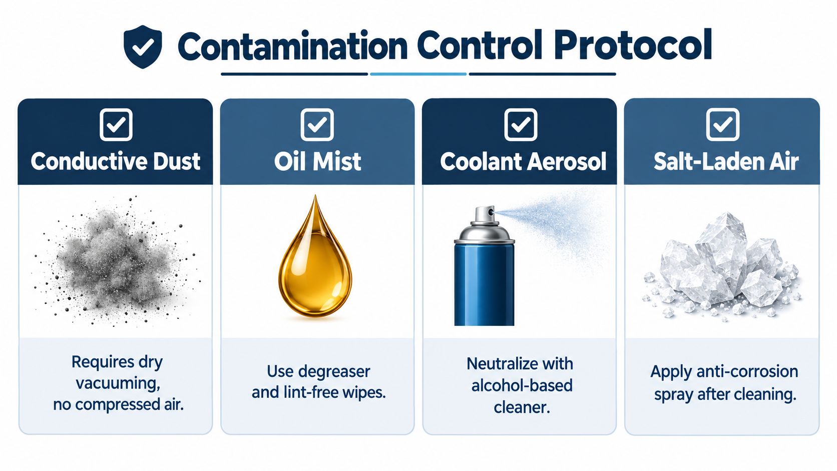
Cleaning controls contamination. It is not cosmetic work. The contaminant points to the likely failure mechanism. Conductive dust can form tracking paths across insulation. Oil mist can soften or coat insulating surfaces and collect more debris. Coolant aerosol leaves moisture-holding residue, while salt-laden air accelerates corrosion on copper, plated hardware, and terminations.
Match the method to the contaminant
Use dry vacuuming for loose conductive dust, with equipment and procedures suited to the de-energized condition. Use lint-free wipes on accessible surfaces. For localized resin or residue, apply a compatible alcohol-based cleaner. Keep brushes grounded and approved for the task. Improvised tools can shed fibers or create static concerns.
Never blow shop air across live equipment. Do not use water-based degreasers inside MCC compartments or connect a shop vacuum to an energized bus. Compressed air can drive conductive particles into pockets, barriers, and contact surfaces instead of removing them.
Clean from the top down
After lockout and absence-of-voltage verification, remove only the bus shrouds and barriers permitted by the maintenance procedure. Vacuum from the top down so loosened material does not settle on surfaces already cleaned. Use narrow attachments around bus pockets, breaker compartments, bucket interfaces, and ventilation paths.
Then wipe the areas that collect deposits. Pay particular attention to horizontal surfaces, insulation interfaces, termination points, and cooling openings. A harsh-environment plant may need a different cleaning interval from a clean indoor facility. Steel dust, tire-building residue, chemical vapors, and coastal salt each demand inspection scope based on the actual contaminant.
Contamination that has penetrated insulation, caused tracking, or produced corrosion cannot be cleared by wiping alone. The affected component may require replacement or specialist assessment before release.
Fix the source or repeat the work
A leaking roof, unfiltered intake, oil-mist source, open cable entry, or poorly arranged ventilation path will undo a careful cleaning job. Where the facility design supports it, consider enclosure sealing improvements, filtered ventilation, drip shields, and positive-pressure electrical rooms.
Record the contaminant, location, severity, and suspected entry path. Include the MCC to VFD boundary when residue, dust, or blocked cooling paths could affect both sections. That record lets the next planner adjust inspection scope and interval from observed conditions instead of repeating the same calendar task without learning from the findings.
Thermal and Electrical Testing Routines
Thermal and electrical tests answer different questions, so schedule them as one coordinated work package. Infrared inspection shows how connections behave under actual load. Insulation and contact-resistance tests show electrical condition while equipment is isolated. One routine can miss a defect that the other exposes.
Start with a representative thermal survey
Perform a live infrared survey under representative loading, and document the enclosure configuration. Compare phase-to-phase temperatures, similar circuits, and earlier readings from the same equipment. Record load condition, ambient conditions, measurement location, relevant emissivity assumptions, and the measured temperature difference.
Absolute temperature can mislead when equipment is lightly loaded or compartment airflow varies. A developing phase imbalance or a repeated hot spot at the same termination usually provides more useful evidence than one isolated image. In steel, tire, chemical, and coastal plants, contamination and changing ventilation can shift the thermal pattern, so record those conditions with the image.
Treat the annual baseline from your plant's NFPA 70B program as a floor, not an answer for every plant. Harsh environments, high-duty motors, and critical process feeders may justify more frequent surveys. Set that interval from loading, contamination, failure history, and the consequence of losing the feeder.
Use offline tests to explain the image
During the de-energized window, perform insulation-resistance testing on bus and control wiring where the equipment procedure permits it. Apply polarization-index testing where appropriate, and compare results with equipment history rather than relying on one generic pass value. A declining trend deserves investigation even when the latest reading appears acceptable.
Check breaker and contactor resistance with a suitable low-resistance instrument. High or uneven resistance can support a thermal finding, but a normal result does not clear a load-related hot spot elsewhere in the circuit. Review protective-device settings, coordination documentation, and ground-fault functions where installed, especially after system changes or unexplained trips.
| Test Type | Clean / Indoor | Dust / Oil Mist | Chemical / Coastal | Critical Process |
|---|---|---|---|---|
| IR thermography | Use the annual planning baseline | Shorten the interval when contamination or loading changes | Reassess at shorter, environment-driven intervals | Use the tightest interval supported by load, consequence, and history |
| Insulation resistance | During scheduled de-energized service | Pair results with contamination findings and trend changes | Check moisture, corrosion, and surface leakage effects | Schedule around planned outages and compare with prior results |
| Contact resistance | During planned mechanical service | Give extra attention to heat-affected terminations | Focus on corrosion and plated interfaces | Use repeatable conditions and prioritize critical feeders |
| Protection and ground fault | Review after settings or system changes | Recheck after equipment or process changes | Confirm coordination as equipment ages | Tie results directly to the approved coordination study |
Test records should become work-order findings with a priority, responsible owner, and follow-up date. Include the test conditions, comparison point, image reference, and disposition. An anomaly without an assigned action is only a stored photograph.
MCC and VFD Interface Checks
The MCC bucket and VFD form one electrical path, so inspect their boundary as a separate work zone. A bucket check followed by a drive check can still miss cable terminations, grounding, shielding, airflow, and protection settings between them. That gap is common in steel, tire, chemical, and coastal plants, where contamination, heat, corrosion, and switching duty expose weak interfaces quickly.
Inspect the power path carefully
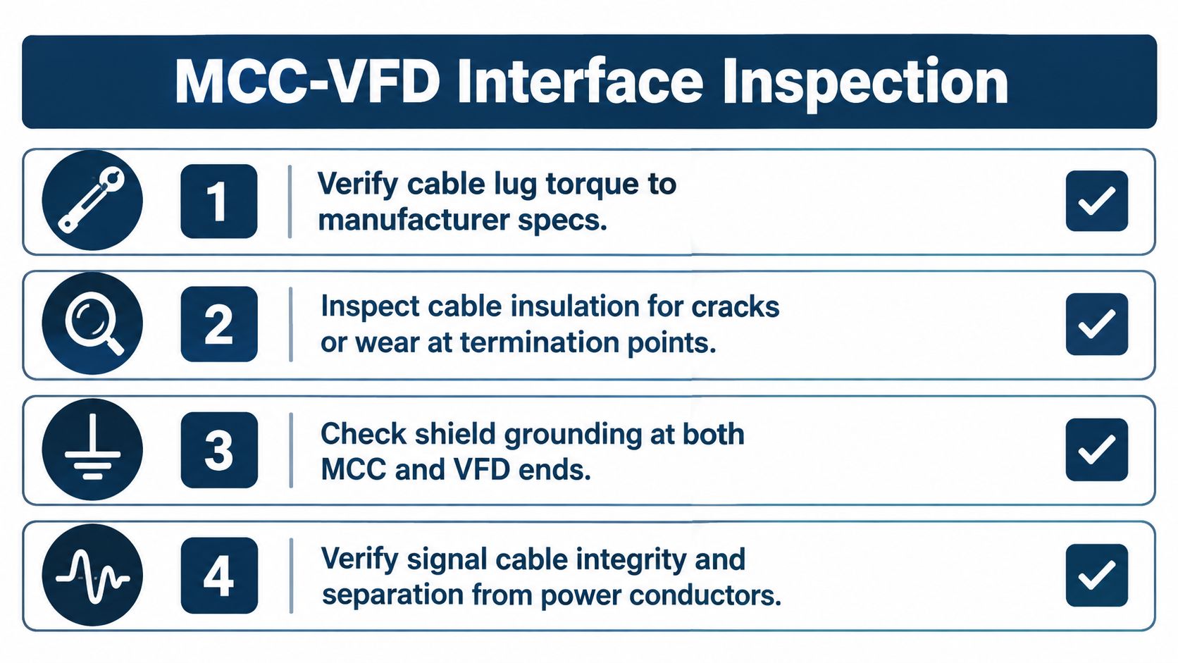
Verify cable-lug torque against the manufacturer's requirements. Use the correct termination style for the terminal and application. Keep conductors fully seated, remove visible strand whiskers, and confirm that the terminal accepts the installed conductor arrangement.
Examine insulation at both ends, especially where cables bend into the bucket or drive. VFD output switching adds electrical stress to the cable system. A termination that looks untidy can become a recurring source of trips, heating, or insulation damage.
Check shielding and bonding with the same care. Confirm the approved shield-termination method, separate drive output conductors from sensitive signal wiring, and verify a clean bonding path to the drive chassis and MCC grounding system. Keep power and communication routing clear at the boundary, not only inside each enclosure.
Keep heat from recycling
Drive compartments need usable airflow and adequate clearance. Check whether exhaust air returns to an intake, whether filters are loaded, and whether adjacent equipment blocks cooling. A drive that trips after the cabinet warms up may have a ventilation problem even when its electrical connections are sound.
Protection coordination also crosses this boundary. Compare the drive's electronic overload, ground-fault, and overcurrent settings with the upstream breaker or fuse arrangement. Confirm that the disconnecting device suits the drive application and that installed settings match the approved design.
Test the interface under operation
After safe re-energization, set the drive to low speed and observe acceleration. Listen for abnormal buzzing from upstream contactors, watch for nuisance trips, and confirm consistent motor response through the operating range. Record contactor noise, acceleration behavior, fault codes, and any change as speed increases.
Review communication and signal wiring separately, particularly where serial networks pass near power conductors. The RS-485 and Modbus maintenance guidance can support diagnosis when communication faults appear after MCC or drive work.
Log every interface finding against both the MCC asset and the VFD asset. Record the affected termination, grounding path, cooling route, or setting, then assign the corrective action to an owner. Otherwise, one equipment record may be closed while the same interface problem remains active on the other.
Adapting the Program for Harsh and High-Duty Environments
A generic annual checklist is a starting point, not a complete reliability program. Steel, tire, chemical, coastal, and dust-heavy plants expose MCCs to different combinations of heat, switching duty, airborne solids, corrosive gases, salt, and process residue. The interval and inspection depth should follow those stresses.
Change the cadence with the environment
Steel and tire operations often place sustained demand on motor feeders and expose electrical rooms to particulate contamination. Use more frequent thermal surveys, inspect high-load terminations closely, and trend insulation condition rather than treating cleaning as the main control.
Chemical facilities need a deliberate response to corrosive gas ingress. Inspect hardware and barriers for attack, verify that ventilation openings aren't creating an intake path for process vapors, and assess whether enclosure modifications or material changes are needed. Legacy equipment with hazardous residues requires a controlled handling decision, not casual wiping.
Coastal installations deserve special attention at copper bus interfaces, breaker terminals, hardware, and bucket stabs. Early corrosion can create resistance that later appears as a thermal imbalance. Re-baseline equipment after corrective work and document the condition of plated surfaces and replacement hardware.
Dust-heavy cement and aggregate sites need source control as much as internal cleaning. Check air-handling performance, differential pressure where the room uses controlled airflow, cable-entry sealing, and the condition of exterior surfaces. A regular exterior wipe-down can reveal how quickly contamination is returning.
| Environment | IR Scan Interval | Contact Resistance | Primary Focus Areas |
|---|---|---|---|
| Steel | Quarterly or more often when load and history justify it | Tighten the interval for high-duty feeders | Heat at terminations, iron oxide, bus insulation trends, switching stress |
| Tire | Quarterly for critical or heavily loaded circuits | Semi-annual focus on high-duty paths | Weld particulate, carbon black, enclosure sealing, cooling paths |
| Chemical | Environment-driven, with shorter intervals where corrosion is active | Increase attention on corroded interfaces | Gas ingress, barriers, hardware condition, residue and moisture |
| Coastal | Re-evaluate thermal baselines every 6 months | Repeat on corrosion-prone terminations | Salinity, verdigris, copper and plated hardware, cabinet sealing |
| Dust-heavy | Frequent scans based on loading and contamination history | Target heat-affected and contaminated connections | Air handling, differential pressure, filtration, exterior contamination |
The specialized guidance on motor control center maintenance in demanding environments supports environment-based intervals rather than a fixed calendar-only program. That approach matters because the same MCC design can need very different attention in a clean indoor room and a particulate-heavy production area.
Control the risk created by maintenance
Maintenance-induced failures remain a central concern. A loose lug left on a re-energized feeder, debris dropped into a cubicle, a missing barrier, or a bucket inserted with misaligned stabs can create a new fault immediately after a service window. The historical failure analysis cited earlier makes disciplined workmanship more than a paperwork preference.
Use double-verified torque values on critical connections, inspect the cubicle before replacing barriers, confirm bucket alignment and interlocks, and perform post-task insulation checks where required by the procedure. Keep photographs and test results with the work order, not in a technician's personal folder.
The annual labor guidance in the APWU MCC preventive-maintenance document illustrates the practical nature of the workload. It lists 1.7 hours per year of routine servicing plus 0.5 hours per year of repair time per machine, or 2.2 total servicing-and-repair hours annually, along with 0.3 hours per year of nonproductive time and 2.5 hours per year of total servicing per machine. Those figures don't describe every modern plant, but they reinforce a useful principle. MCC maintenance is usually brief, repeatable intervention distributed across many assets, not a single heroic outage task.
A strong program adjusts scope when the environment changes, trends findings, and schedules follow-up work before the same defect becomes a trip. DUCHENG Industrial provides multi-brand VFD commissioning, troubleshooting, preventive care, repair, and on-site reconditioning for industrial drive systems, including work during planned shutdowns and controlled recovery after faults.
If your plant needs a coordinated MCC and VFD maintenance plan, DUCHENG Industrial can support inspection, troubleshooting, preventive care, repair, and on-site reconditioning across industrial drive systems. Contact the team to align live diagnostics, shutdown work, corrective actions, and restart verification with your site's operating conditions.