
Master inverter repair service decisions for VFDs. Learn when to repair or replace, manage on-site reconditioning, and set SLAs for plant reliability.
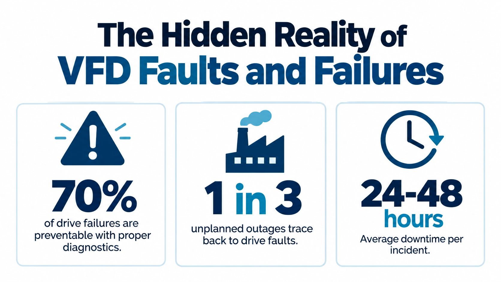
Most plants treat a tripped drive like a one-off electrical failure. That's the wrong frame. One maintenance summary reports that only 33% of VFDs in service have no problems at all, while 67% have undetected faults, and the same source ties nearly 55% of motor failures to overheating while noting that bearing problems contribute to almost half of documented breakdowns in drive-driven systems, which is why serious inverter repair service starts with thermal, contamination, cooling, and mechanical evidence, not guesswork or blind board swapping documented preventive-maintenance statistics for VFDs.
When you manage a plant, the question isn't whether drives fail. It's whether your team catches the fault early, isolates it correctly, and restores the asset without creating a second outage. Good repair practice protects production. Cheap repair practice often just delays the next shutdown.
Table of Contents
- The Hidden Reality of VFD Faults and Failures
- Navigating the Repair Versus Replace Decision
- Mandatory Diagnostic and Triage Protocols
- Workshop Deep Repair Versus On-Site Reconditioning
- Spare Part Verification and Emergency SLAs
- Selecting a Lifecycle Electrical Service Partner
The Hidden Reality of VFD Faults and Failures
Many drives continue running after degradation has started. They can still start, ramp, and hold speed while airflow paths clog, capacitors absorb thermal stress, fans lose efficiency, boards collect conductive contamination, or mechanical problems load the drivetrain. An alarm often marks the final stage of a fault that has been developing for weeks or months.
Faults rarely stay isolated
A nuisance trip may appear to involve one drive. The surrounding conditions often tell a wider story. Dust can restrict cabinet airflow, reducing fan performance and raising internal temperature. Heat then accelerates capacitor aging and stresses power components. At the same time, bearing wear or misalignment can increase motor current and create repeat overload trips that resemble an electronic fault.
A practical triage process follows that chain instead of replacing the first failed part. Record the alarm history, inspect the cabinet and cooling path, check terminals and bus connections, review motor current behavior, and examine the driven equipment. For medium-voltage equipment, safe isolation and on-site condition assessment also determine whether reconditioning can restore reliability without removing the entire asset from service.
That is why inverter repair service belongs within asset reliability planning. A contaminated cabinet can turn a minor airflow restriction into a thermal event, damage several power-stage components, and leave a replacement board exposed to the same cause. Repairing the visible failure without correcting the site condition creates a repeat-outage risk.
Practical rule: If a failed drive comes out of a dirty, hot, poorly ventilated cabinet, assume the environment contributed to the fault until inspection proves otherwise.
What drives repair demand in the field
The work that prevents repeat failures is usually methodical:
- Thermal inspection first: Check for hotspots, discolored terminals, cooked insulation, and restricted airflow.
- Cooling-system checks: Clean fans, assess replacement needs, and verify filters and cabinet ventilation.
- Capacitor condition testing: Inspect DC-link components for aging that can destabilize the power section.
- Bearing-related troubleshooting: Investigate rotating-equipment problems that can appear as overloads, repeat trips, or unclear alarms.
- Contamination assessment: Look for dust, oil, moisture, and conductive residue on boards, heat sinks, and connections.
A strong repair workflow reads the failure backward. It asks what the drive endured over its operating life, which subsystem was stressed, and whether the installation will recreate the same fault after restart.
Why reactive repair costs more than it looks
A rushed restart may recover production briefly while leaving the initiating condition untouched. The result can be repeat outages, emergency callouts, lost troubleshooting time, and unnecessary board changes. The direct repair invoice is only one part of the exposure. Production interruption, specialist access, process disruption, and the risk of another failed start can exceed it.
A professional inverter repair service earns its value through diagnosis, not part-swapping speed. It separates the failed component from the damaged subsystem and from the site condition that caused both. That distinction supports a repair plan based on lifecycle reliability, including on-site medium-voltage reconditioning where the equipment and safety controls permit it.
Navigating the Repair Versus Replace Decision
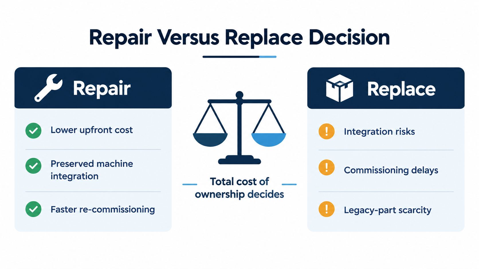
Replacement looks final on a purchase order, but it brings parameter recreation, interface validation, cabinet modification, control integration checks, and restart troubleshooting that may not appear in the initial quote. A repair is not automatically the safer choice either. The decision should follow the asset's condition, failure history, integration risk, and expected service life.
Use lifecycle windows, not instinct
A well-maintained VFD is commonly expected to last about 7 to 15 years. Its maintenance window narrows around 7 to 10 years for capacitor replacement and around 3 to 5 years for cooling fan replacement. Service-life guidance also notes that poor maintenance can reduce a drive expected to last 10 to 15 years to failure in about five years VFD service-life guidance and replacement windows.
These milestones change the repair scope. If the drive is entering a known wear-out period, replacing the visibly failed component alone may leave other aging parts in service. The better question is whether the unit should receive a broader preventive overhaul during the same outage, or whether its condition justifies planned replacement.
If the drive failed near a known fan or capacitor aging window, replacing only the burnt part can become the most expensive cheap decision.
When repair is usually rational
Repair generally makes sense when service cost remains clearly below the combined cost of new equipment and restart work, the installed drive is difficult to access, and the provider includes diagnostics and performance verification. Thermal aging items such as fans, heat sinks, and DC-link electrolytic capacitors are common failure points, but the repair plan should address the stressed subsystem and the condition that caused the failure, not just the damaged part industry analysis of repair economics and service market growth.
Plant teams usually have a strong repair case when:
- Integration risk is high: Machine logic, communications, field wiring, and operator settings are already stable.
- Access is difficult: Removing the drive creates rigging, safety, or outage-planning complications.
- Legacy support matters: The installed unit has a mechanical fit or parameter behavior that a replacement may not match cleanly.
- The failure is diagnosable: The provider can isolate the fault, test the repaired assembly, and verify operation under the required load conditions.
- On-site reconditioning is practical: Medium-voltage equipment can be assessed and reconditioned at the installation, subject to site safety controls, test access, and qualified personnel.
The repair quote should identify what will be tested, what will be replaced, and what evidence will support return to service. A low part price does not compensate for an unverified restart.
When replacement deserves serious consideration
Replacement deserves priority when the asset has repeated unresolved failures, critical modules are no longer supportable, or the plant already needs a broader controls redesign. The purchase price is only one input. Evaluate downtime criticality, spare availability, remaining life, commissioning risk, and the time required to recreate proven operating parameters.
A practical screen helps:
| Asset condition | Repair bias | Replace bias |
|---|---|---|
| Hard-to-access installed drive | Strong | Weak |
| Stable machine integration with legacy controls | Strong | Weak |
| Aging wear parts but repairable core power section | Strong | Moderate |
| Repeated unresolved failures across multiple subsystems | Weak | Strong |
| No credible path to verification after repair | Weak | Strong |
The right choice lowers total operational risk. For a critical drive, that means comparing the repair scope and verification evidence with the replacement outage, integration work, and commissioning exposure, rather than selecting the lowest first quote.
Mandatory Diagnostic and Triage Protocols
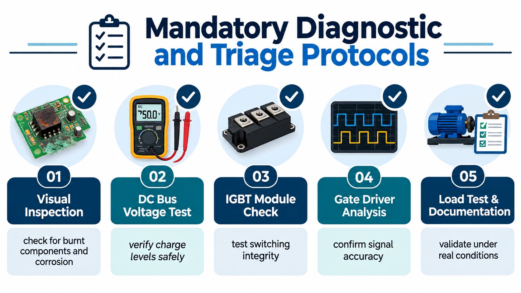
A credible repair provider follows a defined sequence because each skipped step transfers risk to the plant. The most damaging errors are basic: incomplete discharge, premature energization, and teardown before the fault context is recorded. A structured protocol protects personnel, shortens diagnosis, and supports a defensible repair-versus-replace decision.
Start with evidence before teardown
Field repair should begin with full system detection. That includes circuit-aging inspection, module-performance testing, signal-acquisition checks, and power-supply troubleshooting, followed by full-function debugging after replacement. Record alarm codes, fault timing, load state, frequency or speed setpoints, and recent maintenance actions before disassembly. This context helps isolate repeat faults and reduces incorrect component replacement, as described in the documented failure analysis and troubleshooting workflow.
Recording fault context is diagnostic work, not paperwork. It separates a genuine inverter failure from a system fault that only appears at the inverter.
The repair workflow should capture:
- Fault history: Alarm code, trip sequence, load condition, and operator actions immediately before the event.
- Cabinet and environment condition: Contamination, heat stress, loose hardware, moisture, and degraded wiring.
- Aging exposure: Whether the drive is in a wear period that changes the likely failure mechanism.
- System-level plausibility: Whether the reported symptom matches the actual operating scenario.
Before component testing, technicians can use this guide to common VFD fault codes and troubleshooting logic as a reference for interpreting alarm history.
Safe isolation and static testing come first
Begin with safe discharge verification. After shutdown, wait 10 to 15 minutes before measuring the DC bus terminals. Perform diode-mode checks on the rectifier and IGBT stages only after the power section passes isolation checks. A healthy rectifier diode test often shows about 0.3 to 0.5 V forward drop in diode mode, while a zero reading usually indicates a shorted diode, according to the stepwise inverter troubleshooting and diode-test benchmarks.
No technician should open a drive or probe power components until the DC bus has been measured and confirmed discharged. The verification must be documented.
Controlled power-up proves the repair
Test the input and output power sections first. Raise input voltage gradually to rated levels, then complete amp-reading, output-frequency, and jog-function checks. The remaining sequence covers cleaning, inspection, fault finding, replacement of faulty or aged components, load testing, and soak testing on a dedicated rig with an equivalent motor.
Controlled testing exposes faults that a casual bench check misses. A drive may appear healthy at rest, then fail when current, temperature, or switching behavior changes.
Use four release gates:
- Make it safe. Confirm isolation and discharge.
- Prove the power section statically. Inspect and test for obvious shorts before energizing.
- Energize under control. Increase voltage deliberately while monitoring abnormal behavior.
- Validate realistic operation. Load-test, record results, and release the unit only after evidence supports return to service.
This protocol treats the repair as a reliability intervention rather than a component swap. It also gives plant management a traceable basis for judging whether on-site reconditioning or deeper corrective work is appropriate.
Workshop Deep Repair Versus On-Site Reconditioning
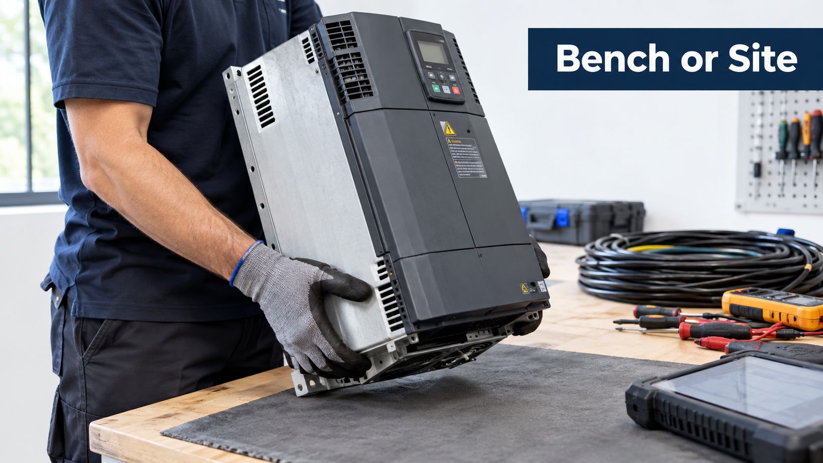
Not every failed drive should leave the site. For smaller, accessible units, workshop repair can be the cleanest route because it allows controlled disassembly, bench diagnostics, component-level work, and repeatable functional testing. For large installed assets, especially medium-voltage equipment, shipping the unit can create its own outage.
What the workshop does better
A workshop environment gives technicians control. They can strip the unit methodically, inspect boards and bus structures under good lighting, clean contamination properly, replace aged components, and run structured post-repair tests without the distractions of an operating plant. When the failure is deep in the power section or tied to multiple suspect assemblies, that controlled environment helps.
Workshop deep repair is usually the better fit when:
- The unit is physically manageable: Removal doesn't create a rigging problem or major line disruption.
- The plant needs board-level analysis: The fault isn't obvious and requires time on the bench.
- Verification needs repeatability: The unit should complete a formal functional test before returning.
What on-site reconditioning avoids
For installed medium-voltage and high-voltage assets, the logistics can dominate the technical decision. Pulling a large drive out, packing it, transporting it, and reinstalling it all create opportunities for schedule slippage, handling damage, and recommissioning errors. In those cases, on-site reconditioning often makes more sense than workshop transfer.
On-site work is especially useful during planned shutdowns when the objective is broader than fixing one failed part. Teams can address cabinet contamination, thermal aging, degraded cooling paths, loose connections, and subsystem wear while the asset stays in place. That's often the smarter path in harsh environments where salinity, conductive dust, or carbon black contamination keeps attacking the same enclosure conditions.
A medium-voltage drive that survives transport still has to survive reinstallation and recommissioning. Plants often underestimate that second risk.
Match the method to the asset, not the habit
A simple comparison helps maintenance leaders choose the right service model:
| Situation | Workshop deep repair | On-site reconditioning |
|---|---|---|
| Small or removable drive | Strong fit | Possible |
| Medium-voltage installed asset | Limited fit | Strong fit |
| Need for cabinet-level remediation | Moderate | Strong fit |
| Need to avoid transport risk | Weak | Strong fit |
| Planned shutdown with multiple aging issues | Moderate | Strong fit |
There isn't a universal answer. The right call depends on asset size, location, voltage class, contamination exposure, and outage window. The strongest plants don't default to one model. They use the one that reduces operational risk while still allowing proper verification.
Spare Part Verification and Emergency SLAs
Many repeat failures get blamed on “bad luck” when the cause is poor spare-part control. A repaired drive comes back online, runs briefly, then trips again because the exchange module was not compatible, the fan was not the correct rating, the capacitor spec was wrong for the duty, or the restored unit was never checked against the plant's operating profile.
Verify parts before they become outage multipliers
Spare-part discipline starts before anyone opens a cabinet. The service team should identify the exact drive model, option boards, firmware context if relevant, power section configuration, and any plant-specific modifications. Then they should verify whether the replacement component is electrically compatible and operationally appropriate for the installed duty.
That sounds obvious. It often isn't done well.
A practical verification process should include:
- Exact asset identification: Nameplate data, installed auxiliaries, and control-side options.
- Failure-linked review: Whether the failed part is likely the root cause or just collateral damage.
- Aging-parts screening: If one wear component failed, decide whether adjacent wear items should be changed at the same time.
- Pre-dispatch confirmation: Check the exchange or replacement item before sending it to site, not after the plant is already down.
- Parameter and program preservation: Make sure the repaired or exchanged unit can return with the right settings and function expectations.
Emergency response needs structure, not a phone number
An emergency SLA for inverter repair service shouldn't stop at “call us anytime.” Plants need a defined restore workflow. When a critical drive trips at night, the first hour matters because confusion multiplies the outage. Operators reset blindly. Electricians arrive without context. The wrong spare gets pulled. Nobody knows whether the load was stable, ramping, or faulted.
A useful emergency protocol defines who records what before intervention. The minimum package should include alarm code, trip timing, load condition, speed or frequency reference, recent maintenance activity, and whether the drive was restarted unsuccessfully. Those details sharply improve first-pass diagnosis.
What to require in an SLA
A workable agreement should spell out response mechanics in plain language:
- Emergency contact path: Who answers after hours, who escalates, and who can authorize mobilization.
- Remote triage expectations: What plant data must be collected before dispatch.
- On-site scope boundaries: Whether the provider is authorized only to diagnose, or to diagnose and attempt controlled recovery.
- Documentation deliverables: Service report, fault findings, replaced components, test results, and restart conditions.
- Restore decision rules: When the drive may be returned to service, when it must be monitored, and when it must stay offline.
The best SLA is the one your night shift can use under pressure. If it isn't operationally clear at 2 AM, it isn't a real outage plan.
Selecting a Lifecycle Electrical Service Partner
A plant shouldn't choose a repair partner the same way it buys a commodity spare. Price matters, but it can't be the lead criterion for a failure-critical asset. What matters more is whether the provider can support the drive across its full operational life, startup, fault response, preventive care, deep repair, reconditioning, and late-life decision making.
What to vet beyond price
Start with technical range. A provider should be able to work across low-, medium-, and high-voltage drive contexts, and it should use a documented diagnostic method rather than technician intuition alone. Ask how they isolate faults before restart decisions, how they verify repaired units, and how they handle contaminated or thermally stressed cabinets.
Then check service reality:
- Regional coverage: Can they reach the site fast enough to matter?
- Multi-brand support: Can they handle the installed mix without improvising?
- Workshop and field capability: Can they do both, or do they force every job into one model?
- Record visibility: Can your team track service history, findings, and open actions?
- Authorized credentials where relevant: Especially when OEM-linked support affects parts or procedures.
One practical benchmark is whether the provider can support more than emergency recovery. For example, DUCHENG Industrial's electrical maintenance contractor approach describes lifecycle support around VFD assets that includes commissioning support, unplanned fault response, workshop repair, preventive shutdown work, on-site reconditioning, spare-part verification, and service record tracking. That kind of scope is often more useful to a plant than a vendor that only appears after a trip.
Choose the team that can explain why the drive failed, how they verified the fix, and what they want changed before the next outage. That's a service partner. The rest are parts changers.
The partner should reduce uncertainty over time
The strongest service relationships create operational memory. They preserve records, trend repeat issues, recognize environment-driven degradation, and help maintenance teams plan interventions before the next forced outage. That's what lifecycle support really means in practice. Not a slogan, just fewer surprises.
If your provider can't show diagnostic rigor, verification discipline, spare-part control, and a realistic field footprint, they're not helping you manage reliability. They're helping you survive the next breakdown.
If your site is dealing with recurring drive trips, aging VFD fleets, or medium-voltage assets that can't be shipped without pain, DUCHENG Industrial can support structured diagnosis, workshop deep repair, on-site reconditioning, spare-part verification, and emergency restore planning across the drive lifecycle. Visit DUCHENG Industrial to review its VFD service scope and decide whether its field and workshop model fits your plant's risk profile.