
Master motor control troubleshooting with a structured VFD diagnostic workflow. Learn fault isolation, test steps, and controlled restart criteria.
The line is down, the operator is waiting, and the VFD display is showing a fault that looks familiar. Someone reaches for the reset button because production pressure makes replacement feel faster than diagnosis. In a harsh plant, that first reset can erase the evidence that would have separated a failed drive from a supply disturbance, a jammed load, a damaged motor cable, or a configuration error.
Effective motor control troubleshooting starts before anyone changes a component. Preserve the first event, establish when and how it occurred, isolate one boundary at a time, and restart only after the cause has been proven. That discipline is especially important in modern facilities, where drives coordinate with automation systems, feedback devices, networks, and demanding mechanical processes.
Table of Contents
- The High Cost of the Quick Reset
- Preserving Evidence and Classifying the Fault
- Dominant Failure Modes and Field Realities
- Executing the Boundary-by-Boundary Test Sequence
- Navigating Configuration and Network Complexity
- Controlled Restarts and Long-Term Reliability
The High Cost of the Quick Reset
A fault reset feels productive because the machine may start again. But a restart doesn't prove the fault is gone. It only proves that the drive accepted another start command.
The first trip often contains the most useful information. The drive may record the active fault, preceding alarms, timestamp, output frequency, current, DC-bus condition, reference source, and operating state. A reset can clear the visible symptom, overwrite the event sequence, or change the process conditions that caused the trip. Once that evidence is lost, the technician is left testing a machine that no longer behaves like the machine that failed.
Practical rule: Treat the first fault as a protected evidence record, not an inconvenience to clear.
Motor control troubleshooting became more systematic as VFDs and digital controllers spread through industrial plants in the early 2000s. The industry moved away from replacing failed components and toward diagnosing configuration, thermal, and coordination problems against measurable baselines, a shift described in this historical account of digital motor control development.
That change matters on the plant floor. A drive can be electrically healthy and still trip because its acceleration time is unsuitable for the load, its reference disappears during a network event, its cooling path is restricted, or its feedback signal becomes unreliable. A motor can also be blamed for a fault caused by a damaged cable, a binding conveyor, or a supply disturbance upstream of the drive.
What the reset hides
A rushed reset commonly destroys three kinds of diagnostic context:
- Sequence evidence: The first active fault may have been preceded by undervoltage, overtemperature, feedback loss, or a communications alarm.
- Operating evidence: A trip during acceleration points toward a different mechanism than a trip after steady operation.
- Process evidence: A jam, valve position, pump condition, or conveyor load may change before the second start attempt.
The technician then sees only the latest symptom. An overcurrent fault after a reset might be caused by a locked rotor, an output short, an overly aggressive ramp, or a mechanical obstruction. Without the original timing and operating state, each possibility remains open.
A better first response
Stop the equipment according to the site procedure, protect personnel, and record the drive state before manipulating controls. Capture the fault code, timestamp, event history, operating mode, speed or frequency reference, current indication, and any available alarm sequence. Photograph the display and cabinet indicators when site rules allow it.
Then ask a narrow question: What changed immediately before the first trip? Was the machine starting, accelerating, decelerating, stopping, or already running? Did the operator report unusual noise, vibration, heat, smell, or process resistance? Those details guide the next test far more effectively than a replacement-first approach.
Preserving Evidence and Classifying the Fault
The technician who opens the cabinet first may be acting quickly, but not necessarily intelligently. Before physical testing begins, preserve the condition that makes the event diagnosable.
Capture the event before touching the system
Use the drive keypad, engineering interface, historian, or approved maintenance record to capture:
- The first fault, not only the latest repeated alarm.
- The timestamp and event order, including preceding warnings.
- The operating phase, such as power-up, enable, acceleration, steady run, deceleration, or stop.
- The drive history, including recent trips, parameter changes, and restart attempts.
- The command and reference path, including local, remote, analog, network, or preset control.
- The process condition, including load position, valve state, conveyor condition, and operator observations.
The sequence is deliberate. A fault that occurs at enable suggests a different boundary than one that appears only as speed rises. A trip at stop may point toward regeneration or deceleration behavior, while a trip after prolonged operation raises thermal and cooling questions.
Assign a fault family
Don't jump from a code directly to a failed part. First place the event in a working family:
- Input supply: Missing phase, supply instability, loose terminations, or an upstream interruption.
- DC bus: Abnormal bus voltage, charging behavior, braking energy, or capacitor-related symptoms.
- Output stage: Inverter switching problems, output imbalance, or a suspected power-device fault.
- Motor and cable: Insulation damage, phase-to-phase faults, ground faults, long-lead effects, or loose motor terminals.
- Mechanical load: Binding, blockage, excessive inertia, misalignment, or a process condition that raises torque demand.
- Thermal: Restricted airflow, blocked filters, cabinet contamination, fan failure, or ambient heat.
- Control and reference: Incorrect parameters, unsuitable ramps, lost enable signals, scaling errors, or feedback problems.
- Communications: Dropped network commands, stale references, unexpected control ownership, or integration faults.
- Internal drive: A fault that remains after external boundaries have been tested and ruled out.
This classification prevents a common mistake: treating every VFD trip as a drive failure. The recommended workflow is to preserve the first fault and prove one boundary at a time under an approved energy-isolation procedure, as outlined in this VFD fault isolation workflow.
Record first, reset once. A controlled restart is a test after diagnosis, not a substitute for diagnosis.
Dominant Failure Modes and Field Realities
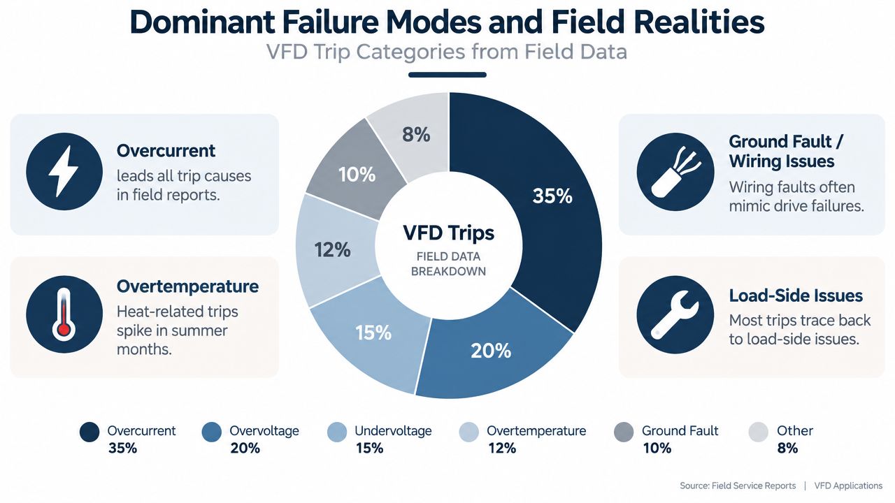
The fault category tells you where to look, but field frequency tells you where to start. Overcurrent is commonly reported as the leading VFD trip category at roughly 30% of trips, while overtemperature is reported at 50% to 60% of VFD issues in one field guide. Those figures point maintenance teams toward heat, overload, misapplication, and load-side conditions before they authorize a power-component replacement, as summarized in this field guide to VFD failure modes.
That doesn't mean the drive hardware is never defective. It means the hardware shouldn't be convicted from the fault label alone. A power module can fail, but recurring overcurrent often reflects a motor circuit problem, a mechanical obstruction, an incorrect motor model, or an acceleration profile that demands more torque than the system can deliver.
Start with heat and load
Thermal inspection should be practical, not ceremonial. Check whether cooling fans run correctly, filters are obstructed, heat sinks are contaminated, cabinet doors seal properly, and nearby equipment is raising the local temperature. Look for dust films, oil residue, corrosion, loose power connections, and signs that heat has been trapped around the drive.
Then compare operating current with the motor and drive application. A current rise during acceleration points toward load torque, ramp settings, or motor parameter issues. A gradual rise during steady operation suggests process loading, bearing friction, airflow loss, or an environmental problem. A sudden rise at a repeatable machine position often implicates the driven equipment rather than the inverter.
Use measurements that answer a boundary question
A measurement is useful only when it helps decide between competing causes. For example:
- Input measurements can show whether all phases remain present and stable under the relevant operating condition.
- DC-bus measurements can indicate whether the rectifier, charging path, capacitors, or regenerative behavior deserves attention.
- Output measurements can expose imbalance, abnormal switching behavior, or a downstream short when taken with suitable equipment.
- Motor tests can identify winding and insulation concerns after the circuit has been made safe.
- Mechanical checks can reveal binding, blockage, misalignment, or excessive resistance that electrical tests won't find.
Field guidance identifies output voltage imbalance above 2% as problematic and output reflections or transients greater than 50% of nominal voltage as problematic. Those benchmarks make cable integrity, motor-lead routing, termination quality, and lead length important parts of VFD troubleshooting, not afterthoughts.
Do not use a standard meter blindly on a PWM output. Use test equipment rated and suitable for the drive waveform, follow the manufacturer's measurement procedure, and respect stored energy in the DC bus.
<iframe width="100%" style="aspect-ratio: 16 / 9;" src="https://www.youtube.com/embed/cMACLA0TOuU" frameborder="0" allow="autoplay; encrypted-media" allowfullscreen></iframe>Executing the Boundary-by-Boundary Test Sequence
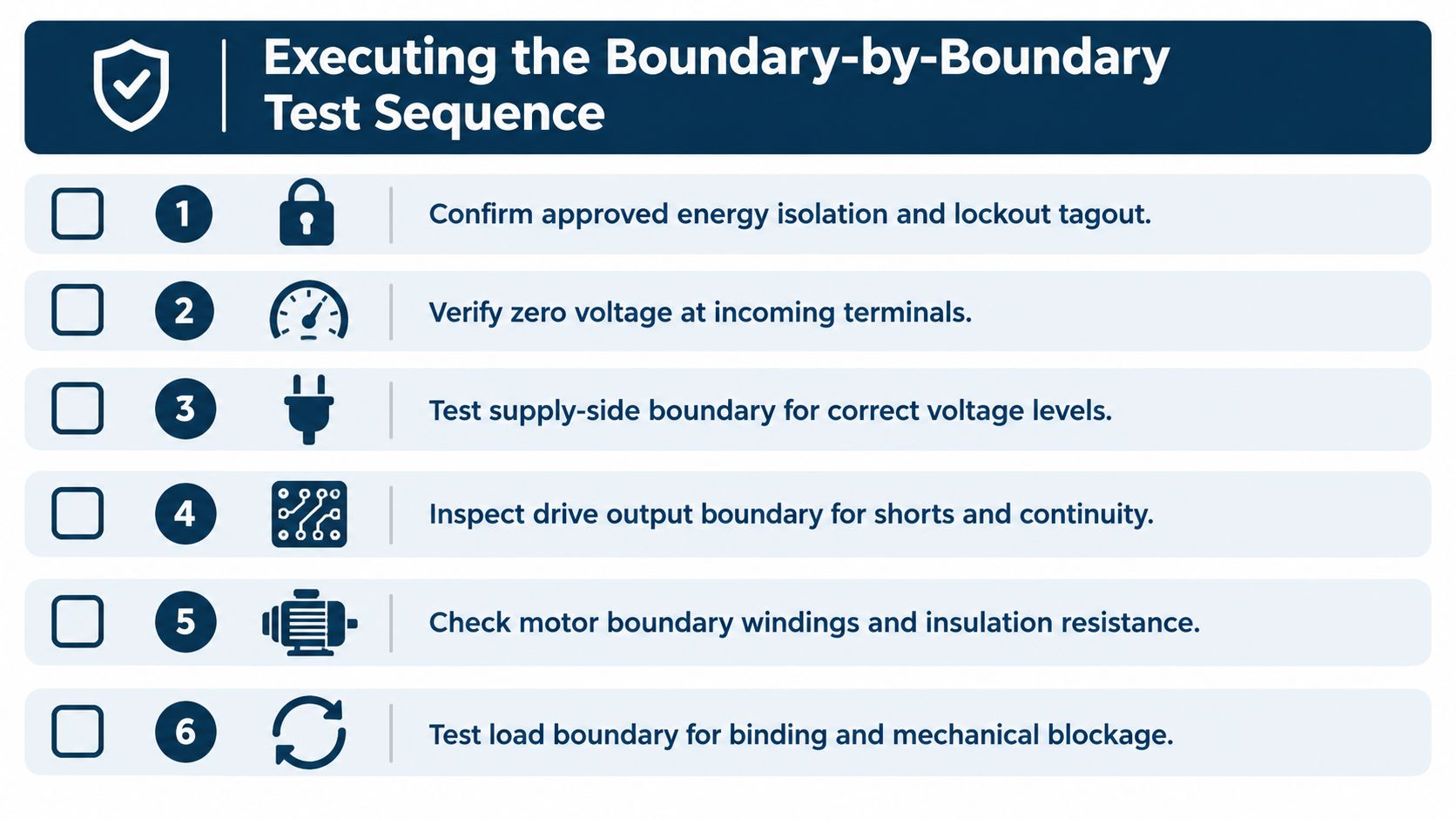
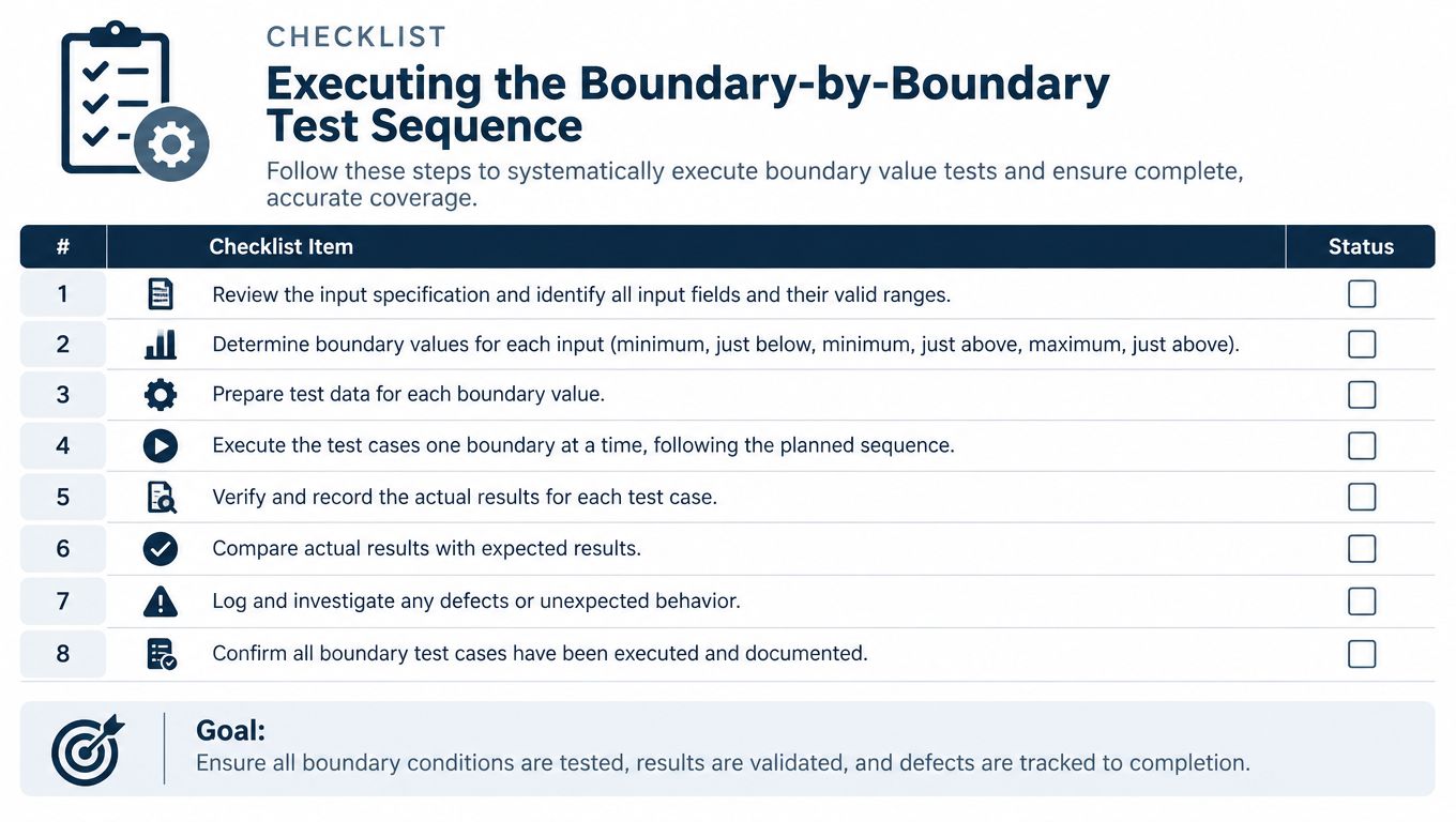
A disciplined test sequence moves from the source toward the load. It prevents technicians from declaring the motor defective before they have proved the supply, or condemning the drive before they have separated the output circuit from the mechanical system.
Establish safety and the incoming boundary
Begin with the approved energy-isolation procedure. Confirm isolation, verify absence of voltage with an appropriate test instrument, and account for stored DC-bus energy according to the equipment procedure. A display that is dark isn't proof of a safe circuit.
Once safe, inspect the incoming terminals, disconnects, fuses, contactors, and terminations. Look for heat discoloration, looseness, corrosion, and evidence of phase loss. Check the supply boundary under the conditions relevant to the fault when the approved procedure allows energized testing. If the trip happened during acceleration, a healthy idle reading may not explain a supply disturbance under load.
Separate the drive from the motor circuit
The next boundary is the drive output. Inspect motor leads, gland plates, terminal boxes, shields, grounding, and cable routing. Search for crushed insulation, moisture ingress, carbon tracking, loose lugs, and contamination around the motor terminals.
A safe isolation test may include phase-to-phase and phase-to-ground checks, continuity checks where appropriate, and insulation testing with equipment and procedures suitable for a VFD-connected motor. Disconnect sensitive electronics before applying an insulation tester, and never assume a test method is acceptable just because it is common on direct-on-line motor circuits.
Test the motor and mechanical load
The motor boundary includes winding condition, insulation, bearings, coupling, brake operation, and shaft freedom. Electrical balance alone doesn't clear the mechanical system. A motor may pass a static test and still trip when a bearing heats, a pump binds at operating position, or a conveyor encounters a blockage.
Prove the load separately where the site procedure permits. Check for physical obstruction, abnormal friction, misalignment, and process conditions that increase torque demand. If the drive trips at a consistent point in the machine cycle, reproduce that condition only under a controlled and authorized test plan.
For teams building a wider electrical maintenance process, this industrial electrical troubleshooting guide provides a related reference point. The principle remains simple: one boundary, one hypothesis, one documented result.
Interpret the result instead of collecting readings
A list of readings isn't a diagnosis. Record the test condition, instrument, point of measurement, and result, then decide what the result rules in or rules out. If the input is sound, the DC bus behaves normally, the motor circuit is intact, and the load turns freely, the remaining suspicion shifts toward output-stage behavior, internal sensing, parameterization, or control integration.
Navigating Configuration and Network Complexity
Many drive trips are difficult because the electrical hardware is only one part of the control loop. The drive may receive its run command from a programmable controller, its speed reference from a network or analog signal, and its feedback from an encoder or process transmitter. A fault can therefore appear at the inverter while the initiating problem sits in the control architecture.
Buyer feedback places the hardest motor control problems in programming or configuration at 53%, control complexity at 50%, and integration with existing automation or networks at 46%, according to this motor and drives buyer study. Those figures explain why a basic checklist of fuses, contactors, and motor windings often fails experienced plant teams.
Verify the control chain
Start by identifying who owns the drive command at the moment of failure. Local keypad control, terminal control, network control, and automatic sequence control can produce very different symptoms. Confirm the active command source, enable state, reference value, direction command, interlocks, and permissives.
Then compare the loaded parameter set with the approved application record. Pay particular attention to motor nameplate data, control mode, minimum and maximum frequency, acceleration and deceleration settings, current limits, torque limits, braking functions, restart behavior, and feedback configuration. A parameter can be valid in isolation and still be wrong for the machine.
A lost reference often looks like a drive failure because the motor doesn't respond as expected. A mismatched acceleration setting may produce an overcurrent trip only when the load is full. An encoder fault may appear as speed instability, excessive current, or a stop command when the actual issue is signal integrity.
Treat network events as physical evidence
Use event timestamps to compare the drive history with the controller, network, and process records. Look for a command drop, reference step, mode change, safety interruption, or loss of feedback immediately before the trip. Don't assume a communications alarm is unrelated just because the drive also reports a current fault.
Modern motor management is moving toward health monitoring and data-assisted diagnosis. Thermal condition, vibration, current behavior, fault history, and operating context can reveal patterns that a single meter reading misses. Industry discussion also points to the limits of traditional motor protection as connected, digitalized systems become more common, a concern described in this overview of modern motor protection.
The practical shift is from asking, “Which component failed?” to asking, “Which signal changed first, and which boundary can prove it?” That question connects configuration records, network events, electrical measurements, and process behavior without treating any one source as complete on its own.
Controlled Restarts and Long-Term Reliability
A restart is successful only when it confirms the repair under controlled conditions. Before enabling the machine, remove the proven cause, verify that all personnel and tools are clear, confirm guards and interlocks, and review the restart plan with operations. The first restart should be deliberate, observed, and limited to the conditions needed to validate the correction.
Don't cycle resets to make the line run long enough for the next shift. Repeated resets can turn a manageable fault into thermal stress, insulation damage, mechanical damage, or a second failure with a less useful record. If the fault returns, preserve the new evidence and compare it with the original event instead of treating the recurrence as a separate mystery.
Decide whether repair or replacement is justified
A repair decision should follow the evidence. Component-level repair may make sense when the external boundaries are healthy and the internal fault is repeatable. On-site reconditioning can be appropriate when transport is impractical or when contamination, cooling defects, and aging require more than a quick board exchange. An upgrade assessment becomes relevant when the drive's control, network, feedback, or environmental requirements no longer match the process.
The decision should also account for spares, compatibility, commissioning records, parameter backups, and the risk of repeating the original failure. Replacing a drive without correcting a hot cabinet, unsuitable motor lead arrangement, binding load, or incorrect control setting just moves the failure into the next operating cycle.
Build reliability from the evidence
Preventive work should target the failure mechanisms found in the field, not just follow a calendar. Review fault histories, cabinet cleanliness, fan and filter condition, terminal tightness, motor insulation, cooling paths, load behavior, parameter changes, and network or feedback quality. Trend the information so a recurring warning becomes visible before the trip.
Reported benchmark data associate properly executed predictive and preventive maintenance with a 35% to 55% reduction in unscheduled downtime and a 40% to 60% extension in VFD service life. The same source reports MTBF of 128,000 hours for a properly maintained drive compared with 41,200 hours under neglected conditions, figures documented in this maintenance and VFD repair benchmark.
A useful maintenance record doesn't end with “drive replaced.” It should state the first fault, operating phase, tested boundaries, measurements, confirmed cause, corrective action, restart observations, and follow-up work. That record gives the next technician a baseline instead of another reset button.
For planned inspections, shutdown support, troubleshooting, and motor control center work, see this motor control center maintenance resource. DUCHENG Industrial also provides multi-brand VFD commissioning, structured on-site diagnosis, workshop repair, on-site reconditioning, preventive care, spare-parts verification, and smart O&M consulting for industrial facilities.
DUCHENG Industrial can help your team preserve fault records, isolate VFD and motor faults safely, execute controlled restarts, and plan preventive work for harsh operating environments. Visit DUCHENG Industrial to discuss troubleshooting, repair, reconditioning, or lifecycle support for your drive systems.