
Learn how permanent magnet motors improve efficiency, reliability, and energy savings in industrial plants. A practical overview for engineers.
A pump skid trips during a hot afternoon shift. The motor hasn't failed outright, but the drive is reporting overcurrent, the cabinet is warm, and the process team wants the line running before the next batch window. At the same time, an energy review shows that several large motors spend most of their lives below full load. Procurement proposes a permanent magnet motor as the efficient replacement. Maintenance asks a more useful question: what happens when the motor, VFD, cooling system, and repair strategy are treated as one asset?
That question matters. A permanent magnet motor can reduce rotor losses, deliver strong low-speed torque, and make direct-drive layouts practical. It can also demand more disciplined commissioning, tighter thermal protection, and a more deliberate plan for diagnosing demagnetization. The right choice isn't determined by the nameplate efficiency alone. It depends on the duty profile, the drive, the magnet grade, the plant's troubleshooting capability, and what you'll do when the rotor or inverter eventually needs service.
Table of Contents
- Why Plant Engineers Are Revisiting the Permanent Magnet Motor
- How a Permanent Magnet Motor Actually Works
- Permanent Magnet Motor Versus Induction Motor
- VFD and Drive Compatibility Essentials
- Magnet Grades, Temperature, and the Demagnetization Margin
- Where Permanent Magnet Motors Earn Their Place in Industry
- Failure Modes and Maintenance That Engineers Actually Face
- A Plant Engineer's Selection Checklist and End-of-Life View
Why Plant Engineers Are Revisiting the Permanent Magnet Motor
A motor retrofit can look attractive on an energy spreadsheet and still create trouble at the first trip. Operations needs production restored, energy managers want lower consumption, and maintenance needs a motor and VFD that can be commissioned, diagnosed, and repaired without specialist delays. A permanent magnet motor can meet the first two demands, provided the third is addressed during specification.
The strongest case appears in duties with long periods at reduced speed or partial load. Permanent magnets create the rotor field without electrical rotor losses, allowing an efficiency advantage where an induction motor continues to dissipate energy in its rotor. An industrial analysis reports an advantage of 4% to 7% across relevant operating ranges. Small motors below 15 kW can reach approximately 10% at 100 revolutions per minute, while the benefit can narrow to about 3.5% at higher speeds. Medium-size machines up to 375 kW typically show a 2% to 4% advantage in that analysis (industrial analysis of permanent-magnet motor efficiency).
Those figures are not a retrofit decision by themselves. Poor hydraulic control, an undersized drive, blocked cooling passages, incorrect motor parameters, or inadequate thermal protection can erase the expected saving. A PM motor also requires a plan for checking current balance, speed feedback, winding temperature, and possible demagnetization after an overload or overheating event. If the plant cannot safely recommission it after a trip, the service risk may outweigh the energy benefit.
Practical rule: Treat the permanent magnet motor as a motor-and-drive system, not as a more efficient drop-in motor.
The technology also reflects a long development path. Early magnetic motor experiments led to Alnico designs, followed by samarium-cobalt magnets in the 1960s and industrial development of neodymium-iron-boron magnets in the 1980s. NdFeB enabled compact, high-strength designs for motors, wind turbines, magnetic bearings, and electric vehicles (history and development of permanent-magnet motor technology).
For plant engineers, the choice is a lifecycle decision. Select PM where part-load efficiency, low-speed torque, and compact direct drive justify tighter control and service requirements. Retain induction, or assess synchronous reluctance, where familiar troubleshooting, simpler control, and repair access matter more than power density. Include rotor handling, magnet-grade behavior, demagnetization diagnostics, and repair-versus-replace costs before approving the retrofit.
How a Permanent Magnet Motor Actually Works
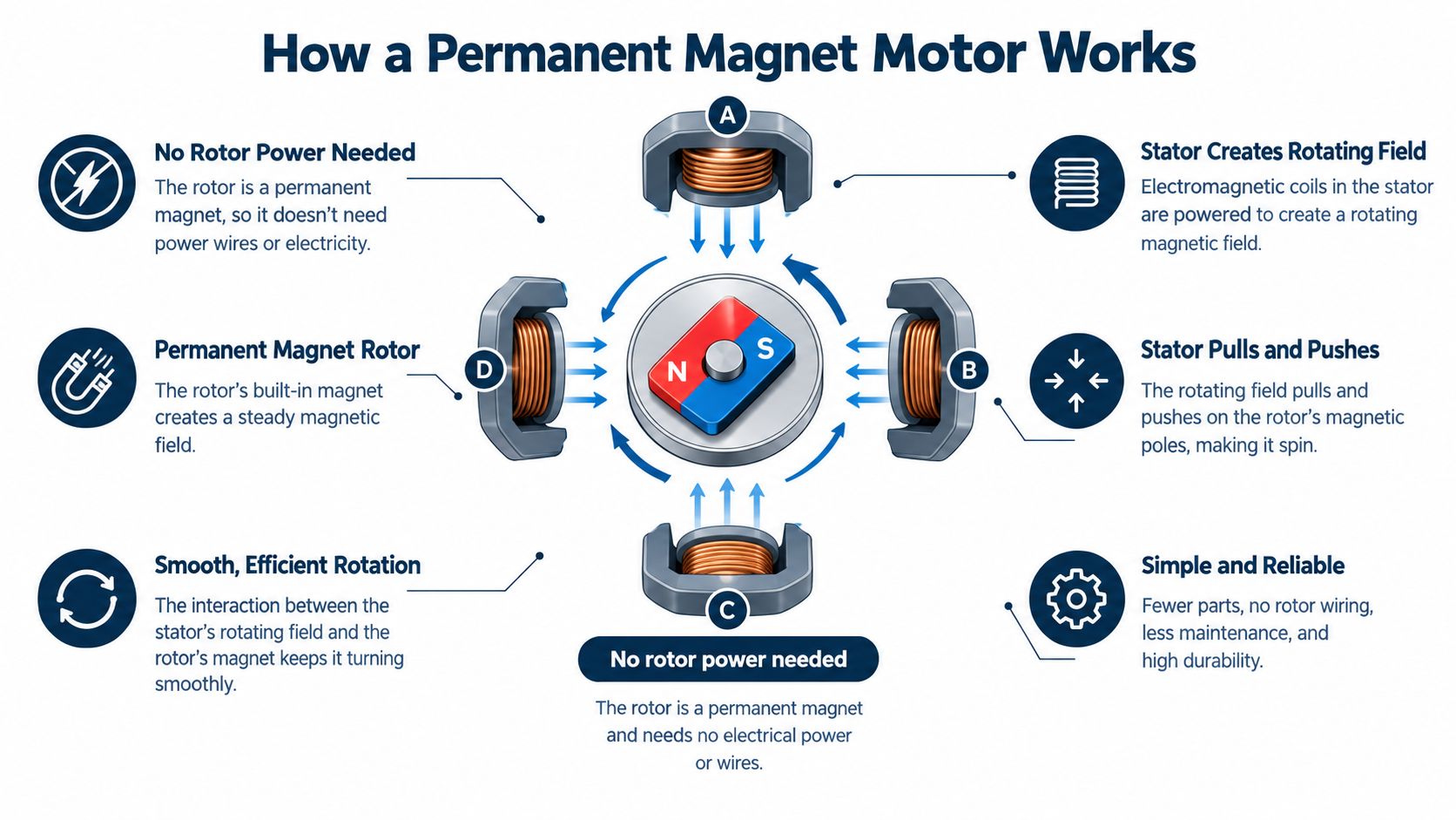
An electric motor produces torque by making magnetic fields interact. The stator stays still and carries the windings. The rotor turns on the shaft and responds to the rotating magnetic field created by the stator.
In an induction motor, the stator field induces current in conductive rotor bars. Those rotor currents create the rotor field, but they also produce rotor copper losses. The rotor must run slightly slower than the rotating stator field to maintain induction. That difference is slip.
A permanent magnet motor replaces the induced rotor field with magnets mounted on the rotor. The magnets are always magnetized, so the rotor doesn't need a separate electrical supply, brushes, or rotor windings. The stator's job is to create a rotating field that pulls and pushes the magnetic rotor around.
The rotor choices
The most common industrial arrangement is the permanent magnet synchronous motor, or PMSM. Its rotor turns in synchronism with the stator field, rather than relying on slip. A surface-mounted permanent magnet rotor places magnets on the rotor surface. An interior permanent magnet rotor places them inside the rotor iron, where the magnetic geometry can also create reluctance torque.
That reluctance component matters. The rotor tends to align with the path of lowest magnetic reluctance, adding torque to the torque produced by the magnets. Interior designs can therefore support strong torque density and controlled high-speed operation, although they also require careful rotor mechanical and electromagnetic design.
Brushless DC motors use a closely related machine concept but typically use trapezoidal back-EMF and six-step commutation. PMSMs generally use sinusoidal currents and field-oriented control. The distinction is less about the presence of magnets than about the motor's back-EMF shape and how the drive commutates the phases.
Why torque density improves
Because the rotor doesn't carry induced current, the motor avoids rotor copper loss. That raises efficiency and permits a compact active design. PMSMs can also deliver strong torque at low speed, and direct-drive arrangements may eliminate a gearbox, reducing mechanical losses and maintenance points.
The trade-off is control sensitivity. An induction motor can tolerate some rotor-position uncertainty because slip is part of its operating principle. A PMSM rotor has a fixed magnetic field. The drive must know the rotor angle well enough to place current in the correct direction, limit demagnetizing current, and manage flux weakening at higher speed. A bad encoder offset or unsuitable sensorless model doesn't just reduce performance. It can produce torque pulsation, overcurrent, or damaging thermal stress.
Permanent Magnet Motor Versus Induction Motor
On a pump that spends much of its shift below full speed, the choice affects more than the motor's nameplate. An induction motor creates its rotor field electrically. A permanent magnet motor carries that field in the rotor magnets. The difference changes operating losses, starting arrangements, drive requirements, cooling, diagnostics, and the options available after a fault.
| Criterion | Permanent Magnet Motor | Induction Motor |
|---|---|---|
| Part-load efficiency | Usually stronger when the motor spends substantial time at reduced speed or load | Rotor losses remain present during operation |
| Low-speed torque | High torque density is available, including in direct-drive designs | Strong performance is possible, but the machine may be larger for the same torque |
| Control | Requires compatible PMSM vector control and accurate motor parameters | Broad compatibility with V/Hz and vector-control methods |
| Starting | Normally coordinated through an electronic drive | Can use established induction starting methods, subject to application requirements |
| Overload response | Current and temperature limits must protect the magnets | No permanent magnetic material can lose magnetization |
| Cooling | Rotor losses are lower, but magnet temperature and stator heat still matter | Rotor heat is generated internally and can be harder to remove |
| Serviceability | Rotor condition, magnet strength, feedback, and drive settings need specialist attention | Familiar inspection and repair methods are widely available |
| Direct drive | High low-speed torque can make gearbox removal practical | May require a larger motor or retained gearbox for the same duty |
Efficiency is the easiest PM advantage to quantify. Independent testing summarized by the American Council for an Energy-Efficient Economy found small-horsepower permanent-magnet motors to be 2% to 26% more efficient than comparable induction motors over the same operating-load range, with the largest savings in HVAC equipment, compressors, pumps, and fans that often run at reduced speed or partial load. The saving depends on the complete operating profile, not one rated point.
Where induction still makes sense
An induction motor remains attractive when rugged simplicity matters more than compactness. A plant with established spare rotors, familiar rewinding contractors, standard drives, and frequent field repairs may accept higher operating losses in exchange for faster recovery after failure.
Induction machines also avoid permanent-magnet demagnetization. They can still suffer winding faults, bearing damage, rotor-bar problems, inverter stress, and thermal overload. The technician does not have to determine whether the magnetic material has crossed an irreversible operating limit.
Repair economics can favor induction motors even when a PM unit uses less energy. Rewinding, bearing replacement, and rotor work are familiar services for induction machines. A PM repair may require specialist rotor handling, magnet-strength assessment, feedback checks, and a decision between remagnetizing, replacing the rotor, or replacing the complete motor.
Choosing on duty, not nameplate
A PM motor usually wins when it runs for long periods at partial load, needs high torque in a compact package, or can eliminate a gearbox. An induction motor remains compelling when the load is harsh and unpredictable, a replacement drive may be whatever is available, or the maintenance model depends on conventional rotating-machine repair.
Compare energy use, drive compatibility, cooling, spares, diagnostic tools, rotor access, and restart risk against the actual duty. Include the cost of a demagnetization investigation and the plant's repair-versus-replace response before approving the motor.
VFD and Drive Compatibility Essentials
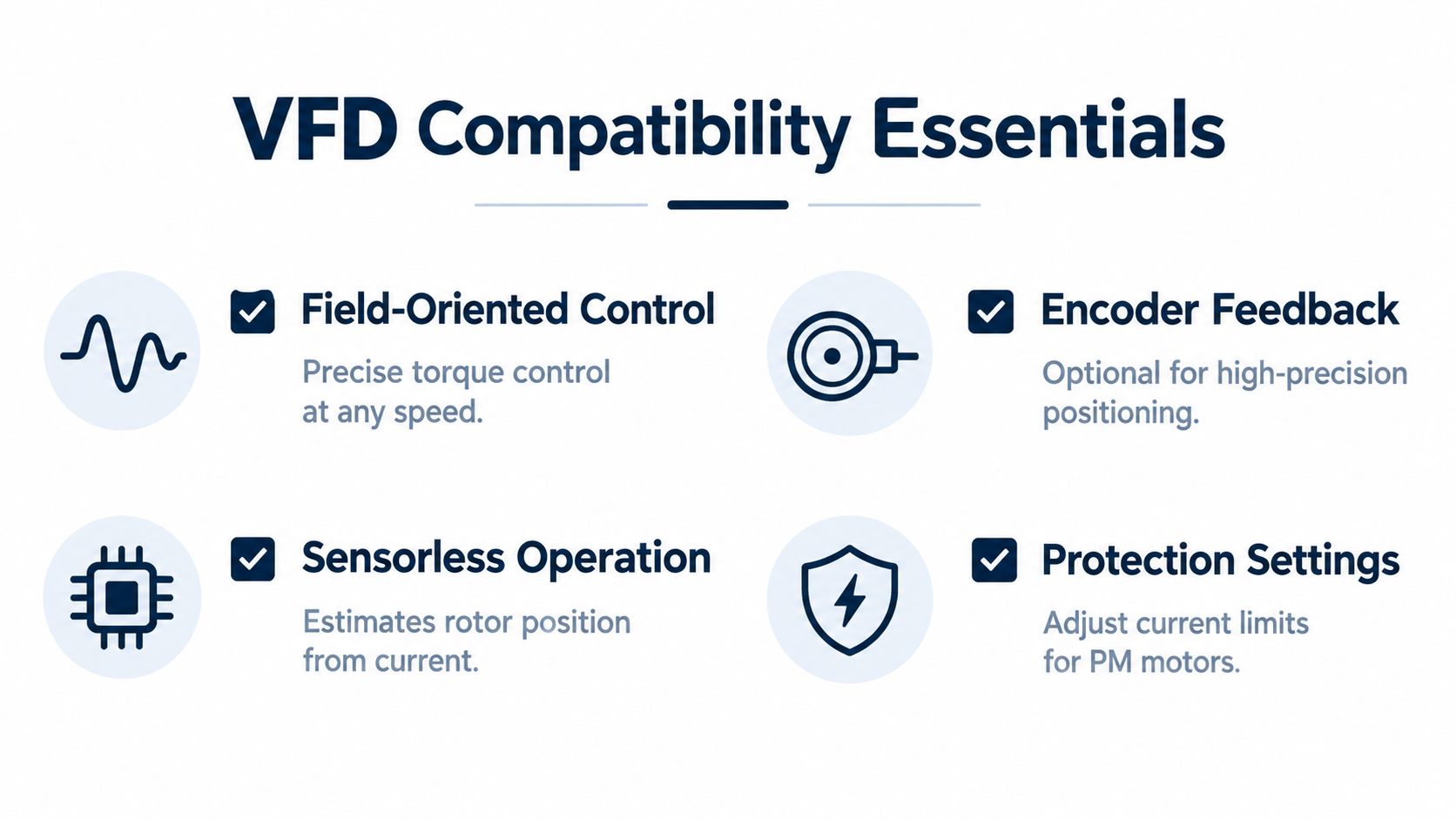
A permanent magnet motor generally shouldn't be treated as an induction motor with a different nameplate. The drive must support PMSM control, whether through dedicated firmware, an appropriate control card, or a native vector-control function. A legacy V/Hz drive that regulates frequency and voltage isn't an adequate default for a magnet rotor.
The drive controls the stator current in relation to rotor position. With an encoder or resolver, it receives direct position feedback. With sensorless control, it estimates rotor position from electrical behavior, typically within a defined speed and load range. High-precision positioning and difficult low-speed starting conditions may justify feedback even where sensorless operation is technically possible.
Before the first start command, verify:
- Motor identity: Enter the correct rated voltage, current, frequency, speed, pole information, and motor resistance or inductance data where required.
- Rotor position: Confirm encoder type, direction, pulse configuration, resolver settings, and encoder offset. A wrong offset can command torque in the wrong direction.
- Drive capability: Confirm that the installed firmware and hardware support PMSM vector control, not only induction-motor control.
- Current limits: Set continuous and transient current limits to the motor and magnet grade, not to a generic drive default.
- Acceleration: Start with a controlled ramp that matches the load inertia and avoids unnecessary torque transients.
- Thermal model: Configure stator protection and, where supported, a rotor-temperature or magnet-temperature estimation model.
- Flux weakening: Confirm the high-speed operating envelope and the negative d-axis current limits. Excessive flux weakening can create demagnetizing stress.
- Mechanical condition: Check shaft alignment, coupling condition, bearings, brake release, and free rotation before energizing.
A useful reference on the distinction between VFD control approaches is this guide to VFD control methods. It should support, not replace, the motor and drive manufacturer's commissioning data.
The first run should be staged. Uncoupled rotation, low-speed direction verification, current observation, encoder validation, and controlled load application reveal errors before the motor sees a severe transient.
A short technical demonstration can help teams visualize the interaction between the drive and the motor, but it shouldn't be used as a substitute for the actual parameter sheet.
<iframe width="100%" style="aspect-ratio: 16 / 9;" src="https://www.youtube.com/embed/fWur8C_1xYI" frameborder="0" allow="autoplay; encrypted-media" allowfullscreen></iframe>If the drive can't identify the motor correctly, stop the commissioning sequence. Repeated trial starts are not a tuning method for a permanent magnet rotor.
Magnet Grades, Temperature, and the Demagnetization Margin
Magnet selection sets more than torque density. It determines the thermal and overload margin available before the rotor loses magnetic performance permanently, which affects both VFD settings and repair decisions.
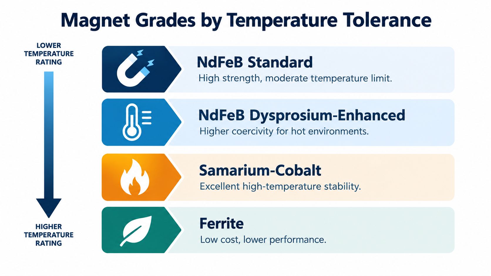
NdFeB magnets provide high remanence and compact torque production, but their performance falls as operating temperature rises above approximately 100 °C. High-coercivity grades with heavy rare-earth additions, such as dysprosium, can retain approximately linear magnetization up to about 175 °C, as shown by the B-H curves in the magnet temperature and demagnetization analysis. Confirm the selected grade's temperature limits against the manufacturer's datasheet rather than applying a generic NdFeB value.
Samarium-cobalt magnets resist demagnetization well and suit demanding thermal duties. Their selection still requires checks on cost, availability, rotor construction, and the complete load cycle. Ferrite magnets avoid rare-earth materials and cost less, but their reported coercivity is roughly one-fifth of NdFeB. They therefore have less tolerance for irreversible demagnetization under high demagnetizing fields and high temperature. The comparison should be verified against the relevant peer-reviewed ferrite demagnetization data, including its test conditions and figure context.
Rotor temperature is the critical variable
A stator temperature sensor helps, but it does not measure magnet temperature directly. Stator current, blocked ventilation, high ambient temperature, flux weakening, and overload can heat the rotor while the stator reading remains within its alarm limit.
The magnet's knee point marks the boundary beyond which the magnetic operating point may not recover after the stress ends. Below that point, a temporary thermal or electrical event can cause reversible performance loss. Above it, magnetic strength can decline permanently.
Protection settings must match the magnet grade, cooling arrangement, duty cycle, and expected transient current. Copying a generic stator alarm from an induction motor manual leaves the rotor's demagnetization margin unprotected.
Estimating magnet condition without a rotor sensor
Some drives estimate magnet temperature from the d-axis current response using a motor-specific lookup table. Changes in magnetization alter the electrical response, allowing the controller to estimate a temperature or magnet-strength trend without a rotor sensor.
This method depends on an accurate motor model and trustworthy operating data. Record current, speed, load, stator temperature, drive alarms, and cooling status together. A rising temperature estimate combined with higher current at the same process load warrants investigation before a trip occurs. Compare the trend with commissioning records before deciding whether the problem is cooling, tuning, overload, or permanent magnet damage.
Where Permanent Magnet Motors Earn Their Place in Industry
The strongest PM applications have a repeatable duty pattern. They run for long periods away from full load, need high torque at low speed, or benefit from removing a gearbox.
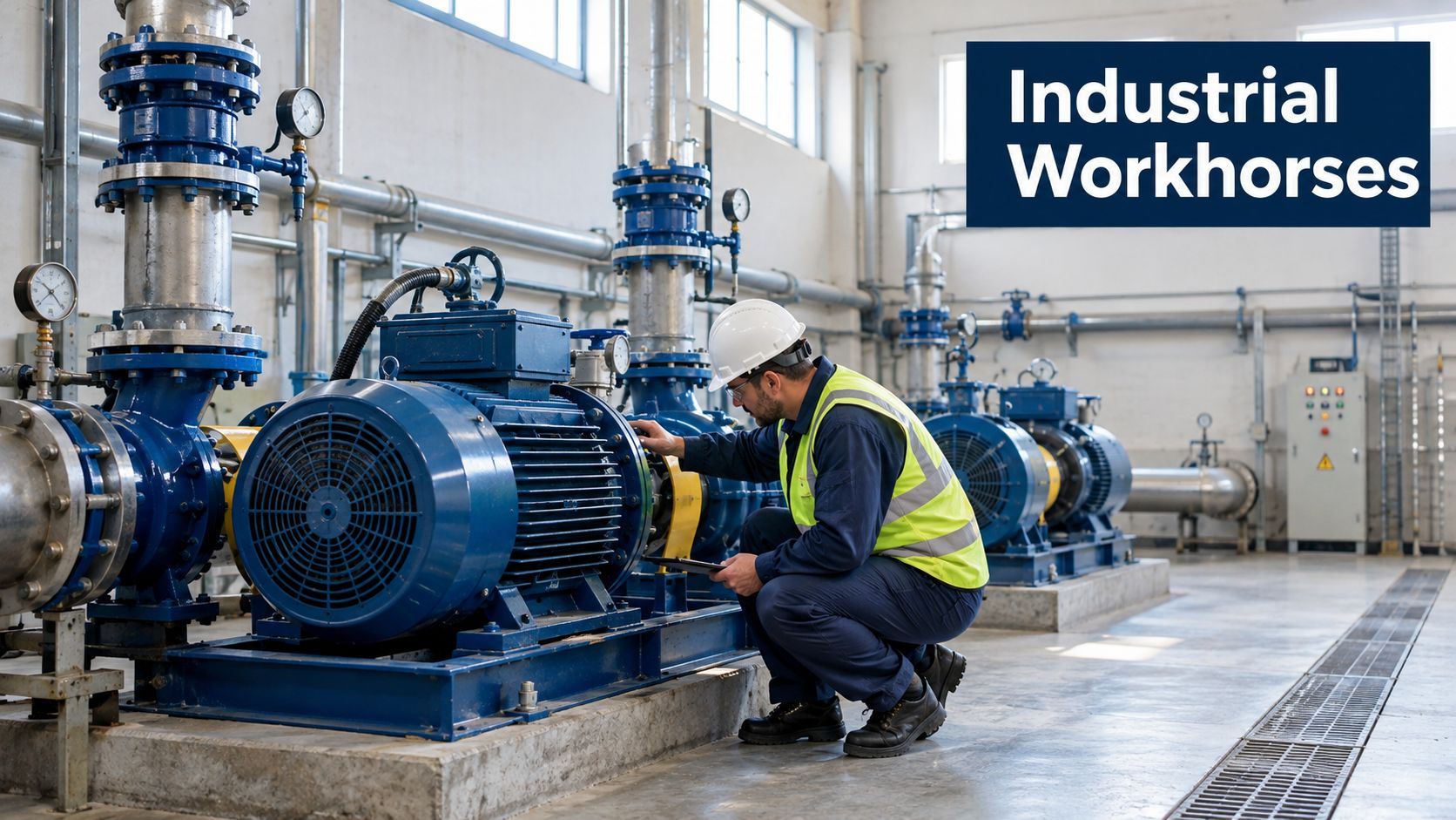
Pumps and fans are natural candidates when the process varies frequently. A VFD can reduce speed, and the permanent magnet motor can avoid some of the rotor losses that remain in an induction motor. Cooling towers, circulation systems, and process fans can benefit when the motor spends substantial time at reduced output. The pitfall is poor control logic. If the valve, damper, or process constraint keeps the motor near full speed, the energy case may be weaker than expected.
Compressors and chillers need closer review. A PM motor can deliver efficient operation across changing duty points, but repeated starts, high torque demand, inadequate cooling, or aggressive flux weakening can narrow the demagnetization margin. The drive, compressor map, and thermal system must be evaluated together.
Extruders, mixers, and low-speed conveyors can justify a PM design through torque density. In a direct-drive arrangement, the motor may remove a gearbox and its lubrication, alignment, and bearing requirements. That advantage disappears if the PM motor needs a specialist rotor repair that the plant can't support.
Conveyors with frequent starts can use PM motors effectively, but only when acceleration torque, stopping behavior, brake coordination, and current limits are correctly configured. Blocked conveyors and jam events are particularly important because a short high-current event can create a demagnetizing field even when the average load looks normal.
When another technology is safer
An induction motor may be the better choice for a duty with severe mechanical abuse, uncertain overloads, limited drive support, or a strong requirement for local repair. Synchronous reluctance can also be attractive where the plant wants reduced rotor losses without permanent magnets, although its own motor and drive selection requirements still need review.
The selection should follow the process, not the technology trend. Map speed, torque, starts, overloads, ambient conditions, cooling, and maintenance access before choosing the rotor type.
Failure Modes and Maintenance That Engineers Actually Face
Permanent magnet motors aren't maintenance-free. They have fewer rotor electrical losses, but they add failure modes that can be misread as inverter, encoder, bearing, or stator faults.
A practical diagnostic sequence starts with symptoms:
- Rising current at the same load: Check process load, phase-current balance, encoder alignment, stator insulation, cooling, and possible magnet-strength loss.
- Torque pulsation at specific speeds: Inspect feedback integrity, encoder offset, mechanical alignment, bearing condition, and control tuning.
- Repeated overcurrent trips: Review acceleration, blocked-rotor events, current limits, flux weakening, and motor identification data before condemning the rotor.
- Gradual efficiency loss: Compare historical current, speed, load, temperature, and back-EMF data rather than relying on one alarm.
- Abnormal shutdown measurements: A controlled back-EMF test can help identify reduced magnetic flux, but interpretation requires a known test procedure and safe isolation.
Insulation testing, phase resistance, current signature, encoder checks, vibration readings, and drive-event review can usually be performed in situ. Rotor removal is generally required for direct magnet assessment, mechanical inspection, or bench measurement of residual magnetic field.
Thermal demagnetization can result from excessive temperature, cooling failure, flux weakening, inter-turn faults, or aging. Partial damage may degrade performance without producing an immediate trip, so a motor can continue running with rising energy use, vibration, or process instability (practical demagnetization diagnosis research).
Use a documented repair pathway rather than replacing the motor on the first suspicion. A structured industrial motor repair process should separate electrical faults, drive faults, mechanical faults, and permanent magnetic damage before a rotor decision is made.
Contamination and blocked ventilation deserve the same attention as an overload alarm. Slow thermal damage often starts as a cooling problem, not a dramatic motor failure.
A Plant Engineer's Selection Checklist and End-of-Life View
A permanent magnet motor is a strong candidate when the duty rewards part-load efficiency, low-speed torque, compactness, or direct drive. Before approving it, confirm the PMSM control capability, feedback method, current limits, cooling design, magnet grade, rotor-temperature strategy, spare motor or rotor plan, and local repair capability.
Don't ignore the end of life. Rare-earth magnets, bonded materials, rotor assemblies, and contaminated laminations require separation and assessment. A 2025 study proposed a multi-stage process for extracting rare-earth magnets from end-of-life vehicle drives, showing that recovery remains an active engineering problem rather than a universal routine (research on rare-earth magnet recovery). Compare repair, rotor remanufacture, magnet harvesting, and replacement against downtime, safety, traceability, and lifecycle cost. The highest-efficiency motor isn't automatically the lowest-impact asset if nobody can service or recover it responsibly.
DUCHENG Industrial supports plant teams with multi-brand VFD commissioning, troubleshooting, repair, on-site reconditioning, spare-parts verification, and lifecycle upgrade assessments. If your permanent magnet motor project depends on a reliable drive setup and a disciplined response to future trips, contact DUCHENG Industrial to discuss commissioning, maintenance, or repair support.