
Choose the right predictive maintenance sensors for rotating assets, drives, and harsh environments. Covers vibration, thermal, current, and signal chain tips.
A motor on a critical line rarely announces its failure in a way a maintenance calendar can understand. It may continue running while a bearing develops a defect, a coupling loses alignment, or a VFD-driven load starts operating under abnormal electrical stress. By the time the motor trips, the team is no longer managing degradation. It's managing production loss, emergency access, spare-part availability, and a repair under pressure.
Predictive maintenance sensors can provide earlier evidence, but only when the complete signal chain works. The sensor type matters. So do mounting, location, cable routing, conditioning, calibration, data governance, and the way alerts reach the people who must act on them. Industrial teams often spend too much time comparing hardware and too little time deciding whether the installed signal will be trustworthy.
The practical rule is simple: instrument the failure modes that matter, install the sensing chain correctly, establish a healthy baseline, and prove that the resulting alert can support a maintenance decision.
Table of Contents
- When Sensors Become the Difference Between a Planned Stop and a Surprise Shutdown
- How Predictive Maintenance Sensors Turn Physical Change into Actionable Signals
- The Five Core Sensor Modalities and What Each One Actually Detects
- Mounting, Location, and Signal Conditioning Decisions That Decide Data Quality
- Matching Sensors to Monitoring Architectures from Edge to Cloud
- Data Quality, Calibration, and Sensor Governance in Harsh Environments
- A Realistic Retrofit Path for Legacy VFDs and Critical Motors
- Your Sensor Selection Checklist Before the Next Shutdown Window
When Sensors Become the Difference Between a Planned Stop and a Surprise Shutdown
A 75 kW motor on a bottling line trips on a Thursday night. The motor drives a critical conveyor, so the line stops with it. The maintenance team finds a damaged bearing, but the replacement has to be sourced urgently, access is limited, and the repair takes fourteen hours of lost production. The scheduled maintenance program didn't prevent the event because its interval was based on elapsed time, not on the motor's actual condition.
A modest predictive maintenance sensor arrangement could have changed the response. Rising vibration would have indicated mechanical deterioration, while a developing increase in bearing temperature would have added confirmation. The team could then have planned a bearing change during an available production window, prepared the correct parts, and inspected the surrounding coupling and shaft alignment without the pressure of a live outage.
Why calendar maintenance misses the real condition
Time-based maintenance is still appropriate for tasks such as lubrication, inspection, cleaning, and safety testing. It becomes less effective when the failure rate depends heavily on load, contamination, alignment, operating temperature, installation quality, or process conditions. Two nominally identical motors can experience very different stress histories.
Predictive maintenance changes the question from “Is it time to replace this component?” to “What evidence shows that this component is degrading?” That distinction protects usable component life while giving the team a warning that can be tied to a work order.
Practical rule: A sensor alert has value only when the site has a defined response, an owner, and enough lead time to act.
The broader industrial adoption of sensor-driven maintenance reflects that operating logic. A 2026 summary of predictive maintenance statistics reported that 30-40% of manufacturing facilities use IoT sensors to collect data for predictive maintenance, while 25-35% of predictive maintenance initiatives use AI or machine learning to analyze those sensor streams. The same source reported typical reductions of 20-30% in overall maintenance costs, 15-25% in unplanned downtime costs, and 22-28% in repair costs for predictive maintenance programs. These figures describe reported program-level outcomes, not an automatic return from installing a sensor on every asset.
The engineering decision comes first. Identify the asset whose failure creates the greatest operational consequence, map its credible failure modes, and select signals that can detect those modes early enough to change the maintenance plan.
How Predictive Maintenance Sensors Turn Physical Change into Actionable Signals
A bearing defect begins as a physical change. A rolling element may create repeated impacts against a damaged raceway, producing vibration energy that travels through the bearing housing and motor structure. The sensor doesn't “see” bearing wear directly. It converts that mechanical energy into an electrical signal that another system can process.
A stethoscope offers a useful analogy. A clinician hears a chest sound, but the sound becomes meaningful only through comparison with a healthy pattern and knowledge of what abnormal sounds imply. A vibration waveform works the same way. A single number rarely explains the fault. The trend, frequency content, operating context, and comparison with a known baseline provide the diagnostic value.
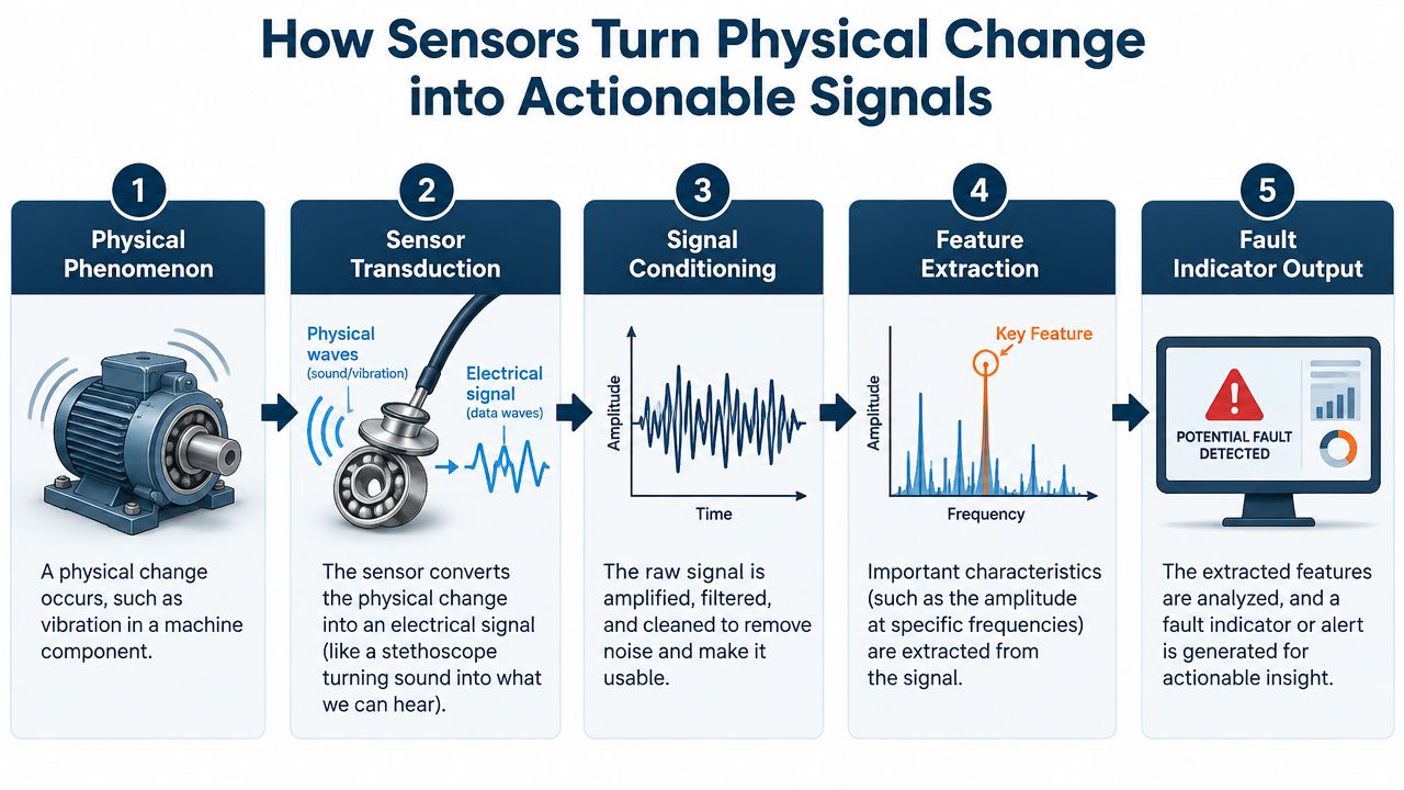
The signal chain in practical terms
- Physical phenomenon: A bearing, shaft, winding, enclosure, or lubricant changes condition.
- Sensor transduction: An accelerometer, RTD, current transformer, humidity sensor, or other device converts that change into an electrical output.
- Signal conditioning: The system amplifies, filters, isolates, and prepares the signal for acquisition.
- Feature extraction: Software calculates trends, spectra, temperature rise, current imbalance, or other useful indicators.
- Fault output: A threshold, rule, or model compares the new evidence against a baseline and generates an alert or maintenance recommendation.
Vibration measurements can cover a range from sub-Hz to kHz depending on the application, which is why accelerometers are useful across bearing defects, imbalance, misalignment, looseness, and gear problems. The Frontiers mechanical-engineering study also emphasizes that installation quality, environmental noise, mounting method, location, and bandwidth must be engineered alongside the analytics.
A threshold is useful for a clear operating limit, but degradation often develops gradually. Baseline spectra and trend analysis can reveal a changing fault signature before a simple overall alarm becomes active. The sensor is therefore only the first link. The value comes from preserving the right signal, comparing it consistently, and routing the result into a decision process.
The Five Core Sensor Modalities and What Each One Actually Detects
Sensor selection should begin with failure modes, not with a catalogue of devices. Vibration, temperature, current, humidity, and particulate sensing each answer a different question, and none should be treated as a universal machine-health instrument.
| Modality | Primary Fault Families Detected | Typical Mounting | Known Blind Spots |
|---|---|---|---|
| Vibration | Bearing wear, imbalance, misalignment, looseness, gear and coupling problems | Stud, adhesive, or industrial magnetic mounting on a bearing housing | Poor mounting, low bandwidth, structural resonance, and non-mechanical faults |
| Temperature | Overheating, lubrication decline, overload, poor ventilation, electrical hot spots | RTD or thermocouple at a bearing, winding, cabinet, or measured surface | Slow response, ambient influence, and limited ability to identify the root cause |
| Current | Load change, phase imbalance, electrical stress, rotor and winding-related anomalies | Current transformer or compatible electrical transducer in the feeder or cabinet | Operating-state dependence, switching noise, and weak resolution for some mechanical faults |
| Humidity | Moisture ingress, condensation risk, insulation stress, and corrosion conditions | Electrical cabinet, enclosure, or breathing path | Environmental exposure does not prove that internal equipment damage has occurred |
| Particulate | Contamination in lubricant, hydraulic fluid, or the surrounding cabinet environment | Fluid circuit, filter point, enclosure, or sampling location | It describes contamination conditions rather than directly diagnosing every asset fault |
Vibration remains the primary mechanical signal
Vibration is usually the strongest first choice for rotating assets because it can reveal mechanical deterioration before temperature or process variables move materially. It's particularly useful for bearings, imbalance, misalignment, looseness, and gear defects. But an accelerometer mounted on a thin guard or painted, corroded surface can produce misleading data, regardless of how capable the analytics are.
Temperature provides confirmation rather than a complete diagnosis in many motor applications. A rising bearing temperature may support a vibration indication, while motor or cabinet temperature can expose overload, poor ventilation, lubrication problems, or electrical connection issues. A single surface-mounted RTD shouldn't be sold as a complete bearing-failure prediction system.
Electrical and environmental signals cover different risks
Current monitoring can identify changes in electrical behavior and load, and it may reveal issues that a mechanical sensor can't. It also depends strongly on operating state, drive behavior, switching effects, and the quality of the installation. Humidity sensing is valuable where condensation, salinity, or enclosure exposure can threaten insulation and metalwork, but it indicates environmental risk rather than proving a particular component has failed.
Particulate monitoring has a similar boundary. It can expose contamination in hydraulic or lubrication systems and help explain accelerated wear, but it doesn't directly measure shaft alignment or bearing impact energy.
For harsh industrial sites, combine modalities deliberately. Vibration can provide the early mechanical warning, temperature can confirm thermal stress, current can add electrical and load context, and humidity or particulate data can explain environmental causes. A condition-monitoring framework for industrial equipment should therefore map each signal to a specific failure mode and response action rather than count sensors as a measure of program maturity.
Mounting, Location, and Signal Conditioning Decisions That Decide Data Quality
The sensor model can't rescue a poor mechanical installation. On rotating equipment, the path from the fault to the sensor determines which frequencies survive and how much plant noise enters the measurement.
Start with the mechanical interface
A permanently installed accelerometer should generally use a rigid stud mount where the asset, access, and maintenance procedure support it. Stud mounting offers a repeatable mechanical path and is usually preferable for high-frequency bearing analysis. Adhesive or epoxy mounting can work for retrofit situations when drilling or tapping isn't practical, but surface preparation must remove paint, rust, oil, and loose scale. Magnetic mounting is convenient for temporary routes and walk-around checks, but it can shift, lose repeatability, or attenuate higher-frequency content.
Place the sensor on the bearing housing or a structurally representative bearing pedestal, as close as practical to the load path. Motor-frame measurements may be adequate for broad trending, but they can hide local bearing behavior. Orientation matters too. Radial measurements are often useful for imbalance, looseness, and bearing behavior, while axial measurement can support alignment and thrust-related investigation. A triaxial sensor can reduce the risk of missing a fault direction, but it also increases data and installation requirements.
Mounting is part of the measurement. Treat the mounting surface as carefully as you treat the sensor specification.
Protect the electrical signal
VFD environments create a difficult electrical neighborhood. High switching edges, motor cables, grounding differences, and cabinet noise can corrupt low-level transducer outputs. Route sensor cables separately from motor and output cables wherever possible. Use suitable shielded twisted pair, establish a deliberate panel-side reference, and avoid creating a second unintended ground path at the motor.
IEPE sensors require a compatible constant-current supply and stable signal conditioning. Voltage-mode outputs need an appropriate input impedance, shielding arrangement, and noise evaluation. A 4-20 mA signal is often easier to integrate into conventional control infrastructure, but it may not preserve the waveform detail needed for advanced vibration diagnostics.
Filtering and sampling deserve the same scrutiny. Excessive low-pass filtering can remove bearing-fault content, while insufficient filtering can allow aliasing. Gain must keep meaningful events above the noise floor without clipping during transients. Before commissioning, verify the complete chain with a known signal or calibrated reference, not just a dashboard value.
| Asset class | Recommended mounting | Cable and shielding | Conditioning note |
|---|---|---|---|
| Critical motor and drive-end bearing | Rigid stud mount on the bearing housing, with radial and axial coverage as required | Shielded twisted pair routed away from VFD output cables | Preserve high-frequency content and verify IEPE supply if applicable |
| Legacy motor with limited access | Prepared epoxy mount, or temporary magnetic mount for route validation | Short, secured cable with panel-side shield reference | Confirm repeatability before using trends for decisions |
| Gearbox and driven fan | Housing location near the load path, with orientation tied to shaft and gear geometry | Shielded cable, protected from abrasion and heat | Use baseline spectra and operating-speed context |
| Cabinet temperature and humidity | Fixed probe away from direct heat sources and condensation paths | Low-noise instrument cable or compatible loop wiring | Trend environmental change and define valid operating states |
Matching Sensors to Monitoring Architectures from Edge to Cloud
Architecture determines what the plant can do with the signal after acquisition. A sensor connected to a local gateway, a PLC or SCADA layer, and a cloud analytics service can produce very different outcomes even when the mechanical installation is identical.
An edge gateway is useful when the plant needs local preprocessing, fast alarms, and reduced data transmission. It can calculate vibration features or perform local spectrum processing before forwarding selected results. That reduces bandwidth and may limit exposure of raw operational data, but the gateway becomes another industrial device that must be secured, maintained, and integrated.
On-premise PLC or SCADA integration fits sites that already rely on established control and historian layers. It offers direct visibility for operators and can simplify alarm handling, but high-resolution vibration data may exceed the intended design of traditional control interfaces. Integration work can also become complex when the existing system has limited spare inputs or outdated protocol support.
A cloud-first IIoT architecture supports centralized fleet analysis and remote access across sites. It can make broader model management easier, but it depends on reliable connectivity, cybersecurity controls, data ownership rules, and sufficient bandwidth. Raw waveform streaming isn't automatically better than local feature extraction. It pays when deeper analysis, cross-site comparison, or specialist review justifies the additional data movement.
A practical selection rubric
- Choose edge processing when latency, connectivity, and bandwidth are constrained, or when local protection matters most.
- Choose on-premise integration when operators need the result inside existing control workflows and the site has strong OT ownership.
- Choose cloud analytics when multiple plants need centralized analysis and the organization can manage remote access and security.
- Choose hybrid routing when legacy control systems need local alarms but reliability teams also need richer data for analysis.
Protocol fit can decide the retrofit before analytics do. 4-20 mA loops may suit basic condition indicators, IO-Link can support structured device data, OPC UA can bridge industrial systems, and MQTT can support event-oriented IIoT messaging. Match the sensor output to the available bus, cabinet space, network policy, and CMMS workflow instead of forcing an architecture that the site can't support. Guidance on industrial IoT monitoring architecture is most useful when it begins with those physical and operational constraints.
A short technical demonstration can also help teams distinguish a useful architecture from a visually attractive dashboard.
<iframe width="100%" style="aspect-ratio: 16 / 9;" src="https://www.youtube.com/embed/Ae4s_FbEtpk" frameborder="0" allow="autoplay; encrypted-media" allowfullscreen></iframe>Data Quality, Calibration, and Sensor Governance in Harsh Environments
More sensors don't automatically create better predictions. They can create more missing values, more conflicting readings, more maintenance obligations, and more opportunities for a model to learn the installation problem instead of the asset problem.
Research on connected equipment identifies sensor failures, incomplete data, transmission errors, and inconsistent labels as major implementation bottlenecks. It also emphasizes that useful condition-monitoring data must be accurate, complete, timely, consistent, relevant, and accessible. The connected-equipment predictive-maintenance report is especially relevant to sites exposed to salinity, carbon black, and high heat, where the sensing chain can degrade independently of the machine.
Establish a defensible baseline
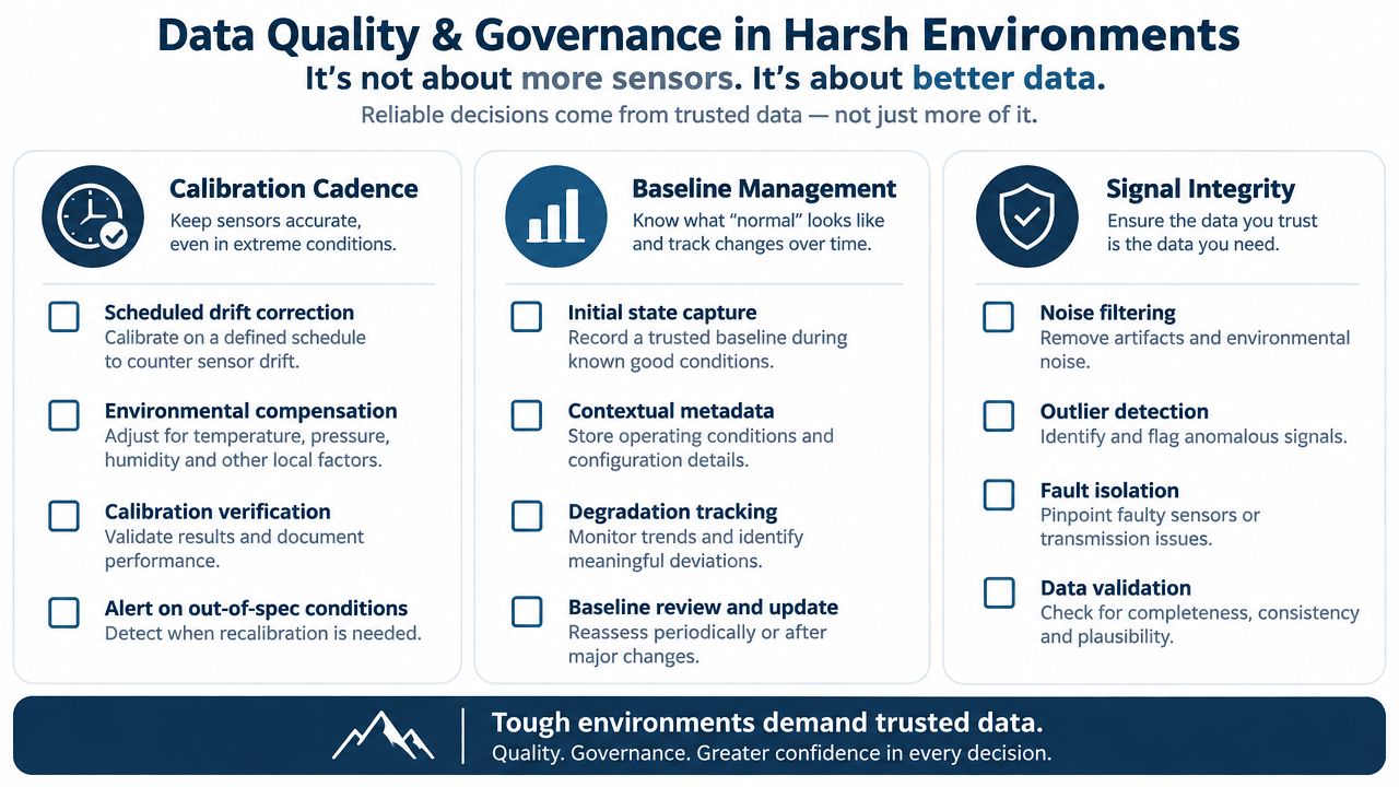
Capture a healthy operating window only after confirming that the asset is mechanically and electrically fit for service. Record operating state, speed, load, temperature, recent maintenance, and sensor identity. A baseline without operating context becomes a misleading reference.
For vibration, preserve the measurement settings and mounting arrangement. If the sensor moves from a bearing housing to a motor frame, the trend is no longer directly comparable. Exclude known noisy states, such as startup, shutdown, switching transitions, or unusual process conditions, unless the model is explicitly designed to analyze them.
Make calibration an operating process
MEMS accelerometers can drift. Piezoelectric sensors can show sensitivity changes with temperature and environment. Coating buildup, oil ingress, chemical attack, condensation, and loose mounting can all alter the signal before the monitored asset changes.
Use a governance routine that answers these questions:
- Who checks the sensor? Assign ownership to a named reliability or instrumentation role.
- What gets verified? Check sensitivity, channel continuity, timestamp quality, mounting condition, and environmental exposure.
- How is drift recorded? Keep calibration and replacement history with the asset and sensor identity.
- When is data excluded? Define rules for missing, saturated, duplicated, or obviously corrupted readings.
- What triggers replacement? Use condition, verification results, exposure history, and maintenance policy rather than waiting for total sensor failure.
A smaller, well-governed estate often delivers more dependable insight than a sprawling installation with uncertain calibration and inconsistent baselines. In steel, mining, chemical, and marine environments, sensor protection and data validation aren't administrative extras. They're part of the reliability design.
A Realistic Retrofit Path for Legacy VFDs and Critical Motors
Consider a 1990s-era 75 kW motor driving a critical fan through a legacy VFD. The plant has limited cabinet space, high electrical noise near the drive, and no appetite for a full controls replacement. The sensible retrofit isn't a large sensor network. It's a staged installation that proves the signal before expanding the scope.
Phase one targets the expensive failure modes
Start with a triaxial accelerometer on the drive-end bearing housing and a current transformer on the output feeder, provided the electrical design and measurement equipment are suitable for the VFD environment. The bearing location addresses a high-consequence mechanical failure, while current adds load and electrical context that vibration alone can't provide.
During commissioning, capture healthy data across the normal operating states. Confirm the mounting, cable route, grounding, timestamps, and operating context before setting alarms. The first return on the investment isn't a promised payback number. It's the ability to schedule an inspection or bearing change instead of discovering the defect after a trip.
Phase two fills the load-side gaps
Add an RTD or suitable temperature measurement at the motor winding or another engineered thermal point, then place vibration sensing on the driven fan or bearing location. This separates the drive-end story from the load-side story. It can also help distinguish a motor problem from a fan, coupling, or alignment problem.
Keep the electrical installation disciplined. Where high dV/dt and grounding challenges exist, use shielded twisted pair, secure the cable route, consider ferrite cores where appropriate, and establish the intended ground reference at the panel rather than casually bonding both ends. Confirm cabinet clearance and CT installation requirements before the outage window.
Phase three adds analytics after trust is earned
Only add edge analytics after the baseline alarms are stable and maintenance personnel know how to investigate them. The business case should be built from avoided emergency stops, reduced walk-around effort, better outage preparation, and deferred overhaul work. It should also include the cost of inspection, calibration, gateway maintenance, network integration, and technician training.
Market reporting illustrates why a focused retrofit is defensible. One predictive-maintenance market report valued the broader market at USD 14.2 billion in 2025 and projected USD 98.1 billion by 2033, with a 27.9% CAGR projection for 2026 to 2033. A separate industry source cited in the same reference material reported USD 17.11 billion in 2026 and a projection of USD 97.37 billion by 2034. The differing estimates reinforce that market size isn't a plant-level ROI calculation. Your justification must come from the consequence of failure and the quality of the intervention window.
Your Sensor Selection Checklist Before the Next Shutdown Window
Take this checklist into the planning meeting and require an answer for each block before anyone orders hardware.
Fault coverage
- Map failure modes: Identify the bearing, alignment, electrical, thermal, moisture, and contamination mechanisms that matter for the asset.
- Assign signals: Explain which modality detects each mode and which blind spots remain.
- Prioritize consequence: Start with assets where earlier warning can change the maintenance decision.
Mechanical installation
- Select the mount: Decide between stud, prepared epoxy, and temporary magnetic mounting based on access and required repeatability.
- Prepare the surface: Remove paint, rust, oil, and loose material where the measurement path requires a rigid interface.
- Route cables deliberately: Keep instrumentation wiring away from VFD output cables and protect it from heat, abrasion, and contamination.
Signal integrity
- Define bandwidth and sampling: Preserve the frequency content needed for the fault, and control aliasing.
- Confirm output compatibility: Match IEPE, voltage-mode, 4-20 mA, IO-Link, or another output to the acquisition system.
- Document grounding: Verify shielding, panel references, isolation, and continuity before accepting the data.
Architecture fit
- Choose the processing tier: Decide whether local edge features, on-premise integration, cloud analysis, or a hybrid approach fits the site.
- Connect the workflow: Show how an alert reaches the historian, CMMS, supervisor, and technician.
- Set governance: Define baseline capture, calibration checks, missing-data rules, and sensor replacement criteria.
Don't specify sensors before mapping failure modes. Don't under-budget mounting hardware, cable protection, commissioning, and calibration. Don't skip the healthy baseline during the shutdown window.
If the team can't justify at least two of these four blocks, defer the installation until the next outage. A delayed, engineered installation is safer than deploying predictive maintenance sensors that produce noise, false alarms, and no maintenance action.
DUCHENG Industrial supports VFD lifecycle work, including commissioning, troubleshooting, repair, preventive care, on-site reconditioning, and smart O&M or IoT consulting for industrial sites. Visit DUCHENG Industrial to discuss a sensor retrofit, monitoring architecture, or drive-maintenance plan built around your assets and operating conditions.