
Learn what a solid state contactor 3 phase is, how it differs from electromechanical units, key specs, and selection guidance for industrial applications.
A maintenance supervisor opens a heater panel after another set of mechanical contacts has worn or pitted. The load is familiar, the control circuit is straightforward, and replacing the contactor seems routine. But if the heater cycles frequently, repeated contact wear can turn a simple component change into a recurring maintenance job.
A solid state contactor 3 phase can remove physical contact wear and arcing during ordinary switching, but it isn't a drop-in answer for every circuit. Semiconductor devices produce heat, can fail short, and need protection and isolation designed into the installation. The practical decision is whether the load, panel, switching duty, and fault protection suit the device.
Table of Contents
- Why Three-Phase Solid-State Contactors Matter
- What a Solid State Contactor 3 Phase Is and How It Works
- Key Specifications for Three-Phase Solid-State Contactors
- Thermal Design and VFD-Driven System Considerations
- How to Select the Right Solid State Contactor
- Installation and Connection Best Practices
- Maintenance, Diagnostics, and Key Takeaways
Why Three-Phase Solid-State Contactors Matter
When a heater contactor fails repeatedly, the first question shouldn't be whether to replace it with the same type. Check what's driving the failures: frequent switching, contact damage, noise concerns, or the conditions inside the panel. A semiconductor contactor may address contact wear, but only if its thermal and protection requirements can be met.
A three-phase solid-state contactor switches AC power electronically, without moving contacts. That makes it useful where a process needs frequent switching and where contact noise or contact arcing is undesirable. It doesn't make the whole circuit maintenance-free, however. Heat must be managed, and the device doesn't replace the upstream means of isolation.
The distinction between application types matters. A heater bank has different switching demands from a motor, transformer, or VFD bypass circuit. A device selected by continuous current alone may still be unsuitable if the load has high starting current, frequent starts, or operating conditions that cause excessive temperature rise.
Practical rule: Treat the contactor as one part of the switching and protection system, not as a self-contained safety device.
A sound evaluation starts with the load and how it operates. Identify whether it's resistive or inductive, how often it switches, what control signal is available, and what the panel can dissipate. Then check the device's utilization category, current and voltage limits, ambient conditions, short-circuit coordination, and required isolation arrangement.
A solid-state contactor can be a good fit when frequent switching of industrial AC loads matches the contactor's thermal limits and application ratings for the installation. It can be a poor fit when an engineer assumes that silent switching means cool operation, assumes "off" means isolated, or applies a resistive-load rating to a motor duty. The right choice depends on the circuit's real operating conditions, not the technology label.
What a Solid State Contactor 3 Phase Is and How It Works
A solid-state contactor uses thyristors or triacs to conduct AC current on command. There are no moving contacts to burn, bounce, or wear. The trade-off is conduction loss: while the load is energized, the semiconductors generate heat continuously, so mounting and heatsinking are part of the working mechanism rather than accessories.
In a three-phase device, the controlled poles serve the line connections under a common control input. When the input is applied, the drive circuit gates the semiconductor switches. Current then flows for the portion of each AC half-cycle permitted by the device design. A thyristor pair or triac does not interrupt current like an opening mechanical contact. Conduction normally ends when load current crosses zero and the gate signal is absent. That behavior explains both the quiet operation and the need to consider leakage current, heat, and the actual electrical state downstream.
Many AC contactors use zero-cross turn-on. The control circuit waits until line voltage is near zero before gating the semiconductors, which reduces switching disturbance for resistive loads such as heater banks and avoids repeated energization at peak voltage. Zero-cross turn-on is not a universal suitability mark. An inductive motor load shifts current relative to voltage, while motor or VFD bypass duties can introduce starting and waveform conditions that the product must be rated and coordinated to handle.
Where IEC 60947-4-3 applies
Industrial non-motor semiconductor contactors sit within the IEC 60947 low-voltage switchgear framework, separately from IEC 62314 for all-or-nothing solid-state relays. IEC 60947-4-3:2020 covers semiconductor controllers and contactors for non-motor loads, including ON/OFF AC switching and voltage control in circuits up to 1,000 V AC, as set out in the IEC 60947-4-3 publication information. Its scope also permits multi-pole devices that switch the phases together.
For motor starting and soft-start duties, IEC 60947-4-2 covers semiconductor motor controllers, starters, and soft-starters. Check the applicable part together with the manufacturer's short-circuit protection arrangement. A compliant contactor still depends on the specified upstream protective device and circuit coordination.
| Attribute | Solid-state contactor | Electromechanical contactor |
|---|---|---|
| Switching action | Semiconductor conduction controlled electronically | Physical contacts open and close |
| Contact wear | No switching contacts to erode during normal operation | Contact surfaces can wear with repeated switching |
| Contact arcing | No mechanical contact arc during normal semiconductor switching | Opening and closing can produce arcing |
| Operating noise | Silent switching | Mechanical operation is audible |
| On-state loss | Semiconductor losses create continuous heat | Contact resistance losses are generally lower, depending on the device and duty |
| Off-state separation | Load remains connected through a non-conducting semiconductor path | Open contacts create a physical gap, subject to device design |
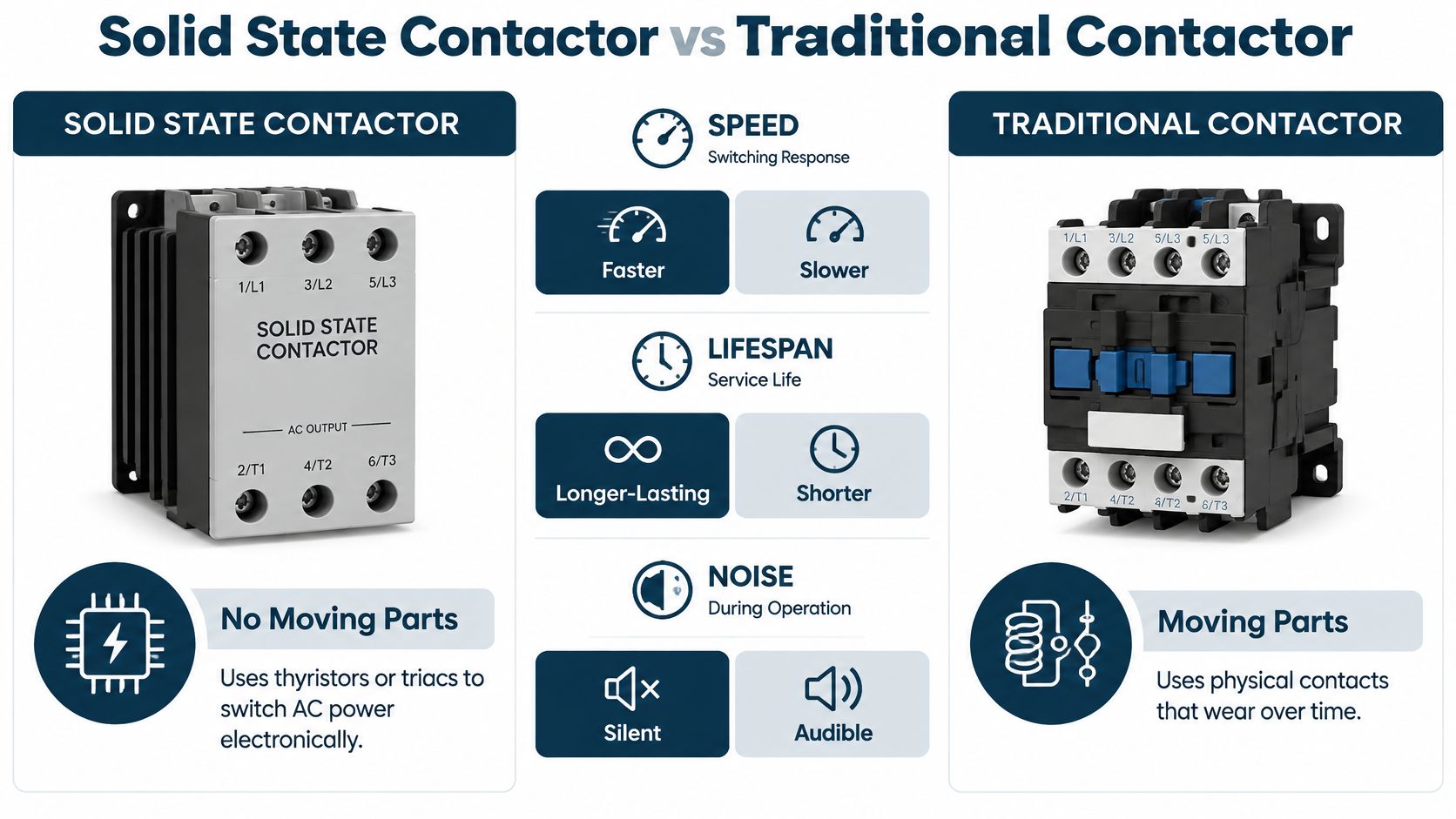
The comparison describes engineering trade-offs rather than a universal ranking. Solid-state switching suits repetitive AC load control where panel cooling and protection coordination are addressed. Electromechanical switching can be preferable where the application requires a physical contact gap or where continuous semiconductor losses are impractical. The deciding questions are how much heat the installation can reject, which protective device the manufacturer requires, and whether the actual duty is resistive, motor, or VFD-related.
Key Specifications for Three-Phase Solid-State Contactors
Start with the nameplate and the load, not the product title. A device may be described as three-phase, but its permissible load voltage, control input, current rating, and switching mode still have to match the installation. Also confirm whether the ratings apply to the same duty you intend to run.
Read ratings as a set
Commercial products show why a single current figure can mislead. One industrial three-pole family is specified at 25 A, for 24–520 V AC loads, with zero-cross switching and a 24–255 V AC/DC control input. A separate three-phase heater contactor is rated 45 A at 40 °C, for 100–240 V AC loads, with a 12–24 V DC control circuit. These are representative product figures, not universal limits; the three-phase contactor data sheet gives examples of how voltage, current, and control ratings vary by product.
| Parameter | Family A | Family B |
|---|---|---|
| Load current | 25 A | 45 A at 40 °C |
| Load voltage | 24–520 V AC | 100–240 V AC |
| Switching type | Zero-cross | Confirm the specific device data |
| Control input | 24–255 V AC/DC | 12–24 V DC |
The 45 A rating is tied to a stated ambient condition. It shouldn't be treated as the available current under every panel temperature, mounting arrangement, or duty cycle. Check the manufacturer's derating curve and installation requirements, then consider the actual cabinet environment and whether neighboring equipment adds heat.
Match the switching mode and wiring arrangement
Zero-cross operation is commonly suited to repeated switching of resistive heaters because it turns the load on near the AC voltage zero. A three-leg design can also support grounded-wye or star four-wire arrangements and open-delta six-wire configurations, where switching all three phases helps control neutral-connected or independently controlled loads. Verify the device's wiring diagram and application instructions before selecting the topology.
Control voltage is a separate question from load voltage. A correctly rated power device won't operate properly if the control input is incompatible with the PLC output or control circuit. Check the specified AC or DC control range, polarity where relevant, and expected signal behavior.
Finally, account for off-state leakage current. A semiconductor device may allow a small current to pass when commanded off, so a downstream circuit can retain a measurable voltage. Use a suitable isolation device for maintenance, and don't treat the semiconductor switching state as proof that the circuit is de-energized.
Thermal Design and VFD-Driven System Considerations
Heat is often the constraint that decides whether a solid-state contactor will work in a panel. Semiconductor conduction losses continue while the device carries current, even when the load is operating normally. A published power-contactor specification gives approximately 3.3 W/A of power dissipation and calls for current or duty-cycle reduction above 40 °C ambient. At 16 A, that relationship corresponds to approximately 52.8 W of heat before enclosure, mounting, and airflow effects are included, according to the power-contactor specification.
That heat has to go somewhere. Mount the contactor in the orientation specified by its manufacturer, allow the required clearance around the heat sink, and consider cabinet airflow rather than just room temperature. If the panel is crowded or poorly ventilated, a rating that looks adequate on paper may not be suitable at the actual operating temperature. Measure the cabinet hot spot under representative worst-case load and ambient conditions instead of assuming the enclosure stays cool.
Field check: If the device is warm at a modest load, inspect mounting, airflow, and duty before raising the current rating. A larger contactor may still overheat in the same restricted panel.
VFD bypass and motor duty
A VFD-adjacent contactor can face conditions very different from a heater switch. In a bypass circuit, the device may need to handle motor starting current and commutation transients. Don't select it solely by the motor's steady-state current or by a resistive-load rating.
Utilization categories show why the distinction matters. A representative contactor is rated 16 A for AC-51 resistive duty but 12 A for AC-53a motor duty, illustrating that the permitted current can change with the load category. The same specification reports approximately 3.3 W/A of dissipation and the need to derate above 40 °C, so thermal review and application review belong together.
For a VFD bypass or compressor circuit, verify the motor duty rating, starting conditions, protection coordination, and switching sequence against the manufacturer's instructions. Electronic switching doesn't provide galvanic isolation or guaranteed fault interruption. Include an appropriate upstream protective device, and make the thermal calculation part of the panel design rather than a commissioning afterthought.
How to Select the Right Solid State Contactor
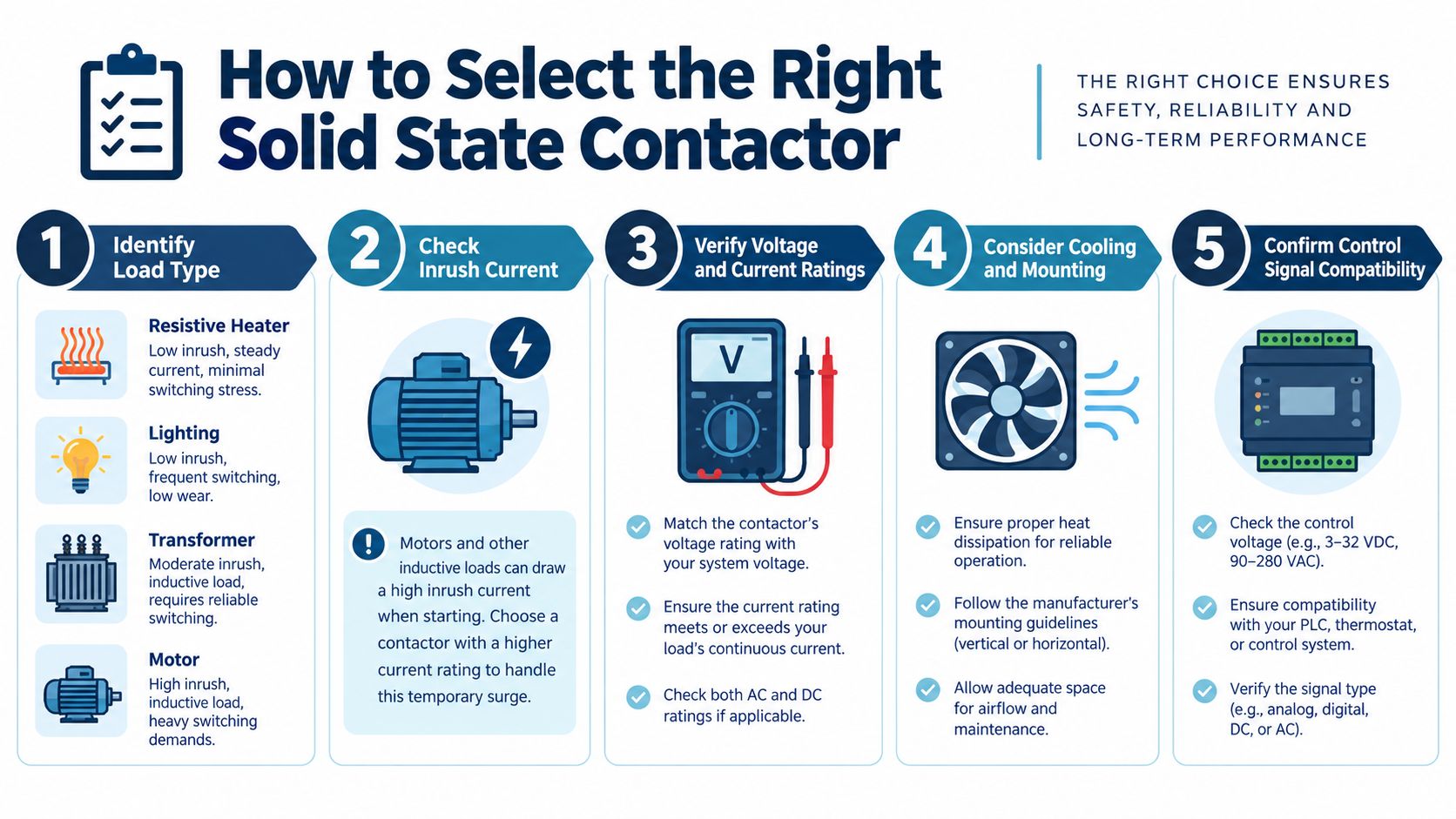
Selection should begin with the load's behavior, not a current-rating shortcut. A heater, lighting circuit, transformer, pump, and motor each impose different switching demands. Record the load type, supply voltage, operating current, control signal, switching frequency, and the environment where the contactor will be mounted.
A practical field workflow
- Identify the load. For resistive loads, confirm the steady current and switching pattern. For motors, compressors, pumps, and fans, include starting behavior and the manufacturer's required utilization category.
- Check starting current. A motor can draw 5–10 times its rated current during starting, and the inrush lasts longer than it does for a resistive load. Measure or obtain the starting current, then verify that it stays within the contactor's permitted inrush withstand level. The solid-state switching precautions emphasize checking motor inrush against the device's limits.
- Verify voltage and current. Match the load voltage, continuous current, control input, and operating frequency to the device data. Apply temperature and duty derating instead of relying on a headline rating.
- Coordinate short-circuit protection. Check the specified semiconductor fuse or protective-device requirements, including fuse I²t and breaker coordination. A contactor can be nominally rated for the load and still be damaged by a fault if the upstream protection isn't coordinated.
- Review the consequence of a fault. IEC coordination Type 1 permits permanent contactor damage after a short circuit. Type 2 requires the contactor to remain operational after the fault is cleared. Choose the level that fits the process and maintenance requirements, and include post-trip inspection in the response procedure.
For a motor, the selection record should include horsepower, locked-rotor current, starting frequency, thermal derating, fuse I²t, and the protective-device coordination basis. If an overload relay is part of the motor protection scheme, check how it coordinates with the contactor and the motor circuit. This thermal overload relay guide can help frame that protection review.
A load that keeps running after the control command is removed needs immediate attention. A failed semiconductor may short rather than open, so the control signal going low doesn't prove that the motor has stopped or that the power circuit is safe. Provide an independent isolation method and verify the circuit's state before maintenance.
Installation and Connection Best Practices
Mounting and wiring decisions have a direct effect on reliability. Follow the manufacturer's required orientation and clearance so the device can dissipate heat as designed. Keep neighboring components from obstructing airflow, and don't place the contactor where hot exhaust air from other equipment is drawn across its heat sink.
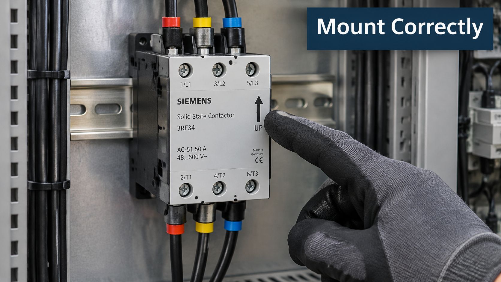
Before wiring, confirm the device terminals, control requirements, and phase arrangement against the manufacturer's diagram. A three-leg architecture may be used in grounded-wye or star four-wire and open-delta six-wire systems, but the suitability depends on the device design and load configuration. Check that all three phases are switched as intended, and verify the neutral or load connections rather than inferring them from the enclosure layout.
Treat isolation as a separate function
A solid-state contactor isn't a maintenance disconnect. Off-state leakage can leave measurable voltage downstream, and electronic switching doesn't provide galvanic isolation or guarantee that a fault will be interrupted. Install an appropriate upstream disconnect or circuit breaker with lockout/tagout capability, and verify absence of voltage before work begins.
A representative device rated at 500 V AC has an operating range of 48–575 V AC, a 40–100 Hz line-frequency range, a 1.2 kV peak off-state voltage, and maximum leakage current of 6 mA. Those values describe that particular device, not all contactors; the industrial AC contactor specifications illustrate why leakage and operating range should be checked in the product data.
Keep power conductors and low-voltage control wiring arranged according to the panel design, and maintain clear access to terminals and the isolating device. Protect the semiconductor contactor with a properly coordinated upstream fuse or protective device. For systems that also need phase-sequence or phase-loss supervision, review the function and placement of phase monitor relays as part of the wider motor-control design.
Use the video below as a visual reference, then verify each connection and protective measure against the specific device documentation and the site's electrical safety procedure.
<iframe width="100%" style="aspect-ratio: 16 / 9;" src="https://www.youtube.com/embed/RRFqYGINctA" frameborder="0" allow="autoplay; encrypted-media" allowfullscreen></iframe>Maintenance, Diagnostics, and Key Takeaways
No moving contacts means there's no contact surface to inspect for ordinary mechanical wear, but a solid-state contactor still needs planned checks. Semiconductor devices generate heat and depend on the panel's mounting and airflow. Inspect the heat sink for contamination, check that ventilation paths remain clear, and look for signs of overheating around the device and terminals.
Thermal monitoring is most useful when it reflects actual operating conditions. Check cabinet hot spots under the load and ambient conditions that challenge the installation, then compare results with the manufacturer's limits. During scheduled maintenance, verify terminal tightness according to the approved procedure, inspect control wiring and signal integrity, and confirm that protective devices haven't been bypassed or substituted without review.
A contactor that remains conductive after its command is removed may have a shorted semiconductor. Treat the load as energized until an independent disconnect is opened and the circuit is verified safe. After a trip, inspect the contactor and its upstream protection before returning the equipment to service. Don't assume that restoring the control signal or replacing a fuse has corrected the underlying fault.
The decisions that matter most are straightforward: match the contactor to the load, respect thermal derating, coordinate short-circuit protection, and provide independent isolation for maintenance. Those practices let solid-state switching serve reliably in process panels and VFD-centered systems without confusing reduced contact wear with reduced electrical risk.
DUCHENG Industrial provides multi-brand VFD commissioning, maintenance, troubleshooting, repair, and on-site reconditioning for industrial facilities across China and Southeast Asia. If your contactor application sits alongside a drive or VFD bypass system, visit DUCHENG Industrial to discuss support for the wider drive installation and its lifecycle needs.