
Learn what static frequency converters are, how they change frequency without moving parts, and where engineers use them in rail, marine and industry.
Three quotes land on your desk for the same job. One is a steel cabinet full of power electronics. One is a motor bolted to a generator on a skid. The third supplier sends back a question instead of a price, asking what the load does all day.
All three offers can be legitimate, and the gap between them is usually a gap in assumptions rather than in cost. The cabinet and the skid both change frequency. They age differently, they fail differently, and they ask different things of the grid they sit on.
If you already know motors and drives, most of what's inside a static frequency converter will look familiar: a rectifier, a DC link, an inverter, a control board. What changes is the job it's asked to do, and the ratings that decide whether it fits your site.
Table of Contents
- What a Static Frequency Converter Is and How It Differs
- How the Conversion Chain Works and What Wears Out
- Datasheet Ratings That Decide Whether an SFC Fits
- Where Static Frequency Converters Are Used Today
- Grid Coordination Checks Before You Specify One
- Buying a Serviceable SFC
What a Static Frequency Converter Is and How It Differs
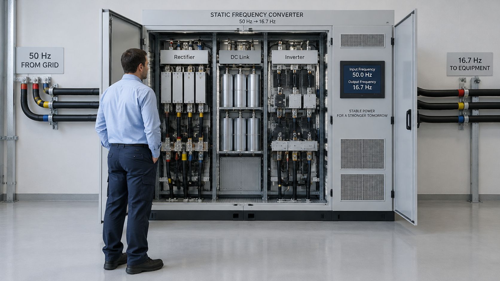
A static frequency converter takes AC power at one frequency and voltage and delivers AC at another, using semiconductors instead of a rotating machine. That's the whole proposition. The grid speaks 50 Hz or 60 Hz, the load speaks 16.7 Hz, 400 Hz or some adjustable value, and the converter sits between them and translates, the way an interpreter sits between two people who share no language.
Nothing in that translation depends on a shaft turning. "Static" means no moving parts in the power path, which removes bearings, couplings, brush gear and the alignment work that follows them. The electronics do the conversion, and the maintenance burden moves from mechanical checks to thermal and electrical ones.
Railway electrification shows why the mismatch matters. Sweden and Norway use single-phase 16.7 Hz traction power supplied from a three-phase, 50 Hz public grid, so the two networks can't be tied together. A Swedish technical study of static frequency converters describes the architecture as a rectifier that converts three-phase 50 Hz AC to DC, followed by an inverter that produces single-phase 16.7 Hz AC. The same study counts 58 converter units in Sweden, split into 16 cycloconverter units and 42 PWM-type units, a ratio that traces the move from early thyristor cycloconverters toward modern pulse-width-modulated designs.
That transition only became possible once the switching device existed. General Electric engineers invented the silicon-controlled rectifier, the thyristor, in 1957, and it made controllable rectifier and inverter stages practical without the shafts, generators and motors a rotary set requires.
A unit of this class reads as a switchgear lineup rather than a machine room:
| Architecture | Core Principle | Moving Parts | Typical Job | Main Maintenance Focus |
|---|---|---|---|---|
| Rotary frequency converter | Motor-generator set on a shared shaft | Yes, shaft, bearings and windings | Grid-to-grid frequency change, older rail links | Bearings, alignment, winding and rotor checks |
| Static frequency converter | Rectifier, DC link and inverter | No rotating parts | Rail traction, shore power, grid interties, frequency changes for MV equipment | Filters, DC-link capacitors, cooling, control boards and settings |
| Variable frequency drive (VFD) | Rectifier, DC link and inverter feeding a motor | No rotating parts | Speed control of an existing motor | Capacitors, cooling fans, filters and cabinet contamination |
The static converter and the VFD share an electronic chain, which is where most confusion starts. Ask two questions and the choice resolves itself. Does the source need to reach a load at a different frequency than the grid supplies? Then you're specifying a static frequency converter. Is the goal to vary the speed of an existing motor on an existing supply? Then you want a VFD, and the frequency conversion is a means rather than the purpose.
How the Conversion Chain Works and What Wears Out
Every unit runs the same five-stage chain, whether it's a wall-mounted cabinet or a railway installation the size of a substation. The stages don't change with size. The components, the currents and the thermal stresses do.
Here is the chain with the parts that age at the end of it:
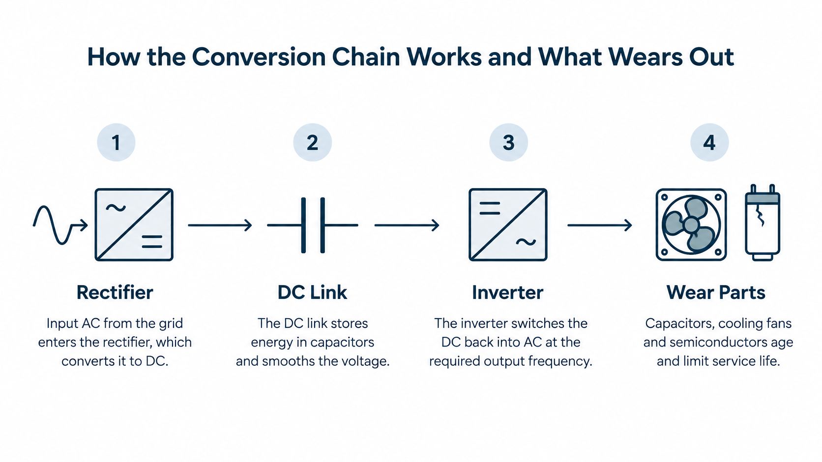
Stage by stage through the conversion chain
- Rectifier. Incoming AC is converted to DC. On a large unit this is a controlled bridge, and it sets two things at once: how much current the converter draws from the grid and how much distortion it sends back upstream. A rectifier section that's poorly filtered or running near its limit shows up first as heat in the cabinet.
- DC link. Capacitors store energy and smooth the DC voltage, so the output no longer depends on a spinning mass holding speed. The physical size of this stage decides how the converter behaves when a load steps: a motor start, a transformer energising, a nonlinear rectifier load switching in.
- Inverter. The inverter switches the DC rapidly, using pulse-width modulation in modern designs, to synthesize the required output frequency, voltage, phase arrangement and waveform. This is the stage that defines the output's character, and the stage where semiconductor losses concentrate.
- Filters. Switching produces harmonics, and the filter removes them before the output reaches the load. Filter reactors and capacitors carry continuous current, so a loose terminal or a sagging mounting bracket turns into local heating long before it turns into a fault code.
- Control loop. Sensors feed voltage and frequency back, and the loop corrects them within milliseconds as the load moves. The control board is also the component most exposed to heat, dust and firmware change, and the one whose drift is hardest to see without an event log.
The tank analogy: the grid is a pump arriving at a fixed rhythm, and the DC link is a tank that fills at that rhythm. The inverter is the sprinkler head drawing from the tank, so its rhythm is set independently of the pump. Change the pump's rhythm and the sprinkler still runs at the rate you chose, as long as the tank has volume to spare.
Where the performance numbers come from
Output quality is decided by the rectifier, the DC-link energy storage, the inverter modulation, the filtering and the control-loop response. It is not decided by inertia, because there is none. That's the trade: a static converter gives you millisecond control and an output isolated from input disturbances, and in exchange you inherit a set of components whose condition you have to track.
Newer architectures push the same idea further. Recent technical coverage points to modular multilevel converter designs in high-power traction, with reported power factor above 0.98 and roughly 70% lower harmonics injected into the catenary (technical coverage of converter architectures). Those numbers describe behaviour on the grid side. They say nothing about what the maintenance team faces on the panel side.
What wears out, and which check catches it
DC-link capacitors age first. Electrolyte dries, capacitance falls and equivalent series resistance climbs, which raises ripple and internal heating. A capacitor bank that's lost a third of its capacitance still runs the load, right up until the moment a start event pushes it over.
Cooling paths decide how long everything else lasts. Fans slow, heatsink fins pack with dust, filter mats clog, and the first symptom is derating or an over-temperature trip during the hottest week of the year rather than a clean failure.
Control boards and their settings drift. Parameters get edited during troubleshooting and never restored, event logs roll over, and the next fault takes longer to diagnose because the history is gone.
For global facilities the procurement risk sits here, not in the efficiency figure. A technically efficient converter is difficult to repair when firmware, gate-drive modules, sensors or subassemblies are proprietary or unavailable locally, and standardization, cybersecurity and workforce capability are still open questions around newer digital-control designs. Efficiency is the easy number to buy. Recoverability decides what happens in year eight.
A short walkthrough of the chain in motion, including how the DC link decouples input from output:
<iframe width="100%" style="aspect-ratio: 16 / 9;" src="https://www.youtube.com/embed/sQhll8CK33o" frameborder="0" allow="autoplay; encrypted-media" allowfullscreen></iframe>Here is how the failure points translate into planned work:
| Component | Check | Frequency |
|---|---|---|
| Cooling fans and heatsinks | Clean, test airflow and temperature rise | Each planned shutdown |
| DC-link capacitors | Visual check, capacitance and ESR test | Each shutdown or per manufacturer schedule |
| Filters and reactors | Inspect for heat discoloration and loose connections | Each planned shutdown |
| Control boards and firmware | Review event logs, back up parameters | Each shutdown and after every change |
| Cabinet environment | Check dust, humidity and contamination | Monthly walk-down |
| Spare modules | Confirm availability and compatibility | Before every planned shutdown |
The monthly walk-down is the one most sites drop first and regret later. A thermal image of the cabinet under load takes minutes and finds loose joints, hot reactors and tired capacitors before they take the process down.
Datasheet Ratings That Decide Whether an SFC Fits
Ratings decide fit. Efficiency decides nothing until the fit is right. A commercial high-power reference specification gives you a compact checklist to work through, and each row asks a question about your site rather than about the converter.
| Parameter | Reference Value | What It Means in Practice |
|---|---|---|
| Rated capacity | 125 to 2,000 kVA | Sets the size range for the load |
| Input power factor | Unity | Little reactive power drawn from the grid |
| Input current distortion (THDi) | Below 3% at rated load | Holds under IEEE 519 only when Isc/IL is below 20 |
| Output voltage distortion (THDv) | Below 2.5% with linear loads | Verify separately for nonlinear loads |
| Voltage accuracy | Plus or minus 1% | Stable supply for sensitive equipment |
| Frequency accuracy | Plus or minus 0.1% | Matches target frequency for motors and rail systems |
| Overload capability | 120% for 10 minutes; 150% for 30 seconds | Covers motor starts and load peaks |
| Short-circuit current | 200% for 2 seconds | Limits the fault current the converter contributes |
Reading each row against your own site
Capacity frames the class of equipment. Below the range you're into a different product family, and above it you're into a project rather than a product.
Unity input power factor matters when your supply is already loaded or when reactive power is billed, because the converter draws almost no reactive current.
The THDi figure carries a condition. That below-3% claim is stated at rated load and only holds under IEEE 519 when the short-circuit ratio (Isc/IL) is below 20. At a weak point of connection the ratio runs higher, so verify distortion at your actual ratio and load mix rather than accepting the headline.
The THDv figure carries a condition too. Below 2.5% applies with linear loads, and a rectifier-fed DC load on the same bus is not a linear load. Ask for the number at your load mix.
Voltage and frequency accuracy are the rows that decide whether sensitive equipment sees a clean supply. Plus or minus 1% on voltage and 0.1% on frequency is tighter than most grids deliver, which is the point.
Overload and short-circuit current are the sizing rows. The 120% for 10 minutes and 150% for 30 seconds windows tell you how much starting surge the unit absorbs, while the 200% for 2 seconds ceiling tells your protection engineer how much fault current the converter can push into a fault.
Size the load before you read the table
Add the motor starting kVA, the nonlinear rectifier load and the transformer inrush to your steady load, then compare the total against the overload windows. Doing it in that order stops the common mistake of matching a converter to a steady-state nameplate while the actual duty is a 150% surge twice an hour. For motor-side selection rather than source-side conversion, the variable frequency drive unit guide walks through the drive sizing path.
Four questions to send the supplier with your enquiry:
- What short-circuit ratio applies at our point of connection? The THDi claim depends on it.
- How was the THDv figure measured, and with what load mix?
- What start duty must the converter ride through, and how often?
- How long do our overload events last compared with those windows?
Where Static Frequency Converters Are Used Today
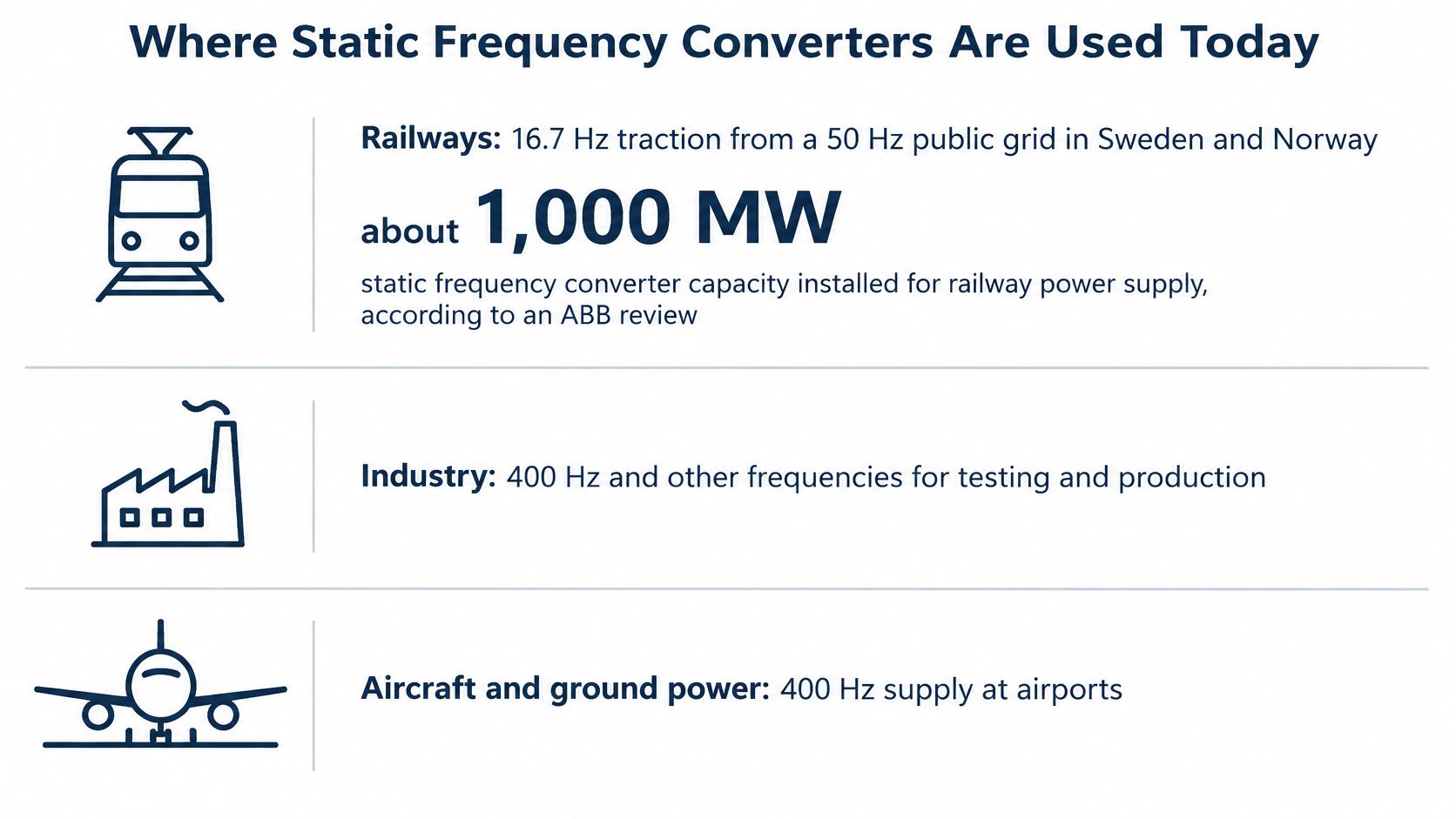
Railways put the clearest number on the technology's scale. Traditional systems used rotary machines to exchange power between single-phase railway grids and three-phase national grids, and power-electronic converters progressively replaced them. A review of railway power conversion published by ABB reports that static frequency converters with an aggregate capacity of approximately 1,000 MW were commissioned in the 15 years before its 2010 publication.
The same record shows how concentrated that build was: about two-thirds of the capacity, roughly 667 MW, came from one supplier, and more than 800 MW of further capacity was under construction or on order at the time. Two modern 25 MVA railway frequency converters commissioned in Giubiasco, Switzerland, in 1994 set an individual project scale of 50 MVA.
Railway units also do more than shift frequency. They can decouple grid and catenary frequency and phase, which lets an operator manage constrained grid capacity and avoid building a dedicated high-voltage connection for a single traction section.
Five other places the same architecture earns its place
Shore power at berth. A vessel built for one frequency sits at a port running another. The converter has to hold frequency accuracy while a ship's load swings hard as auxiliary systems start and stop, and it has to do it without tripping on the inrush.
Aircraft ground power. Airborne equipment runs on 400 Hz because higher frequency makes transformers and motors lighter. A parked aircraft on maintenance needs that supply from the ground, and the converter carries the load of avionics checks, cabin systems and test rigs.
Shipboard frequency adaptation. Equipment ordered for one regional standard frequently ends up installed in another. Converting at the distribution level is often cheaper than replacing the equipment, provided the converter tolerates the nonlinear load of modern shipboard electronics.
Medium-voltage industrial supply. Plants running MV equipment built for a foreign standard use frequency conversion rather than a wholesale replacement programme. Here the converter is judged on harmonic injection at the point of common coupling, because the MV bus feeds everything else.
Test benches and fixed-frequency processes. An export machine has to be tested at the destination frequency before it ships, and some processes need a fixed frequency regardless of what the local grid delivers. Ride-through during the test cycle matters as much as accuracy on the rating plate.
The pattern connecting all of them is simple. The converter earns its place when the source and the load are both fixed and different. The moment either side becomes adjustable by design, you're usually describing a drive rather than a converter.
Grid Coordination Checks Before You Specify One
A higher-rated converter is not automatically a more resilient one. That's the assumption worth challenging before the purchase order, because a bigger unit with poorly coordinated controls can undermine the very grid stability it was bought to improve.
A modern static frequency converter can act as a controllable intertie between sources and loads operating at different frequency and voltage levels, while also supporting interoperability, ancillary services and optimized energy transfer (Hitachi review of power system technology). That description is broader than "frequency changer", and it changes how the equipment should be compared.
The decision that comes before the datasheet
The question is whether the converter should be selected alone or coordinated with STATCOMs, synchronous condensers, battery systems and grid-forming converters. Low-inertia grids increasingly need fast active and reactive power support during disturbances, and power-electronic systems can respond on millisecond timescales. Whether that speed helps depends on control coordination and on which network weakness is being addressed.
Compare a converter against a transformer-plus-converter arrangement by system role, not by megawatts, input and output frequency, or efficiency alone. Two sites with identical loads can need different answers because one has a strong short-circuit level and the other is at the end of a weak feeder.
The studies to request before you sign
- Short-circuit strength. What does the converter contribute to fault level, and does the existing switchgear still rate correctly with it in service?
- Harmonic interaction. Model impedance at your actual short-circuit ratio rather than the datasheet's assumed one. If the plant already runs drives, the harmonic filter guidance for VFD installations covers the resonance checks that apply just as well to a converter on the same bus.
- Transient stability. How do the converter controls behave through a voltage dip, a source loss and a reclosing event?
- Protection coordination. Converter fault current is limited, so protection settings written for a transformer-fed bus may no longer grade correctly.
- Control-mode compatibility. Does the converter follow the grid or form it, and does that mode match the other assets on the bus?
- Islanding and ride-through behaviour. Decide in advance whether the converter should ride through a disturbance, trip, or support an islanded section, and confirm that operations agree with the answer.
The question to answer first: which specific network weakness is this converter meant to fix? Capacity, harmonics, phase decoupling and inertia support lead to different specifications, and a unit sized for one rarely performs best on another.
Poorly coordinated controls don't announce themselves at commissioning. They show up months later as unexplained trips, oscillating power flows or protection operations that nobody can reproduce on demand.
Buying a Serviceable SFC
The question isn't whether the converter is efficient. It's whether anyone can repair it in year eight, in your building, with the parts that are obtainable.
Confirm serviceability first. Give the supplier or service provider the brand, model and voltage class and get an explicit answer on whether that specific combination is supported locally. A generic "we service all brands" is not an answer.
Ask about spares and firmware access. Gate-drive modules, sensors, control boards and subassemblies all need to be sourceable, and firmware access decides whether a replacement board can be commissioned or only swapped and hoped for.
Decide where repair happens. Complex component-level faults on transportable units usually go to the workshop, while large MV and HV systems and planned maintenance are handled on site. We plan every job on that basis, because transport risk and downtime cost differ enormously between the two paths.
Set the maintenance interval against your shutdown calendar. If the site only stops twice a year, the capacitor and cooling checks have to fit those windows, and the spare-module position gets confirmed before each one rather than during it.
The open questions worth asking about aging assets
For newer modular architectures, four practical questions still separate a confident supplier from a vague one:
Ask before you sign: how many submodules can fail before the unit derates, how is capacitor-voltage imbalance diagnosed, do bypassed modules create hidden thermal stress, and how does a technician validate a safe restart after a control or cooling fault?
Weigh efficiency and harmonic performance alongside recoverability, obsolescence exposure, remote diagnostics, cybersecurity boundaries, environmental derating and technician competency. A converter that needs a factory visit to clear a control fault is a different asset from one the site team can bring back inside a shift.
When you hand the job to a service provider, send the nameplate data, the short-circuit ratio at the point of connection, the load duty including start events, and the recent event logs. That package shortens diagnosis more than any site visit description, and it's the difference between a targeted repair and a process of elimination.
When a converter trips and the line stops, the recovery depends on having a service team that already knows the equipment class, the settings and the spare-module position. DUCHENG Industrial supports industrial facilities across China and Southeast Asia with multi-brand VFD and converter commissioning, preventive maintenance, on-site reconditioning and workshop-level component repair, backed by 14 service locations and a Thailand subsidiary in Rayong. Send us the nameplate details and event logs through DUCHENG Industrial and we'll tell you what the fault path looks like before anyone opens the cabinet.