
Learn what a tandem GFCI breaker is, how it differs from standard breakers, and which panel compatibility and safety checks to make first.
Can a tandem breaker give you ground-fault protection when your panel has no spare spaces? Sometimes. The question that decides it isn't the one most buyers ask. They ask whether the breaker fits, and the answer is usually yes. The critical question is whether the panel's label lists that exact position for that exact device, and whether the two circuits leaving it are two separate 120-volt loads.
Get either part wrong and the compact device stops being a shortcut. It becomes a code violation, a nuisance trip that maintenance resets every week, or in the worst case a shared-neutral circuit that heats a conductor nobody is watching.
Table of Contents
- Tandem GFCI Breakers Compared With Standard Breakers
- How a GFCI Breaker Detects Ground Faults
- Where a Tandem GFCI Breaker Falls Short
- Where a Tandem GFCI Breaker Makes Sense
- Panel Listing Checks Before You Install
- Testing and Troubleshooting Repeated GFCI Trips
Tandem GFCI Breakers Compared With Standard Breakers
Short answer first. A tandem GFCI breaker puts two independent 120-volt single-pole circuits and ground-fault protection into one panel space, and it's permitted only in a panel and a bus position listed for that device.
Most confusion starts because several different products get called the same thing on a shelf or in a catalog photo. The table below lines up the five devices people ask about.
| Breaker type | Circuits per space | Ground-fault (GFCI) protection | Panel requirement |
|---|---|---|---|
| Standard single-pole breaker | 1 circuit (120 V) | No | Any open single-pole space |
| Standard tandem breaker | 2 independent 120 V single-pole circuits | No | Listed tandem positions only |
| Single-pole GFCI breaker | 1 circuit (120 V) | Yes, typically trips near 4–6 mA for personnel protection | Any open single-pole space |
| Tandem GFCI breaker | 2 circuits (120 V), each with ground-fault sensing | Yes, on both circuits | Listed panel and listed tandem position only |
| Standard two-pole breaker | 1 circuit (240 V) with common disconnect | No | Standard two-pole space |
Read it in two passes. First find the row that matches what you want the circuit to do. Then read the last column before you read the price.
Two rows get misread constantly. A standard tandem and a tandem GFCI look nearly identical in a photo, and the standard one gives you two circuits with no ground-fault protection at all. Put it on a wet-area receptacle circuit and you've kept the shock risk you were trying to remove. The other confusing pair is the single-pole GFCI and the tandem GFCI. Both protect people. Only the tandem doubles the circuit count, and manufacturer and panel documentation for these compact devices describes them in exactly those terms: two 1-pole, 120-volt circuits occupying one breaker space.
The two-pole row ends most bad plans. A two-pole breaker feeds one 240-volt circuit and opens both legs together, which is what a dryer, a range, or a shared-neutral branch needs. A tandem can't do that job however the terminals are landed. Devices that combine arc-fault and ground-fault sensing are a different family again, covered in this overview of the dual-function breaker.
How a GFCI Breaker Detects Ground Faults
How can a breaker tell when current has found an unintended route? A garden hose offers a simple analogy. Water flows out and returns; if some escapes along the way, the amount coming back is smaller. A GFCI breaker checks for the electrical equivalent of that leak.
Current leaves on the hot conductor and should return on the neutral. A sensing coil inside the breaker compares the outgoing and returning current. When they match, the breaker stays closed.
If current returns by another path, such as through a person, water, damaged insulation touching conduit, or a contaminated terminal block, the two amounts differ. The sensor detects that difference and trips the breaker. The diagram shows how the two flows are compared.
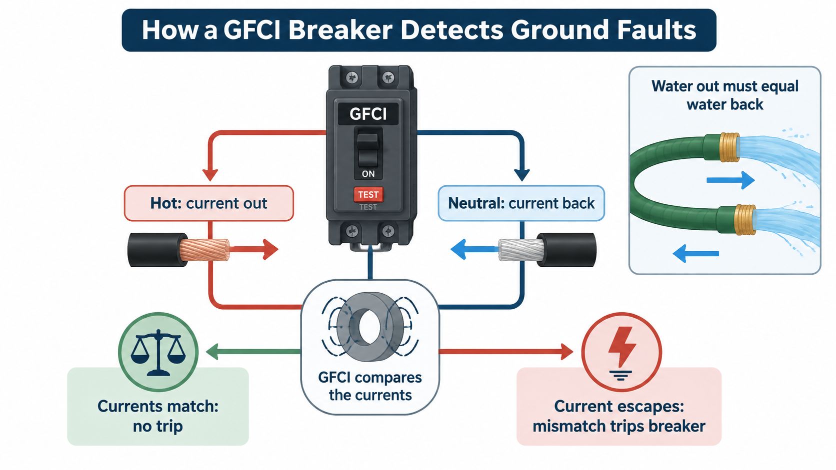
Two jobs inside one case
A GFCI breaker contains two separate protective mechanisms. The thermal-magnetic element responds to sustained overloads and high-current short circuits. The differential sensing element responds to leakage current.
Each mechanism answers a different question. The first responds to excessive current that can heat conductors; the second detects current escaping its intended path. A circuit can have a functioning GFCI element and still have an undersized conductor, because the differential sensor does not assess conductor size.
Why the sensitivity is set so low
A low trip threshold helps a GFCI respond to potentially dangerous leakage. A U.S. Consumer Product Safety Commission analysis reported an average of 196 residential consumer-product electrocutions per year during the five-year period beginning in 1995. It also cited a 1999 study estimating that 47%, about 92 deaths annually, could have been addressed by extending GFCI protection to more residential circuits. The CPSC analysis of GFCI protection also cited an earlier Underwriters Laboratories study estimating GFCIs were 81% to 95% effective in preventing electrocution deaths, corresponding to an estimated 75 to 88 preventable deaths per year.
What changes on a tandem
A tandem GFCI has a separate sensing path for each of its two circuits. Each path must be wired correctly for its circuit to receive protection. If a conductor is misrouted, that side may lose its protection even though the breaker still appears and feels normal.
This is why a tandem GFCI is a panel-listing and circuit-topology choice, not a way to save space. The breaker's sensing can protect each circuit only when the installation matches the panel's listed configuration and the conductors are routed correctly.
Where a Tandem GFCI Breaker Falls Short
The mistake that causes the most trouble is treating a tandem GFCI as a compact two-pole breaker and assigning it a 240-volt load. It is two single-pole devices sharing a slot. Both circuits sit on the same bus leg, so the pair normally cannot supply a 240-volt load or provide the common disconnect a multi-wire branch circuit needs, as this analysis of tandem breaker limits and installation sets out.
The shared neutral trap
A multi-wire branch circuit is two hot conductors sharing one neutral. Older commercial and industrial spaces use this layout often. The two breakers sit side by side, so the pair looks like two unrelated circuits.
The shared neutral works like a return lane sized for leftover traffic, not for both lanes at full load. On opposite bus legs, the two hot currents cancel in that neutral, so it carries only the difference. A tandem puts both hots on the same leg. The currents then add. The neutral carries the sum and heats as if both loads were stacked on one return wire.
Independent tandem handles do not repair that current path. Two separate toggles also do not guarantee that both ungrounded conductors open together when someone works on the circuit.
Fixing a shared-neutral circuit with a two-pole breaker
A two-pole breaker, or a listed handle tie where the code allows it, opens both hots together and keeps the two legs opposite. Ground-fault sensing does not do that job. The GFCI element may trip on leakage from a shared-neutral circuit, and it still will not give simultaneous disconnect or correct neutral current behavior.
A GFCI answers one question only: did current leave the circuit by a path it shouldn't have? Sizing a conductor, protecting a neutral, and opening both legs together are separate jobs with separate devices.
Before you buy the device, trace which conductors share a neutral, what the neutral current becomes when both hots sit on one leg, and whether anything opens both hots at once. Those answers decide the topology. Counting free slots does not.
Where a Tandem GFCI Breaker Makes Sense
A tandem GFCI earns its slot when two things are true at once. You need ground-fault protection on two separate 120-volt loads, and the panel position is listed for a tandem device. When both hold, the density gain is real and the protection is genuine.
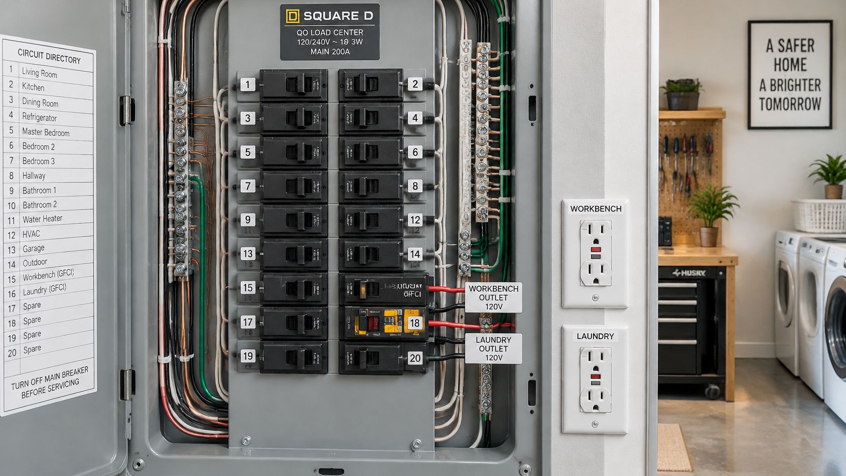
Three layouts show the pattern. A control room panel that's nearly full still needs ground-fault protection on two receptacle circuits feeding bench outlets and a cleaning station. One listed tandem position covers both, and no panel expansion is required. A utility building with an outdoor receptacle pair needs personnel protection at both points, and the second circuit counts only if it's a second 120-volt load rather than half of a 240-volt feed. A workshop or auxiliary cabinet on an industrial site is usually short on spaces rather than short on amperage, which is precisely when density becomes the reason to look at this device instead of a subpanel.
What holds in all three cases is the limit list. The label must allow a tandem in that position. Both current-carrying conductors of each protected circuit must pass through the sensing system. The load can't be a 240-volt appliance or a shared-neutral multi-wire branch circuit.
Here's a short walkthrough of the device in a real panel, so the physical layout is clear before you open yours.
<iframe width="100%" style="aspect-ratio: 16 / 9;" src="https://www.youtube.com/embed/K6JP5E0hPZA" frameborder="0" allow="autoplay; encrypted-media" allowfullscreen></iframe>When a limit fails, the honest options are a subpanel, a new circuit pulled to a different space, or a two-pole breaker for the 240-volt or shared-neutral load. Forcing a tandem into an unlisted bus position trades a little money now for an inspection finding and an unpredictable device later.
Panel Listing Checks Before You Install
Which listing, on which bus stab, decides whether this breaker may stay? The click of the jaws only shows that the metal lined up. The panel listing shows the manufacturer tested that breaker family in that position.
A panel works like a keyed lock. Two keys can look alike and still fit the wrong door. Sitting flush behind the deadfront is the same kind of clue: useful, and incomplete on its own.
Do the checks in the table before money changes hands. Each row is a separate gate.
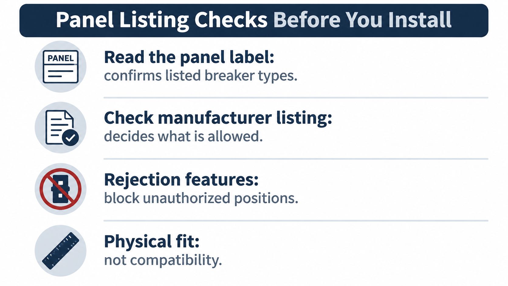
Run the sequence in order and stop at the first failed check. Skipping a failed row is how an unlisted device ends up feeding a circuit for years.
| Check | Where to find it | Pass condition |
|---|---|---|
| Panel listing | Panel label and manufacturer directory | Tandem GFCI named for this panel family |
| Bus position marking | Label inside the panel door | Position marked for tandem breakers |
| Breaker family | Breaker part number and panel compatibility list | Exact series matches the panel |
| Interrupting rating | Breaker label compared with available fault current | Rating equals or exceeds available fault current |
| Neutral arrangement | Panel wiring and breaker neutral pigtail | Neutral connected as the panel system specifies |
| Certification marking | Breaker label | Marked as GFCI to UL 943, Class A for grounded-neutral systems |
Why mixed-brand panels fail the check
A breaker from one maker rarely carries a listing for a panel from another, even when the bus teeth match and the device seats cleanly. Some panels add rejection features, small tabs that block a device from a position the maker never tested.
The panel label governs which device types are permitted and how many overcurrent devices the panel may hold, as this review of NEC tandem breaker rules explains. Names and certification systems differ by market, so generic "universal tandem" advice travels badly across borders.
Practical rule: if you can't find the panel family and the position on the manufacturer's own compatibility list, treat the answer as no.
Where the neutral has to land
The opening comparison already set this device as two independent 120 V positions in one space. What changes the protection, once the listing is settled, is the neutral landing.
On a circuit that has a neutral, the load neutral ends on the breaker's dedicated neutral terminal. The white pigtail, or the plug-on-neutral clip, then lands where that panel system specifies. Those two landings are not interchangeable between panel designs.
A neutral that returns on the panel bar outside the sensor, or that bonds downstream to an equipment grounding conductor, leaves the sensor comparing unequal paths. The result is nuisance trips, or a reading that never sees the fault. Class A personnel protection is commonly specified at roughly 4 to 6 mA of ground-fault current, and the device must include a manual supervisory test, per the UL 943 standard for Class A GFCIs.
If the panel listing is the limit, start with how many spaces and how much current the enclosure can accept. This guide to breaker box capacity and selection walks through that choice before another breaker goes on the bus.
Testing and Troubleshooting Repeated GFCI Trips
Press the test button and confirm the device trips. It takes seconds, and it belongs in the maintenance log next to the date and the initials.
Skipping it isn't a theoretical risk. A survey recorded by the U.S. Consumer Product Safety Commission found approximately 15% of tested circuit-breaker GFCIs were non-operational, compared with 8% of receptacle GFCIs, according to this breaker product documentation. A device that fails can leave power available while offering no protection at all.
VFD-fed circuits need their own thinking. Input filters, cable capacitance, motor insulation degradation, contamination, and switching-related leakage all produce high-frequency residual current that can look like a fault. Technical guidance on GFCI breakers with VFD loads notes that wiring errors, neutral-to-ground faults, and insulation failures still cause trips even with higher-frequency-compatible designs, and calls for verifying line and load wiring, neutral routing, and the single neutral-ground bonding point.
Before energizing, confirm the interrupting rating against the panel's available fault current, verify the exact panel and position compatibility, torque terminals to the manufacturer's specification, run the built-in test, and record leakage-current measurements under normal operating conditions. That baseline is what makes a later trip interpretable. On our side, the Rapid Restore on-site fault response starts with alarm and event-log context before anyone touches a reset, which is the same discipline a repeating GFCI trip deserves.
| Symptom | Likely cause | Corrective action |
|---|---|---|
| Trips immediately on reset | Wiring error, neutral-to-ground fault or insulation failure | Check line and load wiring and neutral routing before any further reset |
| Trips only under load | Equipment leakage or moisture in the cable | Measure leakage under normal operation and inspect cable and equipment |
| Trips on a VFD-fed circuit | High-frequency residual current from filters or cable capacitance | Confirm a higher-frequency-compatible GFCI design and review wiring |
| Test button does not trip the breaker | Failed GFCI device | Replace the breaker and inspect the circuit |
| Trips with no load connected | Downstream neutral-to-ground bond or shared neutral | Check neutral arrangement and the single bonding point |
| Trips after wet weather | Moisture ingress in an outdoor circuit | Dry the circuit, inspect insulation, then restore power |
Repeated trips are a diagnostic signal, not an invitation to keep resetting. Investigate, correct the cause, then restore power once.
Plant maintenance teams bring us drive problems that look like breaker problems: nuisance trips, residual current on VFD-fed circuits, faults that clear on reset and return a week later. DUCHENG Industrial provides multi-brand commissioning, maintenance, troubleshooting, repair, and on-site reconditioning for low-, medium-, and high-voltage drives across China and Southeast Asia, and our engineers work from fault records and documented diagnostics rather than repeated resets. If a compact breaker configuration keeps tripping on a drive circuit, send the nameplate photo, the fault display before any reset, and one wider shot of the installation, and visit DUCHENG Industrial to start the request.