
Learn how a variable speed drive air compressor is sized, tuned, and commissioned, with realistic savings and trip diagnostics for plant teams.
The U.S. Department of Energy estimates that 30% to 50% of compressed-air power can be lost during operation. That makes a variable speed drive air compressor more than an equipment upgrade: it's a way to manage how a compressor responds to changing demand. But the drive only helps when its control range fits the plant's real load profile.
A correctly selected and commissioned VSD can cut waste during partial-load operation. An oversized unit, a poorly coordinated compressor room, or a machine that spends too much time below its effective turndown can erase that advantage. The practical test is not whether the motor speed changes. It's whether the system delivers stable pressure with less power per volume of useful air.
Table of Contents
- Why Plants Move to a Variable Speed Drive Air Compressor
- How to Size for Turndown and Choose the Right Role
- Control Strategies That Hold Header Pressure
- Tuning Pressure and Measuring Real Energy Savings
- Commissioning Checks Before You Hand the System Over
- Fault Diagnostics and the Practical Next Step
Why Plants Move to a Variable Speed Drive Air Compressor
A 100-horsepower constant-speed rotary-screw compressor draws about 25% of full-load power while unloaded, while the VSD-controlled compressor in the same operating example uses 0% while unloaded (technical analysis of compressed-air system performance). That difference can matter when plant demand shifts with production schedules, batch cycles, and changing use across a shared header.
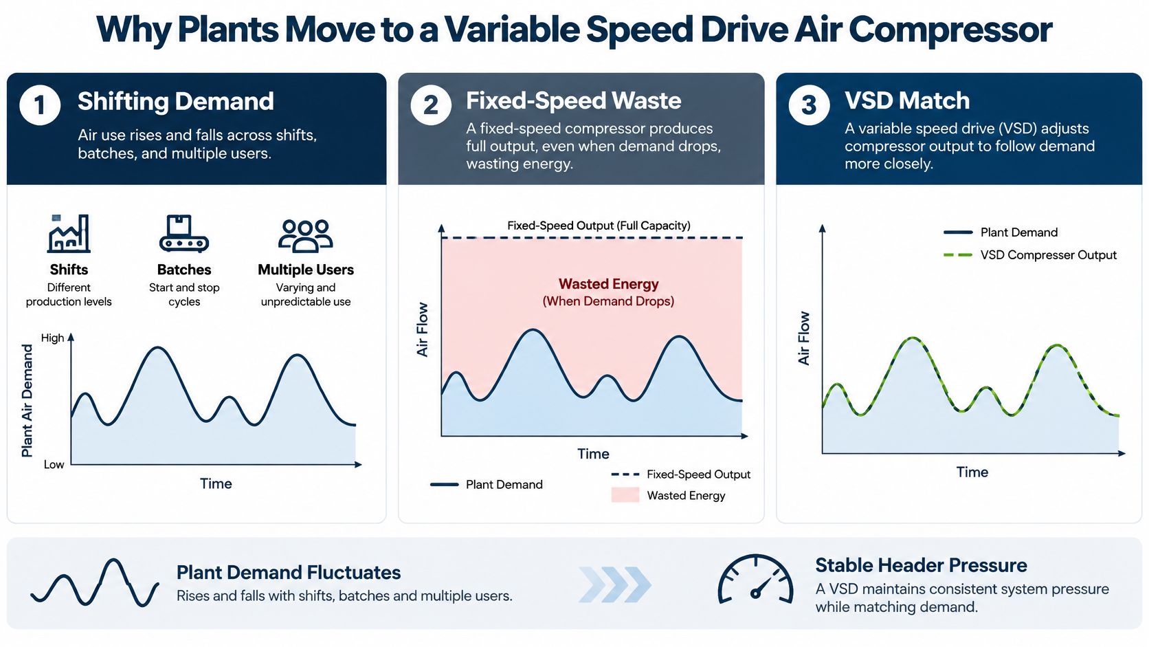
A fixed-speed compressor typically responds through load/unload cycles. It produces air at a set motor speed while loaded, then unloads once pressure reaches its upper limit. During unloading, the motor may still draw substantial power without producing useful air. A variable speed drive adjusts motor speed to bring airflow closer to current demand, reducing the time spent at full output when the plant needs less air.
Consider a mixed-use plant with several production lines on one shift and mostly support equipment on another. A batch process may create a brief peak, while shared tools add smaller, less predictable draws through the day. Speed control can help the compressor follow these changes, although the benefit depends on how the machine is set up and how other compressors respond.
Control strategy matters more than the nameplate
The Department of Energy estimate of 30% to 50% potential power losses makes system control a significant part of compressed-air efficiency, as the same analysis notes. The same analysis reports possible annual energy savings of 15% to 50% from broader system optimization, depending on leakage, pressure, sequencing, demand variation, and equipment condition. Treat those savings as the ceiling of an optimization program, not a result a new inverter delivers on its own.
That distinction should shape the purchase decision. Motor horsepower gives the compressor's rated capacity, but it does not show how often the plant needs that capacity or whether the selected machine can operate efficiently at actual demand. A drive can reduce off-load losses and unnecessary cycling. A control range that does not fit plant demand, or poor sequencing with other machines, can erode that gain.
Plant rule: Start with measured demand, not the motor rating. A VSD is an energy-management tool, and its value depends on how the whole compressed-air system is operated.
How to Size for Turndown and Choose the Right Role
Sizing starts with a demand profile. Log compressor flow, or infer demand from operating data, alongside electrical power, header pressure, compressor run and load status, and production state. Include representative shifts, weekends, startups, and abnormal peaks. Then compare minimum, average, peak, and shift-change demand with the proposed machine's actual turndown curve.
A VSD cannot necessarily control usefully from maximum flow down to zero. Oil-flooded machines typically turn down to about 70% of peak flow, and most VSD compressors reach a maximum turndown of 65% to 80% of rated flow (VSD selection and application guidance). Use the lower figure when the plant's minimum demand is close to the machine's limit. Below its practical operating range, a compressor may unload or stop. If demand regularly falls into that region, the control arrangement needs another way to handle the gap.
Compare roles against the measured range
| Role | Demand pattern that fits | Efficiency note | Main risk |
|---|---|---|---|
| VSD as the only compressor | Demand varies across the day, and the VSD's operating range covers normal low-to-high demand | Speed can follow changing load without relying on a fixed-speed baseload unit | The compressor may spend too much time unloading if demand drops below its effective range |
| VSD as the trim machine | Fixed-speed equipment can carry stable base demand while one VSD handles normal variation | A VSD can trim fluctuating demand while fixed-speed units remain suited to steady operation | A mismatch between base-load capacity and VSD range can create a control gap |
| Smaller fixed-speed unit paired for stable base load | A consistent low-level requirement can be separated from variable or peak demand | Fixed-speed equipment can be more efficient at full load | Poor sequencing or a poorly chosen unit size can lead to cycling and pressure swings |
In a multi-compressor room, each base-load unit's capacity should fit within the VSD's control range. Otherwise, the VSD may reach minimum output as a fixed-speed unit unloads or cycles. An oversized VSD can spend too much time unloading. An undersized one may leave fixed-speed equipment handling fluctuations it cannot manage smoothly.
Choose the machine by its role and flow range, because horsepower on the nameplate says nothing about how often the plant needs that capacity. Check the proposed unit's operating limits against measured demand, then verify its behavior after startup. Compare flow, power, pressure, and load status across actual production conditions before judging whether the selected arrangement is working as intended.
Control Strategies That Hold Header Pressure
Once the compressor roles are clear, the next task is deciding how the machines share load. Set a target header pressure that meets actual end-use needs, then define a narrow, practical control band around it. The VSD should handle routine fluctuations within its usable range, while fixed-speed equipment supports relatively stable base demand or covers peaks.
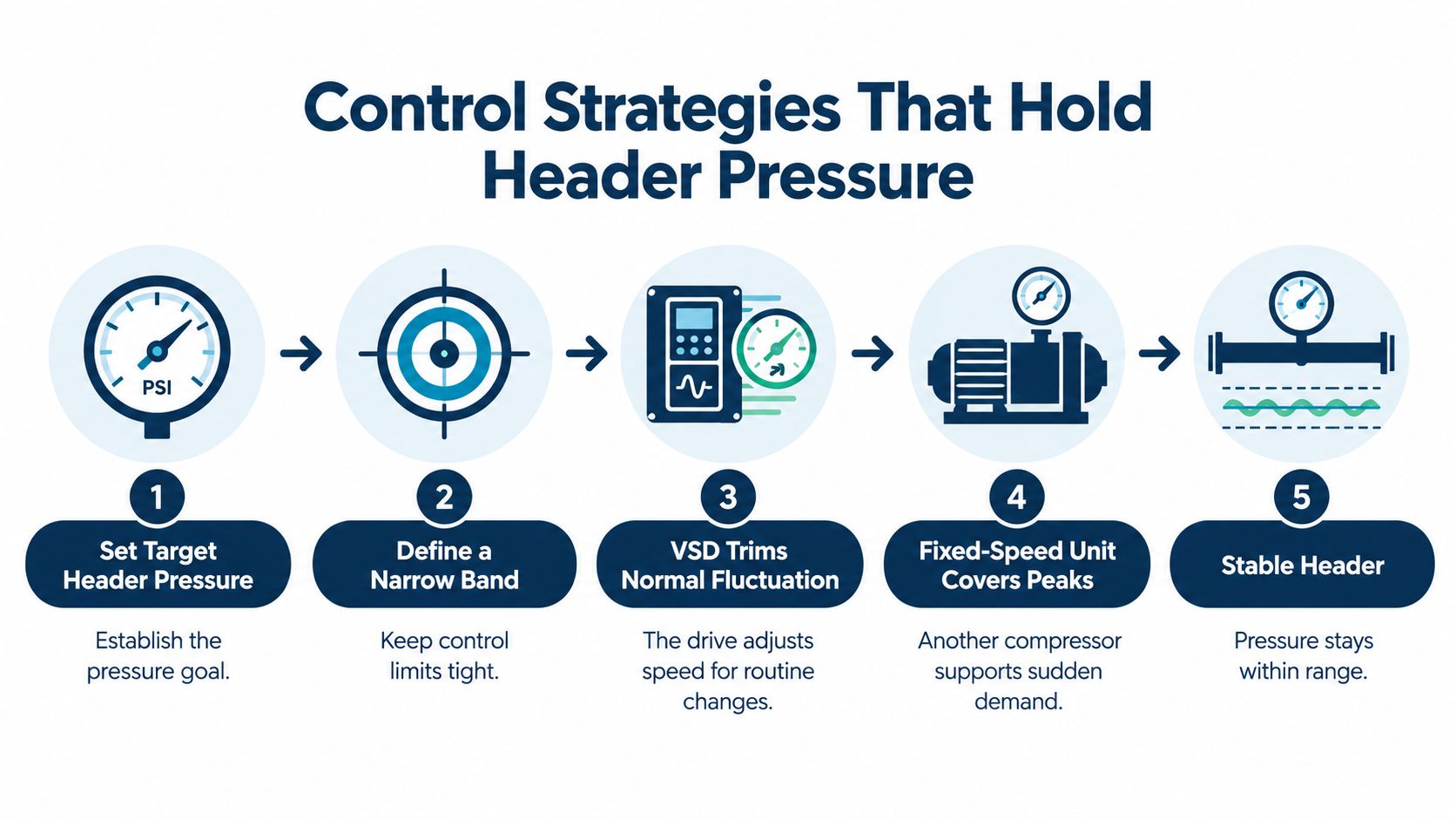
A control gap shows up in the pressure trend and in compressor behavior. The VSD is already at minimum output, yet demand falls further. A fixed-speed unit then unloads or cycles, the header pressure swings, and pressure-sensitive production equipment may be disturbed. That isn't a reason to raise the setpoint automatically. It's a reason to review the load-sharing arrangement and the limits of the machines in the room.
Verify the signals and sequence
Check pressure-transducer wiring and scaling against the controller's displayed pressure and an independent reading. Confirm minimum-speed behavior, acceleration and deceleration ramps, start permissives, and the interaction between the compressor controls and the emergency stop. If multiple compressors use independent pressure controls, they may compete for the same load rather than following one coordinated sequence. The result can be unnecessary starts, unstable pressure, or a drive responding to the actions of another machine.
Keep the control scheme observable. Trend header pressure alongside each compressor's run/load status and the VSD's speed reference or feedback. When pressure moves, those traces help show whether the cause is an incorrect signal, a sequencing problem, a control gap, or a genuine change in demand. For related examples of drive control approaches, see DUCHENG Industrial's overview of VFD control methods.
Include electrical conditions in the control review
A VSD adds a rectifier and inverter to an existing electrical network. Where the site has sensitive automation, other drives, long motor-cable runs, or a weak supply, establish a baseline power-quality picture and measure harmonics under representative operating conditions. Check grounding, shielding, and motor-cable condition as part of the assessment.
DC chokes, active-front-end designs, and external filtering are options to evaluate on larger or sensitive installations, not automatic add-ons. The right choice depends on what the site measurements show. A compressor that holds pressure but causes nuisance trips or interference elsewhere hasn't delivered a sound control solution.
Use the following video as a visual reference for the pressure-control approach:
<iframe width="100%" style="aspect-ratio: 16 / 9;" src="https://www.youtube.com/embed/dFTeI07J9hM" frameborder="0" allow="autoplay; encrypted-media" allowfullscreen></iframe>Tuning Pressure and Measuring Real Energy Savings
A properly sized VSD compressor can save up to roughly 35% versus a comparable fixed-speed unit. Examples for suitable applications put compressed-air cost reductions at about one-third (CAGI's variable-speed drive technical brief). A documented replacement case reports annual savings of $33,019 after installing a correctly sized VSD compressor, assuming stable operating conditions. These figures are benchmarks for assessing an opportunity, not a promise for a specific plant.
Actual results depend on how the compressor operates. Drive losses may add roughly 3% to 5% relative to a fixed-speed compressor, and a VSD that runs persistently near or below its effective turndown range may lose its advantage (VSD commissioning and system-control guidance). Leaks, poor sequencing, and an unnecessarily high pressure band can also reduce expected savings.
Pressure management can provide a separate improvement. CAGI's pressure guidance notes that reducing system pressure by 2 psi can reduce power consumption by approximately 1%; a 12-psi reduction could represent more than 6% power savings if the lower pressure still meets end-use requirements. Confirm that the most demanding legitimate user receives the required pressure at the point of use before lowering the system setpoint.
Pressure tip: Keep the band only as high as the highest legitimate user requires. If one process needs more pressure than the rest, assess that demand directly rather than raising the whole system for every user.
To verify savings, compare before-and-after trends under comparable production conditions. Review loaded and unloaded hours, electrical kilowatts, specific power, starts per hour, and header-pressure stability. Accept the result only when pressure is stable and kilowatts per delivered volume of air have fallen. Lower motor speed by itself does not meet that test.
Plant rule: Keep the savings claim tied to measured operating conditions.
Compare two comparable weeks of trends and calculate kilowatts divided by cubic metres of delivered air for each. If production, demand, or operating hours changed, record the difference rather than presenting the comparison as like-for-like. A defensible result identifies what changed, what remained comparable, and whether the improvement persisted after commissioning.
Commissioning Checks Before You Hand the System Over
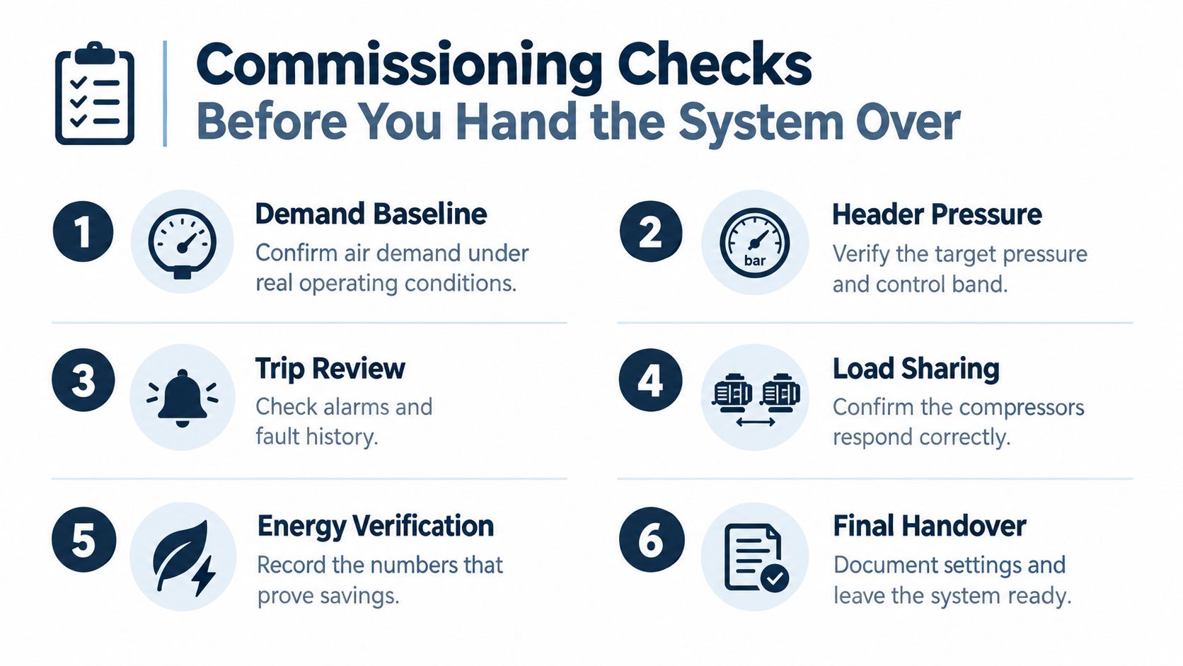
Commissioning should turn the demand profile into a verified operating sequence, not just confirm that the compressor starts. First confirm that the VSD's minimum-to-maximum flow range covers normal fluctuations, and check that each base-load unit's capacity fits inside that range. Include low-demand operation in the test, because screw compressors may modulate efficiently only above roughly 50% of design capacity (VSD operating and maintenance guidance).
Commission across the real demand envelope
Verify the pressure-transducer wiring and scaling, then confirm the target pressure and control band. Test the ramp rates and minimum-speed behavior. Check emergency-stop interaction and restart permissives before handing the system to production. Run the compressors at representative loads, including a low-demand period, rather than approving the system after a convenient near-full-load test.
A useful handover includes before-and-after trends for pressure stability, loaded and unloaded hours, kilowatts, specific power, and starts per hour. Compare the records under representative operating conditions so the team can distinguish a genuine efficiency improvement from a change in production or demand.
For a commissioning record format and related checks, use DUCHENG Industrial's VFD commissioning checklist.
Reject a pass based on a single run
Nameplate-based sizing can miss the plant's actual low-demand periods. Skipping weekends, shift changes, or startup behavior leaves gaps in the evidence. A pressure band set unnecessarily high can also make the compressor appear stable while wasting energy. In a multi-compressor room, independent controls can interfere with one another even when each machine passes an isolated test.
Record the operating settings and the conditions under which the system was tested. If pressure remains stable but cycling is frequent, investigate the control gap or sequence before sign-off. If cycling is minimized but kilowatts per delivered volume haven't improved, review pressure, leakage, loading behavior, and the validity of the comparison.
Sign off only when the system meets the plant's pressure requirements, minimizes unnecessary cycling, and improves kilowatts per delivered volume. That gives operations and maintenance a baseline for future fault diagnosis and performance checks.
Fault Diagnostics and the Practical Next Step
When a variable speed drive (VSD) compressor trips, preserve the evidence before resetting it. Record the trip code and freeze-frame values, including DC-bus voltage, output current, heatsink temperature, speed reference and feedback, discharge pressure, oil temperature, and recent load/unload transitions. Without this record, the conditions that triggered the fault may be lost.
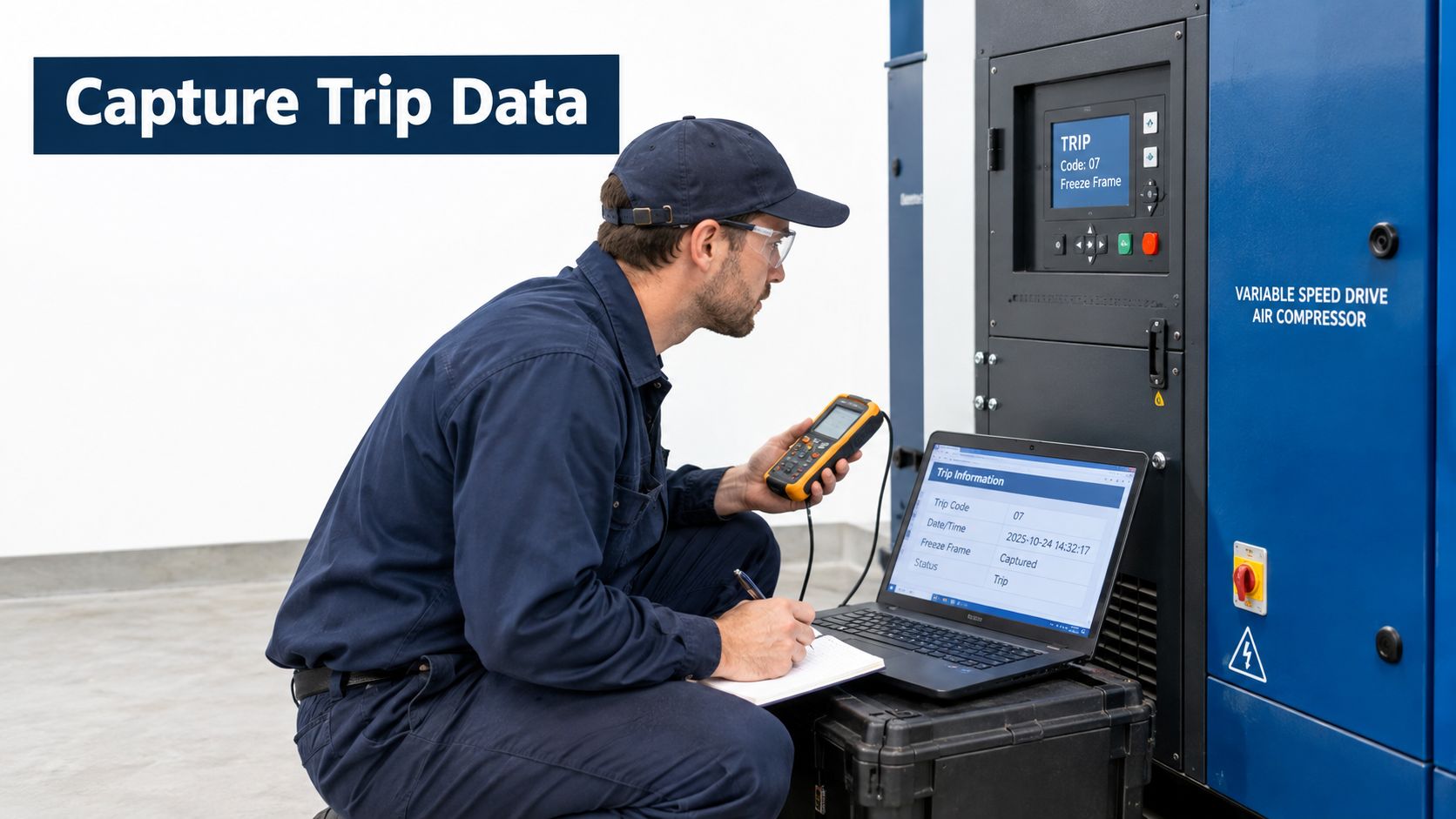
Trace the fault before attempting recovery
Make the equipment safe before opening a cabinet or testing conductors. Inspect for contamination, blocked cooling paths, failed fans or filters, loose terminals, grounding issues, motor-insulation concerns, encoder or speed-sensor wiring faults, and pressure or temperature transmitter problems. After inspection, conduct controlled insulation, phase-balance, and functional tests.
Dust, conductive carbon contamination, salt, restricted cooling, loose terminations, and thermal cycling can contribute to drive faults. Repeated overcurrent trips, unexplained pressure oscillation, rising cabinet temperature, or frequent load/unload cycling warrant root-cause investigation. A restart may restore operation temporarily while the original fault remains.
During functional testing, verify acceleration and deceleration ramps, minimum-speed behavior, pressure control, emergency-stop interaction, restart permissives, and operation at representative loads. Test across the plant's demand range and record trip frequency, recurring alarms, temperature margin, vibration, pressure deviation, specific energy, and mean time between failures (MTBF). These measures help confirm whether the initiating condition has been removed.
Choose a controlled recovery
A drive trip can involve the compressor, motor, sensors, air header, and control sequence as well as the drive itself. Reliable recovery depends on tracing the evidence, correcting the cause, and confirming repeatable operation before returning the asset to service.
For an active trip or a planned shutdown involving a multi-brand drive, a 24-hour emergency line is available in China and Thailand, and a service record can be opened through the customer portal. Its Nanjing and Hangzhou headquarters and Rayong subsidiary provide regional context for that service. Prioritise a documented diagnosis and a controlled restart before any further reset.
DUCHENG Industrial provides multi-brand VFD commissioning, preventive maintenance, troubleshooting, repair, and on-site reconditioning for drive systems supporting variable-speed compressors. For an installation, shutdown, or recovery after a trip, contact DUCHENG Industrial to discuss the drive checks and service support your plant needs.