
Learn what a variable speed motor is, how VFDs control speed and torque, and what to check before installing one in an industrial drive system.
A motor is running, but the process rarely needs its full output. The operator closes a valve, adjusts a damper, or changes a mechanical transmission, while the motor continues consuming power as though maximum flow were required. That arrangement may keep production moving, but it can also hide wasted energy and create unnecessary mechanical stress.
An industrial variable speed motor system addresses the problem differently. A variable frequency drive, or VFD, changes the electrical frequency and voltage supplied to the motor, allowing the shaft speed and torque to follow the process demand. The idea sounds simple, but the installation isn't a motor with a larger control knob. Harmonics, cable length, insulation stress, bearing currents, load type, and retrofit compatibility all influence whether the system performs reliably.
Table of Contents
- What a Variable Speed Motor Actually Does in Industry
- How Variable Speed Motor Control Evolved
- How a VFD Controls Speed and Torque
- Energy Savings and Where They Actually Apply
- Hidden Side Effects in Real Industrial Installations
- How to Select a Variable Speed Motor for Your Drive System
- Comparing Motor Types Used with Variable Speed Drives
- A Lifecycle View of Variable Speed Motor Decisions
What a Variable Speed Motor Actually Does in Industry
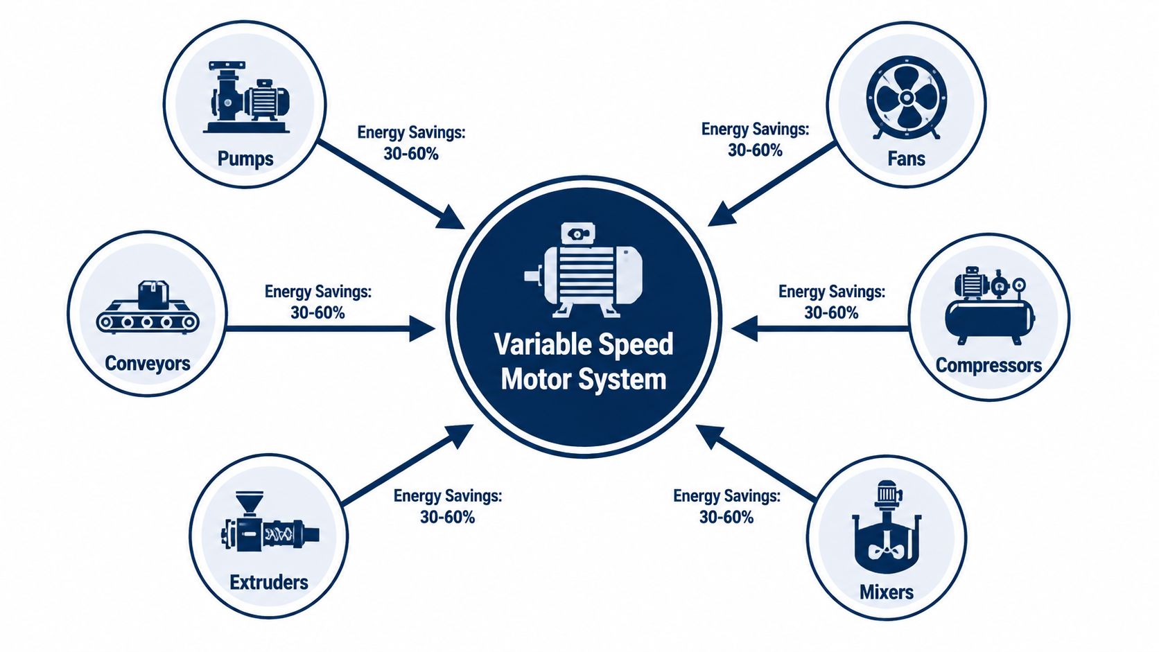
Most industrial equipment doesn't need to run at full speed continuously. A pump may need less flow during part of a production cycle. A fan may only need reduced airflow after the process reaches temperature. A conveyor may require controlled acceleration, while an extruder or mixer may need steady torque across a changing load.
A variable speed motor is best understood as part of a system, not as an isolated motor. The system normally includes the motor, VFD, control signals, protective devices, cables, coupling or gearbox, and driven equipment. The VFD receives a speed or process command, converts incoming AC power, and produces an output whose frequency and voltage suit the required operating point.
That differs from a consumer product labeled “variable speed.” A drill trigger, for example, may change speed through a simple user command. An industrial drive must coordinate speed, torque, acceleration, current, thermal limits, fault handling, and process feedback while operating for long periods in a demanding environment.
The practical operating sequence
A plant team can build the right mental model by following the power path:
- The process creates a demand. A controller, operator, sensor, or PLC requests a particular flow, pressure, speed, or production rate.
- The VFD interprets that command. It adjusts output frequency and voltage rather than forcing the motor to remain at one fixed electrical speed.
- The motor converts electrical input into controlled shaft motion. The coupling, gearbox, belt, or direct connection transfers that motion to the load.
- The load determines the result. A centrifugal fan responds differently from a conveyor because each load requires a different torque profile.
This distinction matters during design. A VFD can reduce throttling losses in a variable-torque application, but it can't make every load behave like a fan. For constant-torque equipment, the drive still has to provide substantial torque at reduced speed.
How Variable Speed Motor Control Evolved
Modern VFD systems emerged through several waves of power-electronics and control development. Practical industrial use of AC variable speed drive technology began in the late 1950s, with heavier industrial adoption following in the 1970s. Later milestones included the first microprocessor-controlled industrial VFD in 1982, an IGBT-based drive line in 1988, and ABB's Direct Torque Control in 1995, as documented in this history of AC drives and industrial variable speed control.
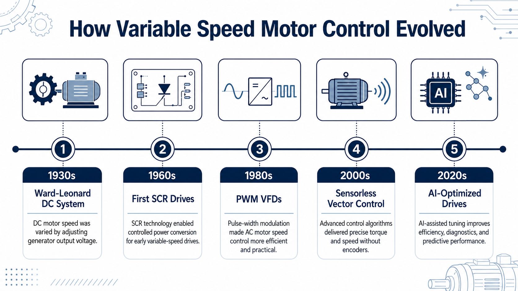
Earlier systems established the basic possibility of adjustable speed but brought serious trade-offs. Ward-Leonard arrangements offered smooth DC motor control through a motor-generator set, yet they required substantial equipment and maintenance. DC drives later improved with semiconductor rectifiers and SCR technology, but brushes and commutators remained part of the motor system.
AC VFDs changed the maintenance model. They removed the commutator from the common induction motor arrangement and used semiconductor switching to synthesize a variable-frequency supply. That improvement introduced a new engineering concern, the non-sinusoidal waveform and its effects on motor insulation, bearings, electromagnetic compatibility, and power quality.
Why modern features exist
The evolution explains why a contemporary drive package often includes more than a motor and inverter. Inverter-duty winding systems address repeated voltage stress. Shaft grounding measures help manage bearing-current paths. Line reactors and output filters address power-quality and motor-terminal concerns. Vector control and sensorless algorithms improve torque response where basic volts-per-hertz control isn't enough.
The important lesson is historical. Variable speed control didn't become reliable because one component solved everything. It became practical as semiconductors, microprocessors, switching methods, motor construction, and control algorithms matured together.
A plant team evaluating a retrofit should therefore treat the VFD as an engineered electrical system. The motor's original fixed-speed operating conditions may not have exposed the insulation, bearing, cable, and harmonic issues that appear after the change.
The following video provides additional visual context on the operating principle of variable speed drive systems.
<iframe width="100%" style="aspect-ratio: 16 / 9;" src="https://www.youtube.com/embed/JGSA9ghEjM0" frameborder="0" allow="autoplay; encrypted-media" allowfullscreen></iframe>How a VFD Controls Speed and Torque
A VFD controls motor speed primarily by changing the frequency applied to the stator. For an AC machine, synchronous speed follows the relationship:
n = 120f / p
Here, n is synchronous speed, f is electrical frequency, and p is the number of poles. An induction motor runs slightly below synchronous speed because it needs slip to produce torque. When the drive lowers frequency, the motor's operating speed also falls, provided the applied voltage and load remain within the system's limits.
Below base speed, the drive commonly maintains an approximate volts-per-hertz relationship. That keeps the motor's magnetic flux in a usable range. Above base speed, the drive enters a field-weakening region. The motor can rotate faster, but available torque reduces as the system approaches its electrical and thermal limits.
What the load does with that command
Fans and centrifugal pumps are the classic variable-torque loads. Their torque demand typically rises with the square of speed, while power rises with the cube of speed. The Energy Institute guidance reports that a 20% reduction in fan speed can cut power use by about 50% in suitable variable-load systems, and Natural Resources Canada's VFD guidance explains why drives are especially effective when equipment spends meaningful time below full speed.
A conveyor behaves differently. Reducing speed doesn't automatically remove the force required to move the belt and product. The drive may still need to deliver near-constant torque, so current, motor cooling, acceleration time, and overload capability become more important than the cube-law energy effect.
For a fuller treatment of drive architecture and operating principles, see this variable speed drive overview.
VFD speed and torque regions
| Speed Region | Control Mode | Torque Behavior | Power Behavior |
|---|---|---|---|
| Below base speed | Approximate volts-per-hertz or vector control | Torque depends on load type and current limit | Variable-torque loads can reduce power sharply |
| Around base speed | Rated-frequency operation | Rated torque is available within thermal limits | Power rises with process demand |
| Above base speed | Field weakening | Available torque declines | Speed can increase while power remains constrained |
| Very low speed | Vector control may be required for demanding loads | Cooling and low-speed torque need verification | Efficiency and thermal performance require attention |
The drive's frequency command is only the starting point. The motor, load curve, cooling method, and control mode determine whether that command becomes stable production or repeated overcurrent and overtemperature faults.
Energy Savings and Where They Actually Apply
The strongest energy case appears when a motor drives a variable-torque load, especially a centrifugal pump or fan. In these applications, flow changes roughly with speed, pressure changes with the square of speed, and power changes with the cube of speed. A modest speed reduction can therefore remove much more power demand than a simple reduction in output might suggest.
Industry guidance cited by the Energy Institute places typical VSD energy savings at 15% to 40% in variable-load systems, while its example of a 20% fan-speed reduction indicates about 50% lower power use. Schneider Electric guidance also identifies reductions of up to 50% as realistic for centrifugal loads. These are application-dependent figures, not a promise for every motor or operating profile. They depend on the load curve, control strategy, operating hours, and time spent at partial demand.
A fixed-speed pump controlled by a partly closed valve still runs the motor near its fixed operating point. The valve converts excess pressure into a process restriction. A VFD instead reduces motor speed so the pump produces closer to the required flow and pressure.
Load type determines the business case
| Load category | Typical examples | Where speed control helps | Main limitation |
|---|---|---|---|
| Variable torque | Centrifugal pumps and fans | Large energy reduction at reduced speed | Savings fall when operation stays near full speed |
| Constant torque | Conveyors, mixers, extruders | Process control, soft starting, and some optimization | Torque and current remain significant at low speed |
| High-inertia or demanding duty | Hoists, winders, selected compressors | Controlled acceleration and dynamic response | Requires careful overload and braking assessment |
Research reviews summarized by the Energy Institute report 5% to 15% typical energy-use reductions across industrial motor applications, with some studies finding 20% to 65% depending on the load and control strategy. Those ranges reinforce the central decision rule: don't estimate savings from motor horsepower alone.
Build the retrofit calculation around the load
Before approving a retrofit, collect the operating profile:
- Operating hours: Record how long the equipment runs and whether it operates continuously or in cycles.
- Speed distribution: Identify the time spent at full, medium, and low speed.
- Control method: Compare throttling, bypass operation, mechanical transmission losses, and direct speed control.
- Electrical cost: Use the site's actual kWh cost rather than a generic assumption.
- Process constraints: Confirm minimum flow, minimum speed, cooling requirements, and product-quality limits.
A constant-torque conveyor may gain more from controlled acceleration and improved process matching than from dramatic electrical savings. A fan that frequently runs below design demand is a different investment case entirely.
Hidden Side Effects in Real Industrial Installations
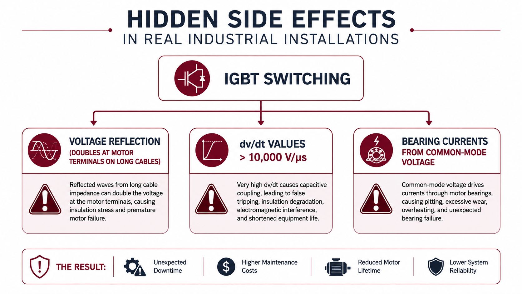
A VFD can improve control while creating electrical conditions that a fixed-frequency motor never experienced. The switching waveform contains harmonic components and fast voltage transitions. These effects can increase motor temperature, noise, vibration, and loss, particularly when the motor, cable, and drive weren't selected as one system.
PWM switching creates additional motor losses, including iron losses and rotor eddy-current losses. The technical discussion of harmonic-related motor losses under variable-frequency supply notes that IEC 60034-2-32 addresses test methods for these losses and cites adjustments of about 10% to total motor losses for machines above 150 kW under certain variable-frequency conditions.
The installation constraints
Harmonics can propagate from the drive into the plant electrical system. They may affect power quality, heating, or sensitive equipment. Natural Resources Canada notes that VFDs generate harmonic voltages and currents and identifies line reactors and filters among possible mitigation measures.
Insulation stress comes from rapid voltage changes and reflected-wave behavior, especially where the cable run and motor-terminal conditions create unfavorable peaks. An inverter-duty motor with an appropriate winding system provides a stronger starting point than an older general-purpose motor.
Bearing currents can arise from common-mode voltage and high-frequency current paths. Depending on the motor and drive arrangement, engineers may evaluate shaft grounding, insulated bearings, cable shielding, and grounding continuity.
Cable length matters because the output cable is part of the switching circuit. The design team should check the drive and motor documentation, then select output reactors, dv/dt filters, or sine-wave filters where the installation requires them.
Practical rule: Treat the motor cable, grounding path, filter strategy, and motor insulation as part of the VFD specification, not as installation details to resolve after the purchase order.
These aren't rare curiosities. They shape cabinet layout, cable routing, EMC practices, maintenance inspections, and the choice between reusing an existing motor and replacing it with an inverter-duty design.
How to Select a Variable Speed Motor for Your Drive System
Selection starts with the driven equipment, not the motor nameplate. Ask what torque the load requires across its full speed range, how quickly it must accelerate, whether it regenerates during deceleration, and whether the process demands continuous operation at low speed.
Start with the application
A pump or fan usually allows the drive to reduce torque as speed falls. A conveyor, mixer, extruder, or compressor may continue demanding substantial torque. That difference determines the drive's overload category, cooling needs, control method, and likely motor frame size.
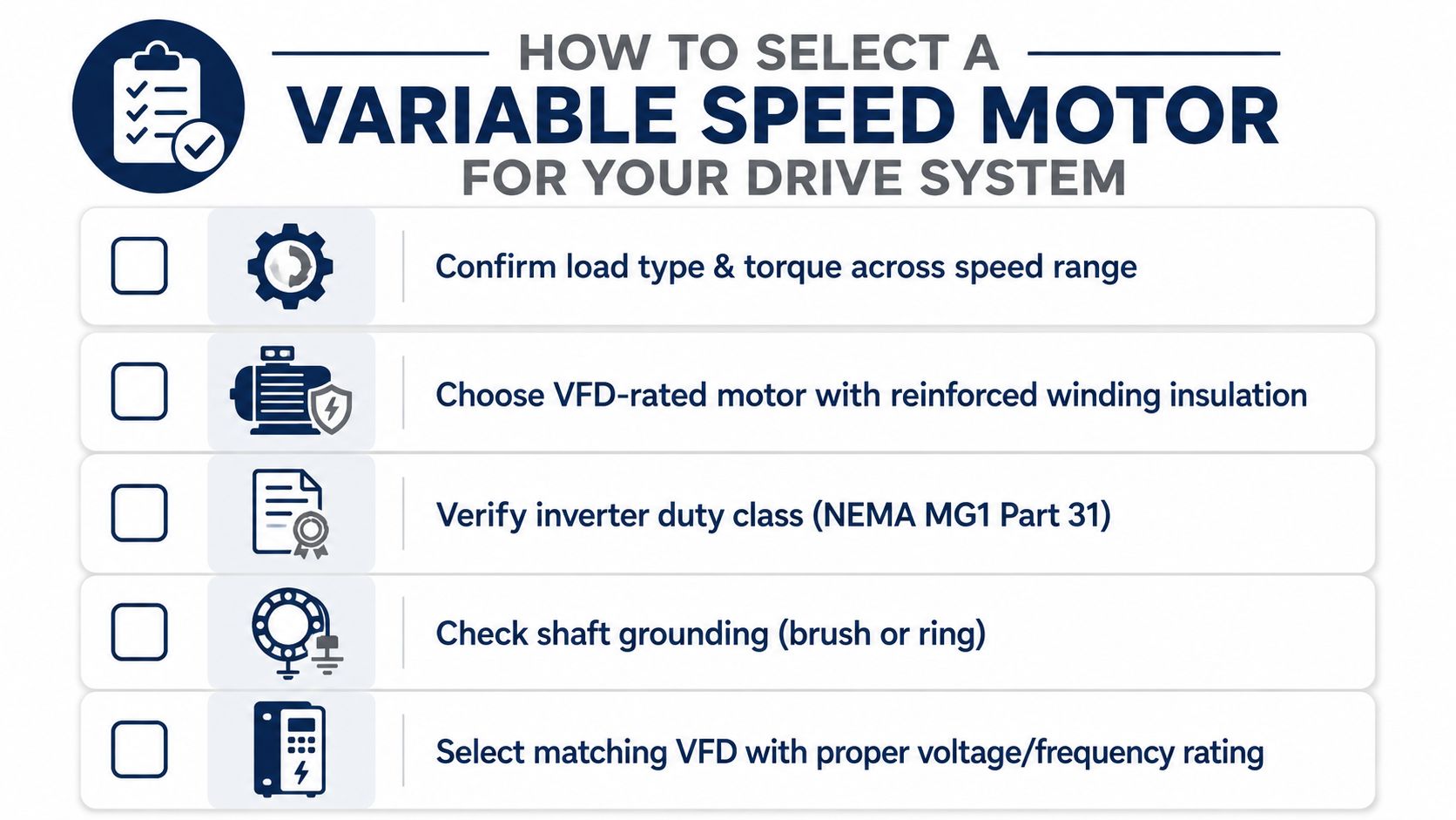
Next, verify that the motor is purpose-rated for VFD service. Look for reinforced winding insulation, suitable thermal performance, and provisions for managing shaft voltage and bearing-current risk. Canadian guidance specifically emphasizes inverter-duty construction and preserved winding design for new and repaired motors exposed to high-frequency switching.
Match the control method
- V/Hz control: Appropriate for straightforward fan and pump duties where torque response and low-speed regulation aren't demanding.
- Sensorless vector control: Useful for general conveyors, mixers, and applications that need better torque control without a physical speed sensor.
- Closed-loop vector or field-oriented control: Suited to hoists, winders, and other duties requiring precise speed and dynamic torque response.
The VFD should be sized from motor full-load current and the actual low-speed torque requirement, not horsepower alone. A drive with a suitable voltage and frequency rating still may be inadequate if the load's current demand exceeds its continuous or overload capability.
Check the environment and retrofit boundary
Confirm ambient temperature, altitude, enclosure requirements, contamination, humidity, cooling airflow, and motor mounting conditions. A clean indoor application and a high-salinity or carbon-black environment impose very different maintenance expectations.
For an existing installation, document the cable route, motor insulation condition, grounding arrangement, PLC interface, feedback devices, gearbox ratio, coupling, and protective settings before selecting replacement equipment. A motor that fits mechanically may still be electrically unsuitable for the new switching waveform.
Comparing Motor Types Used with Variable Speed Drives
Three motor families appear frequently in modern variable speed systems. The right choice depends on the load, control response, efficiency objective, thermal behavior, and the practical limits of a retrofit.
An induction motor uses a rotor that receives its working currents through electromagnetic induction. It remains a flexible choice for many industrial duties because the motor construction is familiar and compatible with common drive control methods. For constant-torque conveyors, mixers, and many compressors, an inverter-duty induction motor is often the most straightforward fit.
A permanent magnet motor uses magnets in or on the rotor. It can provide high power density and strong efficiency performance, but the drive must manage rotor position and control behavior correctly. The design team also needs to consider magnet retention at high temperature and the consequences of bearing currents in the complete motor-drive arrangement.
A synchronous reluctance motor produces torque through the rotor's magnetic reluctance characteristics rather than rotor windings or permanent magnets. It can suit efficiency-focused applications, particularly where the mechanical equipment is sound and the drive system is being modernized.
| Motor Type | Typical Efficiency Class | Speed Range under VFD | Starting Torque | VFD Compatibility Notes |
|---|---|---|---|---|
| Induction motor | IE3 and higher designs are available | Broad, subject to cooling and insulation limits | Strong when correctly controlled and sized | Familiar, flexible, and widely used with inverter-duty construction |
| Permanent magnet motor | IE4 and IE5 designs are available | Broad, with control and thermal limits | Depends heavily on drive commissioning and rotor position control | Requires compatible control, insulation, grounding, and thermal assessment |
| Synchronous reluctance motor | IE4 and IE5 designs are available | Application-dependent | Requires an appropriate drive control strategy | Attractive for efficiency-oriented systems and selected retrofits |
Efficiency class alone shouldn't decide the purchase. A high-efficiency motor paired with poor load matching, unsuitable low-speed cooling, or inadequate harmonic mitigation can deliver a disappointing lifecycle result. Conversely, a familiar induction motor may be the better choice when maintainability, spare availability, and constant-torque performance carry more weight than compactness.
A Lifecycle View of Variable Speed Motor Decisions
A variable speed motor decision should survive five operating phases: specification, installation, commissioning, steady-state maintenance, and eventual retrofit. The purchase price is only one part of the outcome. The rest depends on how carefully the team preserves electrical integrity and verifies the process load.
Specification and installation
During specification, capture the load curve, duty cycle, required speed range, control response, motor thermal limits, cable arrangement, and power-quality requirements. Choose the motor and VFD together, then define the filter, grounding, enclosure, and protection approach before the equipment reaches site.
Installation turns those decisions into physical risk controls. Cable routing, shield termination, grounding continuity, cabinet ventilation, separation from instrumentation, and motor-frame bonding all deserve inspection. A system can have the correct catalog ratings and still fail if installers treat the output cable like ordinary motor wiring.
Commissioning and operation
Commissioning should include parameter verification, motor identification or autotuning where supported, rotation checks, unloaded checks where safe, ramp validation, current review, and baseline vibration measurements. Record the initial operating condition so later changes can be distinguished from original behavior.
During operation, maintenance teams should trend drive faults, motor current, cabinet temperature, vibration, insulation condition, bearing condition, and process performance. Natural Resources Canada notes that VFD efficiency is typically 97% or more at full load, while efficiency falls at reduced load, so the team should assess the complete operating profile rather than relying on a single rated-efficiency value. Industrial asset management guidance can help organize those records around condition, criticality, maintenance history, and renewal planning.
Retrofit and end of life
A late-life drive shouldn't automatically trigger a complete system replacement. Engineers can compare repair, reconditioning, control modernization, motor replacement, and full changeout. The right decision depends on component condition, spare-part availability, safety requirements, software compatibility, motor suitability, and the cost of a planned outage.
Lifecycle insight: The most economical VFD system is the one the plant can specify correctly, commission safely, maintain predictably, and recover quickly when a fault occurs.
For facilities operating across China and Southeast Asia, DUCHENG Industrial provides multi-brand VFD commissioning, troubleshooting, repair, preventive maintenance, on-site reconditioning, spare-parts compatibility review, and smart O&M consulting. Visit DUCHENG Industrial to discuss a variable speed motor or drive-system assessment built around your site's load, installation constraints, and maintenance plan.