
Learn how a variable speed motor AC system works with VFDs, the types available, real-world benefits, and common industrial applications explained clearly.
You're standing in front of a pump or fan that's been running the same way for years, even though the process doesn't need full speed all the time. The valve is doing the throttling, the motor is still burning through power, and the team is left with the same familiar questions every time the bill arrives or the bearing runs hot again. That's where variable speed motor AC starts to matter, not as a buzzword, but as a practical way to match motor speed to the job instead of fighting the load with waste.
In industrial plants, that shift didn't appear out of nowhere. Variable frequency drive technology spread in the early 1970s when energy conservation became a priority, first in process-control uses and later in big pump and HVAC fan applications, and modern standards now formalize drive efficiency classes such as IEC 61800-9-2. That history matters because it explains why today's retrofit decisions aren't just about saving kilowatt-hours, they're about control, reliability, and whether the existing motor and load can live with a drive.
Table of Contents
- Why Variable Speed AC Motors Are Reshaping Industrial Plants
- The Physics of AC Motor Speed in Plain Language
- Main Types of Variable Speed AC Motor Control
- Energy Savings and Process Benefits Explained
- Is Your Existing Motor VFD Ready
- Hidden Risks Drives Introduce and How to Mitigate Them
- Reliability and Maintenance Lessons From the Field
- A Practical Framework for Drive Decisions Across the Lifecycle
Why Variable Speed AC Motors Are Reshaping Industrial Plants
A maintenance crew knows the scene before anyone says a word. A centrifugal pump is running at full speed, the process only needs part of its output, and the valve is pinching the flow to force the system into balance. The motor stays locked to line frequency, the pump wastes energy as pressure loss, and the valve gets punished every time operators chase a setpoint.
That's why variable speed motor AC systems keep replacing old throttling habits in water treatment, HVAC, steel, packaging, and process plants. The drive lets the motor follow demand instead of fighting it, and the effect shows up in more than just the electric bill. Published industry sources commonly report 20% to 50% electricity savings in variable-torque pump and fan applications, with some analyses citing 20% to 65% depending on load profile and control method.
What changes on the plant floor
The biggest shift is not the keypad. It's the control philosophy. With a drive, speed becomes a process variable, so the motor can idle down when the process is light and ramp up only when demand rises. That reduces wasted flow, cuts mechanical stress on valves and dampers, and usually gives operators tighter control over pressure, temperature, or air volume.
A useful rule is simple, if the load is variable-torque, the drive usually has room to pay back. The reason is physical, not marketing. For pumps and fans, the savings come from matching speed to demand, and the system-level losses are usually not in the power electronics themselves but in the motor and load operating point. In practice, that means the plant wins when the speed is right, not when the system tries to turn excess pressure into heat.
Practical rule: If the process already uses a valve, damper, or bypass to control flow, a variable-speed approach is usually worth evaluating before you touch the motor.
For a quick field reference, a good starting point is this variable-speed drive overview, then compare it against your own load and maintenance history. If the asset is a pump or fan, the next question is not whether the motor spins. It's whether it can spin differently, safely, and for long enough to justify the retrofit.
The Physics of AC Motor Speed in Plain Language
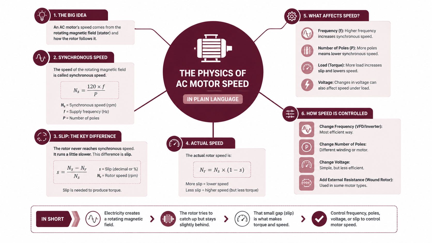
The easiest way to understand an AC motor is to start with the stator field. The drive changes the electrical frequency feeding the motor, and that changes the speed of the rotating magnetic field. The usual shorthand is n = 120f/p, where synchronous speed depends on frequency and the number of poles.
Think of frequency as the pace of the magnetic “push,” and poles as the motor's internal layout that sets how many electrical cycles are needed per revolution. If you lower frequency, the magnetic field turns more slowly, so the rotor follows at a lower mechanical speed. The rotor never quite catches the field, and that small gap is called slip, which is what lets the motor make torque instead of just spinning in place.
Why hertz on the drive matches rpm on the shaft
On a fixed-speed motor, line frequency is fixed, so the shaft speed stays near one operating point. On a drive, the keypad setting changes the frequency, and the speed changes with it. For a technician at the coupling, that means the motor's mechanical speed is no longer tied to the utility frequency in the old way, it's tied to the command the drive is giving.
Below base speed, the drive usually holds roughly the right volts-to-hertz relationship so the motor can keep producing useful torque as speed drops. Above base speed, voltage is limited, so torque falls and the motor moves into a constant-horsepower type of behavior. That matters during commissioning, because a pump that behaves well at 45 Hz may not behave the same way at 70 Hz.
The drive is not “forcing” the motor to slow down. It is changing the electrical pace that the motor follows.
For plant crews, the practical takeaway is this. If the keypad shows a lower frequency, the coupling should be turning slower, unless the load is slipping badly or the system is overloaded. That simple connection is what turns the drive from a black box into a tool you can troubleshoot with meters, trend logs, and a hand on the bearing housing.
Main Types of Variable Speed AC Motor Control
Different control methods solve different plant problems. If the load is forgiving, simple speed control is usually enough. If the load demands precise torque, the drive needs more information and more sophistication.
How the main methods differ
Volts-per-hertz control is the straightforward option. It keeps the voltage and frequency in a set relationship, which is why it works well on fans, pumps, and many conveyors. It's simple to set up, and it does the job when you do not need tight regulation at low speed.
Vector control goes further. By separating torque and flux control, it gives better speed regulation and stronger starting torque, which is why it fits extruders, hoists, and loads that change quickly. It can be sensorless or sensored, depending on whether the drive estimates motor behavior or uses feedback.
Direct torque control pushes response even faster by controlling stator flux and torque error directly. That makes it attractive when the load reacts very quickly and you need the motor to follow without lag.
| Comparison of AC Variable Speed Control Methods | Best Suited Loads | Dynamic Response | Commissioning Complexity |
|---|---|---|---|
| Volts-per-hertz | Pumps, fans, basic conveyors | Moderate | Low |
| Vector control | Extruders, hoists, tighter process drives | High | Medium to high |
| Direct torque control | Web handling, test stands, fast-changing loads | Very high | High |
For the maintenance team, the issue is not which method sounds smartest. It's whether the load needs torque control, speed accuracy, or just a steady reduction in wasted flow. A fan loop that only needs trim control can tolerate a much simpler setup than a crane or rolling line.
The motor nameplate still matters in all three cases. Voltage, current, frame, and duty class shape what the drive can do without overheating the machine or creating nuisance trips. A control method that's perfect on paper can still fail in the field if the motor and load aren't a good match.
Energy Savings and Process Benefits Explained
The savings story becomes clear once you stop looking at the motor by itself. A pump or fan is a variable-torque load, so reducing speed usually cuts required power sharply. Drive control therefore beats throttling, bypassing, or dampering the flow after the fact.
Published industry sources commonly report 20% to 50% savings for these applications, with broader analyses citing 20% to 65% depending on the load profile and control method. A U.S. Department of Energy referenced presentation also says pumps and fans represent about 50% of potential drive applications and that broad VFD use in those sectors could save about 9.5% of total global electrical energy.
Where the improvement comes from
The biggest gains show up when process demand falls and speed follows it. On a centrifugal system, lower speed means much lower flow and pressure demand, so the motor does not keep making extra head that a valve will just waste. On the plant floor, that difference is easy to see long before the energy meter captures the full result.
The process benefits matter just as much. Soft-start behavior reduces water hammer and mechanical shock, which helps piping, seals, and couplings. Tight speed control can also hold pressure or air volume steadier, so operators spend less time trimming valves and more time running the process.
Why throttling wastes so much power
A throttling valve does not reduce the motor's job. It converts extra hydraulic energy into loss. The pump still spins near full speed, the motor still works hard, and the system pays for output that never reaches the process. With a drive, the motor produces only the speed the system needs, so wasted work drops before it becomes heat.
Field insight: If the control element is downstream of the motor, the system is probably paying for avoidable loss.
That is why fan and pump retrofits often improve comfort, pressure stability, and noise at the same time. Lower speed means less turbulence and less acoustic energy, so the plant floor gets quieter when the process backs off. In HVAC loops, that usually means fewer swings, fewer hard starts, and less mechanical wear across the air-moving train.
Is Your Existing Motor VFD Ready
Before anyone orders a drive, the motor needs to be checked like equipment that is about to change how it breathes, heats, and starts. The question is not just whether the shaft turns. It is whether the motor, wiring, protection, and cooling can handle inverter duty without turning a retrofit into a repair job.
Start with the nameplate and construction
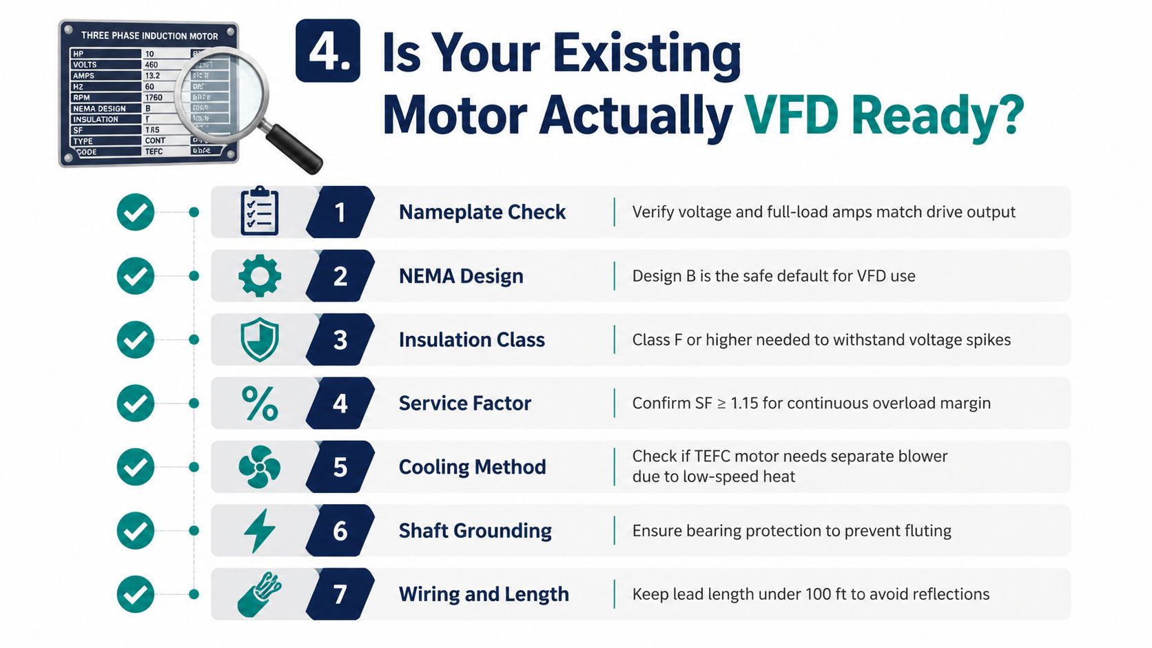
The first pass is the nameplate. Check the voltage, full-load amps, frame, and design type, then confirm the insulation class and service factor. For retrofit work, three-phase motors are strongly recommended for VFDs, while single-phase motors are generally not suitable. A “simple” speed upgrade can turn into a motor replacement if the existing machine is the wrong type (compatibility guidance).
NEMA Design B is usually the safe default for variable-speed service, and Class F or higher insulation is a strong sign the winding can tolerate inverter stress better than an older marginal unit. If the motor is fan-cooled and expected to run at low speed for long periods, confirm whether its own fan can still move enough air, or whether the application needs a separate blower. Low-speed torque and low-speed cooling do not always travel together.
Check the electrical details before the drive goes in
Grounding matters more than many teams expect. The drive changes the waveform, and that can create bearing current paths if the installation is sloppy. Shaft grounding rings, insulated bearings, and proper cable routing are not luxury items on a serious retrofit, they are the things that help prevent avoidable repeat failures.
Overload relays need a second look too. A direct-on-line starter's thermal curve assumes full-voltage behavior, but a drive changes starting current and running heat differently. If you reuse old protection without checking the logic, you can get nuisance trips or poor motor protection.
For wiring and termination details, the connection guide for variable-speed motor systems gives a practical layout to compare against the field installation.
Mechanical fit still decides whether the job succeeds
Alignment, coupling condition, and the actual load profile still matter after the electrical work is done. A motor that was acceptable at constant speed can run hotter at reduced speed if the cooling airflow drops. In one practical sense, the question is not “Will it spin?” It is “Will it spin this way for years without creating new problems?”
If the motor passes the checklist, the next step is deciding how much drive complexity the load really deserves.
Hidden Risks Drives Introduce and How to Mitigate Them
A VFD solves one problem by creating a new electrical environment. In a plant, that means the motor no longer sees the same clean sine wave it had on a direct-on-line starter. The retrofit works best when the team treats that change as a design question, not a bolt-on accessory. The main exposure points are the supply, the motor, and the bearings.
Harmonics and supply-side stress
VFDs are nonlinear loads, so they draw current in pulses instead of as a smooth sine wave. That creates harmonic currents in the supply and can add losses that show up as heating or nuisance interaction with other equipment. On weak networks, long cable runs, or sensitive feeders, the right response is to size line reactors, multi-pulse front ends, or active filtering from measured distortion and thermal impact, not from motor size alone.
A cited study from the University of Cape Town reports that a 12-pulse arrangement with a phase-shifted transformer reduced current distortion from about 95% THDI to about 9.7%, bringing it within IEEE 519-compliant territory in that study (research source). That is a reminder that harmonic control can decide whether a retrofit stays stable or starts causing trouble elsewhere on the bus.
Motor insulation stress and bearing currents
Fast-switching inverter devices create steep voltage edges. Those edges are hard on winding insulation, much like repeated pressure spikes in a pipe wear on weak joints. The same body of evidence shows that harmonic losses can reduce induction motor efficiency under VSD supply, while increasing switching frequency improves motor efficiency in the cited work. Common-mode voltage can also drive shaft currents through bearings, and that is where fluting damage begins if the machine is left unprotected.
A plant with a long motor lead and an older frame has more to think about than a short, clean retrofit on a nearby feeder. The extra voltage stress and bearing current paths are not visible during a quick start test, but they matter over time.
A simple mitigation matrix
| VFD Risk Mitigation Matrix | Root Cause | Mitigation | Relative Cost |
|---|---|---|---|
| Harmonic distortion | Nonlinear rectifier input | Line reactor, passive filter, or multi-pulse front end | Low to medium |
| Winding stress | Fast inverter voltage edges | Inverter-duty motor, output filter, or better cable practice | Medium |
| Bearing currents | Common-mode voltage | Shaft grounding brush, insulated bearing, or both | Low to medium |
The goal is matching protection to the actual exposure. A lightly loaded fan on a clean feeder does not need the same treatment as a large motor on a weak network with a long cable run.
Reliability and Maintenance Lessons From the Field
A steel-mill rolling line once looked like it had a control fault, but that problem sat in maintenance. A 200 kW variable-speed drive kept tripping for months, and board swaps plus restarts only delayed the next fault. Conductive dust had built up inside the cabinet, while clogged heatsink filters trapped heat until the drive ran out of margin.
The maintenance team stopped treating the drive like a sealed box and started treating it like the electrical machine it is. They added thermal imaging under full load, insulation resistance testing on the motor windings, vibration checks on bearings after the retrofit, and trend logging from the drive's own diagnostics. That moved the work from reaction to observation.
A reliability study on an industrial pump application found that moving from throttle-valve control to VFD control improved interruption rate at the motor terminal from 1.5963 to 0.2792 failures per year, although the authors still described the availability gain as marginal. The same study also reported that a 300 kW industrial VVVFD system had a system failure rate of 35.511529 per million hours and an MTBF of 43,048.77077 hours (reliability study). The point is simple. A drive can improve process control and still leave maintenance with real failure exposure.
What the maintenance routine should catch
| Condition Monitoring Task After a VFD Retrofit | Frequency | What It Catches |
|---|---|---|
| Thermal imaging of cabinet hot spots | During full-load operation | Clogged filters, loose terminations, heat accumulation |
| Insulation resistance testing | Quarterly or planned outage interval | Winding degradation, moisture, contamination |
| Vibration checks on bearings | After retrofit baseline, then trend-based | Misalignment, bearing wear, coupling issues |
| Drive diagnostic trend review | Continuous or weekly review | Overtemperature patterns, nuisance trips, parameter drift |
The lesson is direct. Drives need electrical setup and daily housekeeping. Dust, heat, and poor airflow can erase the control benefit if nobody owns them after startup. Plants that already track vibration and thermal data can fold VFDs into that same routine without creating a separate maintenance world.
A Practical Framework for Drive Decisions Across the Lifecycle
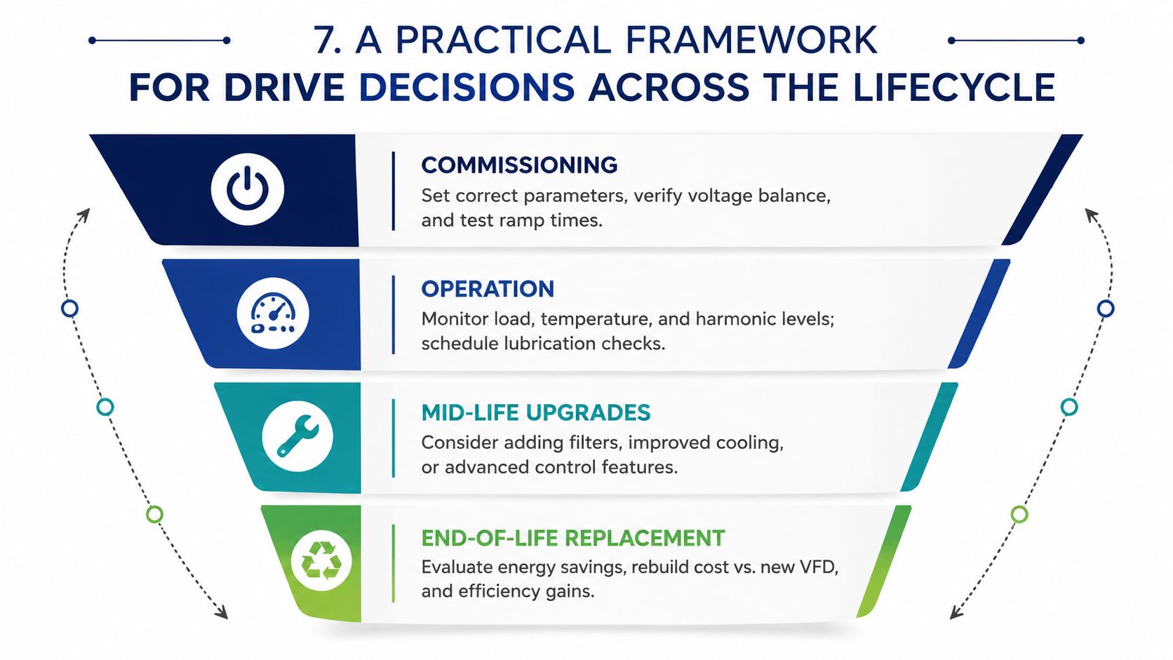
A drive project goes smoother when the plant treats it like a lifecycle asset, not a one-time install. The decisions made at specification time shape commissioning, and the habits set during commissioning shape long-term reliability. If the team only thinks about the retrofit day, the drive usually starts collecting avoidable risk right away.
Four phases that keep the decision clean
Specification is where the load gets matched to the control method, and the motor compatibility check happens before procurement. If the motor is borderline, the right answer may be a motor upgrade, not a drive-only retrofit.
Commissioning is where baselines are captured, parameters are locked down, and operators learn what normal looks like. If the first week is sloppy, later troubleshooting gets harder because nobody trusts the reference point.
Operation is where condition monitoring earns its keep. Harmonic checks, thermal reviews, firmware housekeeping, and regular inspection of cooling paths keep little issues from becoming cabinet failures.
Replacement comes into play when repair costs are climbing, spares are unavailable, or the asset is too obsolete to justify continued recovery. In practice, a power module, fan, or control board can often be repaired or replaced individually, but only if the rest of the unit is still serviceable.
Decision rule: Repair the subsystem when the cabinet, controls, and motor interface are healthy. Replace the whole unit when the repair is only preserving an aging failure pattern.
For teams that need outside support, DUCHENG Industrial provides multi-brand commissioning, troubleshooting, repair, preventive maintenance, and on-site reconditioning for industrial drive systems, which fits well when a plant wants help with diagnosis, controlled restart, or late-life asset decisions. The right question before the next project is simple. Can the existing motor run safely on a drive, can the plant own the new failure modes, and does the maintenance plan match the control plan?
If you're planning a retrofit, start with the motor nameplate, the load type, and the maintenance history, not the drive catalog. DUCHENG Industrial can help assess compatibility, commission the drive, and support repair or reconditioning when the asset is already in service. Bring the project to a team that understands both startup and late-life operation, then make the decision before the plant commits to the wrong architecture.