
VFD display repair demystified. Learn how to diagnose blank screens, fix common HMI faults, and decide between repair and replacement.
You've got the cabinet open, the drive is still there, and the operator panel is dead or unreadable. Before anyone reaches for a new keypad, a ribbon cable, or a spare HMI, treat the blank screen as evidence, not the diagnosis. In the field, vfd display repair usually starts with the power path, because a dark display can point to missing control power, a failed internal supply, a rectifier issue, a blown DC-bus fuse, an open pre-charge resistor, or upstream input loss, not just a bad screen assembly.
The practical mistake is obvious. Techs see a blank display, assume the panel failed, and waste time swapping parts while the fault sits in the drive's auxiliary supply, control board, or communication path. A better workflow is to isolate the symptom layer by layer, confirm what the drive is doing, and only then decide whether the repair is display-only, board-level, or a full drive changeout.
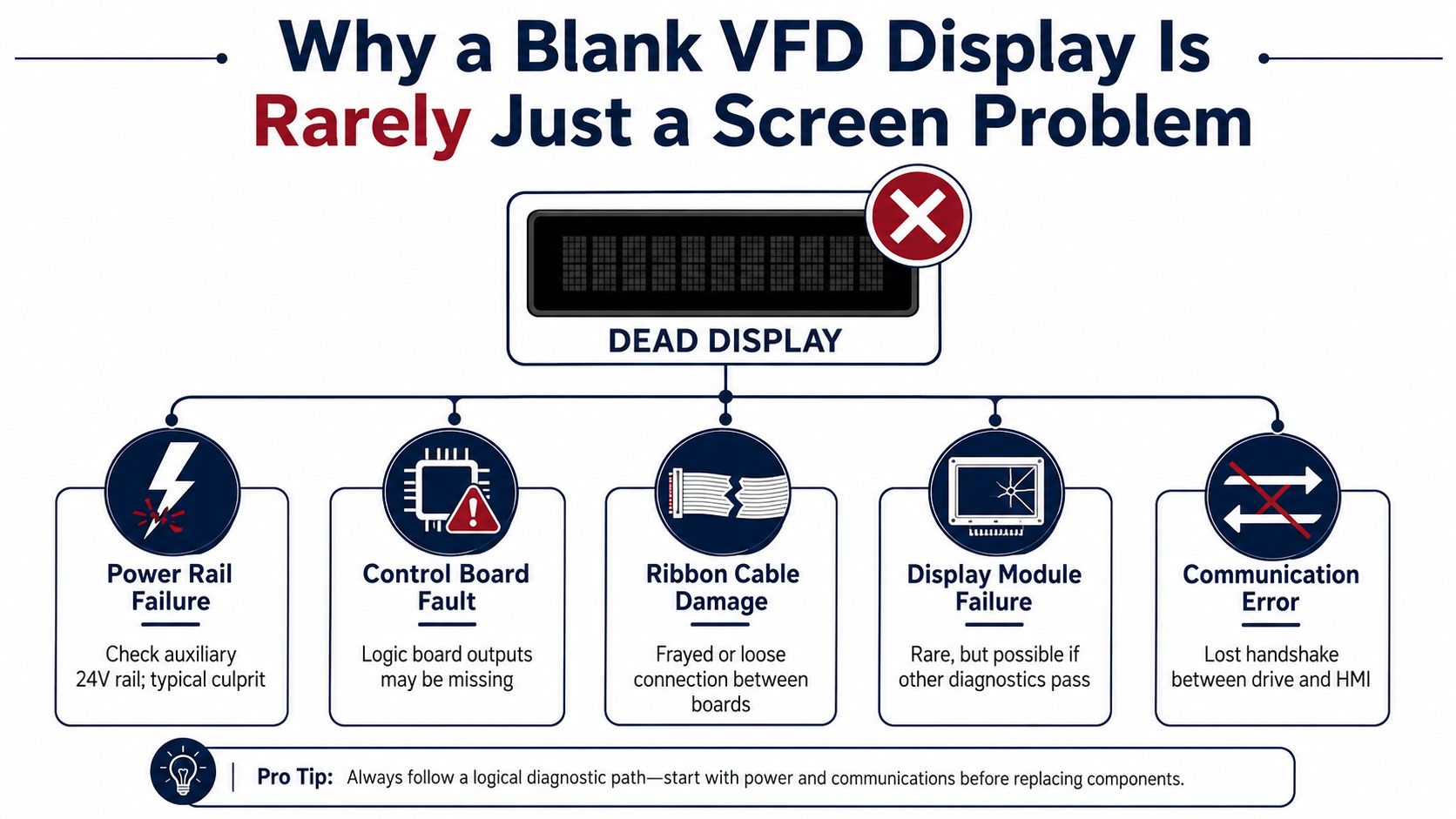
Table of Contents
- Why a Blank VFD Display Is Rarely Just a Screen Problem
- Safety Prerequisites Before Opening the Cabinet
- The Five Failure Modes Behind Display Symptoms
- A Top-Down Diagnostic Sequence You Can Follow on Shift
- Deciding Between Repair, Module Replacement, and Drive Changeout
- Reassembly, Power-Up, and Post-Repair Verification
- Field Checklist and When to Escalate to a Service Provider
Why a Blank VFD Display Is Rarely Just a Screen Problem
A dead display is usually the last thing you notice, not the first thing that failed. The HMI, keypad PCB, ribbon cable, control board, and auxiliary low-voltage rail all meet at the operator interface, so one missing rail or broken handshake can make a healthy-looking panel appear dead. In other words, the display is often the messenger, not the culprit.
Start with the power path, not the bezel
The quickest way to waste an hour is to pull the bezel before checking the drive's own power path. Troubleshooting guidance points to the input voltage, then DC-bus voltage, then auxiliary supply and control-board checks, because many no-display cases trace back to the power side rather than the HMI itself. Healthy low-voltage drives commonly show about 320 VDC on the DC bus for 240 V-class units and about 650 VDC for 480 V-class units, which gives you a useful benchmark before you touch the screen assembly. That benchmark comes from industrial drive troubleshooting guidance on no-display faults.
A blank panel is not proof that the panel failed.
That's the mindset shift. If the bus is wrong, or the auxiliary rail is missing, or the control board isn't waking up cleanly, a ribbon cable reseat won't fix anything. The right question is whether the display module is bad, or whether it's only reporting a deeper drive fault through silence.
What usually fools the technician
A dim or dark screen can be caused by a failed internal power supply, a bad rectifier, an open pre-charge resistor, or unstable upstream input. On rugged industrial sites, loose connections, heat, dust, and contamination make those faults more likely to show up together, which is why a display complaint often hides a broader reliability issue. If you keep that in mind, you stop treating the keypad like a disposable phone screen and start treating it like a diagnostic window into the drive.
Safety Prerequisites Before Opening the Cabinet
No display repair is worth an arc-flash injury or a ruined drive. Lock out the upstream disconnect, verify zero energy with a properly rated meter, and wait long enough for the DC bus to discharge before you touch buswork or control terminals. On larger drives, that wait matters even more because stored energy can linger after the line side looks dead.
Set up the job like an electrical task, not a touchscreen swap
Wear the PPE the cabinet deserves, not the PPE that feels convenient. Arc-rated gloves and safety glasses are the baseline when you're opening industrial enclosures, and you should not work alone near energized buswork if the system can be exposed during testing. If the drive comes out to a bench, build a safe first-power station with an insulated mat, an isolated transformer, and a current-limited variable source so the unit doesn't see full stress on first energization.
Confirm it dead, confirm it again, then touch it.
That habit pays for itself the first time a customer swears the panel is dead and the bus is still floating. ESD precautions matter too, even on tough industrial gear, because keypad PCBs and ribbon cables can be damaged by sloppy handling long before a power device ever fails. A grounded bench, anti-static discipline, and clean connectors prevent a simple display job from turning into a board replacement.
Don't create a second fault while chasing the first
One common mistake is powering a drive repeatedly without giving the bus time to settle, then blaming the display when the control board behaves erratically. Another is moving a removed module onto a dirty bench and flexing the ribbon or the membrane frame. Keep the work area organized, keep loose metal away from exposed terminals, and treat every disassembly step as a chance to preserve evidence instead of destroying it.
The Five Failure Modes Behind Display Symptoms
A blank, dim, frozen, or garbled display usually falls into a small set of fault modes. The trick is not memorizing symptoms, it's matching symptoms to evidence so you know which part deserves replacement. That keeps you from paying for a display module when the control board is the problem.
Compare the symptom to the proof
| Failure mode | What you usually see | What confirms it |
|---|---|---|
| Display module failure | Dim segments, missing rows, broken-looking characters | Backlight current draw is abnormal, segments stay wrong on a known-good drive, other rails are healthy |
| Ribbon cable or connector damage | Intermittent dropout, flicker when the cabinet vibrates, display comes and goes after handling | Continuity changes when flexed, connector oxidation or pin damage is visible |
| Auxiliary supply collapse | Display dies while the drive itself may still run or partially wake | Ripple or low voltage on the logic rail, control power missing at test points |
| Control-board firmware or EEPROM fault | Frozen splash, boot lock, no recovery after restart | Fault memory is retained, boot sequence stalls, supply rails are present but logic never initializes |
| Communication or keypad-encoder fault | Display is alive but buttons do nothing, or the panel won't hand off commands | Keypad inputs don't change state, handshake signals are missing or inconsistent |
The point of that table is simple. You do not need to guess at the failure mode if you can prove which layer is broken.
Read the clues in the fault history
Modern drives store useful history, and older service guidance notes that the last 8 fault, error, or warning messages can be retained in the drive, which helps reconstruct the sequence before a shutdown or display failure (fault history bulletin). That history matters because display symptoms rarely happen in isolation. Overcurrent, DC-bus overvoltage, undervoltage, overheating, ground fault, motor overload, communication errors, and capacitor degradation are all part of the same stress picture, so the screen may be the first thing to go visibly wrong even when the trouble started upstream.
What the bench should tell you
If the panel backlight is dark but the logic rail is steady, that points you toward the display module or its local inverter path. If the keypad wakes only when you flex the cable, the ribbon or connector is guilty until proven otherwise. If the logic never wakes even with the keypad isolated, stop blaming the HMI and go back to the control supply and board-level checks.
A Top-Down Diagnostic Sequence You Can Follow on Shift
The most reliable way to separate a display-only repair from a deeper drive fault is to move from the incoming supply inward, one decision point at a time. That keeps the work orderly when production is waiting and you need evidence, not guesses.
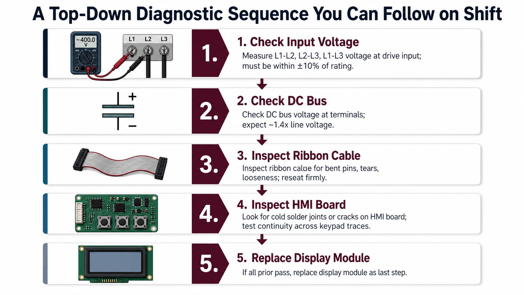
The logic is simple. Start at the supply, then follow the path toward the panel only after each upstream layer checks out.
<iframe width="100%" style="aspect-ratio: 16 / 9;" src="https://www.youtube.com/embed/NgrpYYsMXRg" frameborder="0" allow="autoplay; encrypted-media" allowfullscreen></iframe>Stage 1, prove the drive is actually powered
Measure line-to-line voltage at the drive input terminals and confirm the DC bus is alive. If the bus is missing or unstable, leave the keypad alone. The display cannot wake without upstream power, and a blank screen in that condition is only a symptom.
Stage 2, verify the logic rails
Check the designated low-voltage test points for the control supply, especially the +5 V and +15 V rails where the drive exposes them. If those rails are absent, the control board is not healthy enough to support the HMI. A display swap at that point is a guess.
Stage 3, isolate the keypad and ribbon
Disconnect and reseat the keypad or HMI connection once at each end, then check continuity. Look for bent pins, loose latches, cracked conductors, or connectors that only work when the cabinet is still. In steel mills, tire lines, and chemical sites, vibration-sensitive faults show up often, especially on skids and other high-shock installations.
Stage 4, check the control-board side of the handshake
If the display still will not behave, inspect the board that drives the HMI. Some failures leave the panel blank or frozen even with the logic rail present, because the controller never initializes the interface correctly. At that point, the internal board becomes more likely than the display module itself.
Stage 5, substitute a known-good display only after the earlier checks pass
If the supply is healthy, the board boots, and the cable is sound, a known-good display module is the cleanest proof. If the replacement behaves the same way, the module was not the issue and the fault sits deeper. Use it as the last confirmation, not the first shortcut.
For a broader fault tree and drive troubleshooting and fault-isolation guidance, this sequence keeps the diagnosis grounded before you escalate.
Deciding Between Repair, Module Replacement, and Drive Changeout
Once the display fault is confirmed, the decision isn't just technical. It's about how much of the assembly is damaged, how much support the platform still has, and how much risk you're willing to carry into the next shutdown.
Repair in place when the damage is local
Repair in place makes sense when the evidence points to the ribbon cable, the membrane keypad, or a single cracked piece of display glass, and the drive still has enough service life left to justify the labor. That path works best when the fault stays mechanical or connector-level. If the control board is stable and the rest of the drive is healthy, there's no reason to turn a small interface issue into a larger replacement job.
Swap the module when the panel electronics are the problem
Module replacement is the cleaner choice when the display PCB itself has component damage, the backlight inverter has failed, or the manufacturer still supports a stocked HMI assembly. That's also the path when the board is too densely integrated for worthwhile component-level repair. In practice, it's the middle ground between board surgery and full drive replacement.
If you need a workshop-level repair path instead of an on-site fix, DUCHENG Industrial's repair-services overview is the kind of resource maintenance teams use when the fault has moved beyond a simple panel swap.
Change out the drive when the fault picture gets broader
Drive changeout becomes the right call when the control board also shows faults, the drive is obsolete with no spare support, the module cost climbs too close to a new unit, or the machine is past its practical service life. That's not a failure of maintenance discipline. It's a rational limit on how much labor you invest into a unit that can't be supported cleanly anymore.
If the board is damaged and the platform is obsolete, don't pretend a new display solves the asset problem.
That rule keeps teams from spending hours on a part that can't restore long-term reliability. The evidence from the top-down sequence should make this choice obvious, not emotional.
Reassembly, Power-Up, and Post-Repair Verification
A repaired display can still fail the job if the reassembly is sloppy. Route the ribbon cable without kinks, torque the keypad mounting screws to the manufacturer's value, and reseat the bezel so the cabinet seal returns to its intended IP54 or IP65 condition where applicable. The interface area takes abuse during disassembly, so the mechanical finish matters as much as the electrical fix.
Bring power back in stages
Where possible, energize the control supply first and confirm the keypad wakes, the characters are readable, and the buttons respond. Then apply full mains and verify that the drive accepts commands the way the display says it should. If the screen says one thing and the drive does another, stop and recheck the interface or the control board before returning the unit to service.
Verify function, then verify stability
Run a directed checklist before you hand the drive back. Back up parameters if the platform allows it, clear or record the fault history, and let the drive run with no load while you watch the bus and heatsink behavior. That tells you whether the repair solved the display issue or just masked a bigger problem waiting to return under temperature and load.
Document the fault code, the parts changed, the routing of the cables, and what the post-repair test showed. A clean maintenance log saves the next shift from repeating your work and gives the service team a real baseline if the unit comes back with the same complaint. Good records turn one repair into useful history.
Field Checklist and When to Escalate to a Service Provider
Use a short checklist before you close the job. If you can't check these boxes, don't force the drive back into production just because the display came alive once.
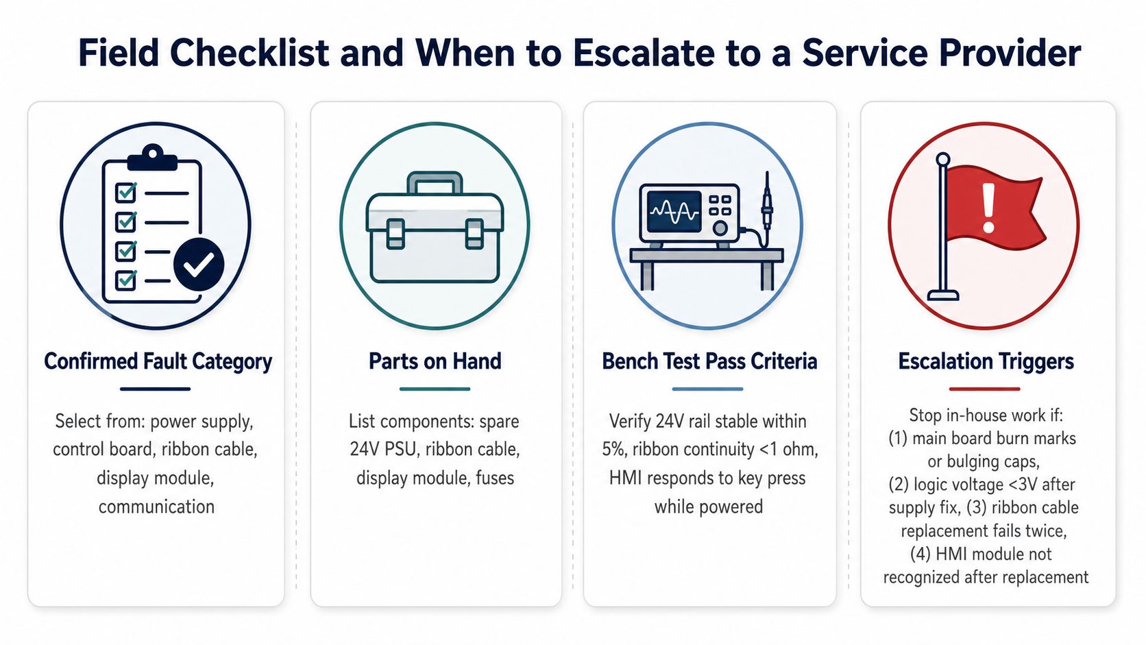
- Confirmed fault category: Decide whether the problem is power supply, control board, ribbon cable, display module, or communication before you close the cabinet.
- Parts on hand: Keep the likely replacements ready, including a spare low-voltage supply section, ribbon cable, display module, and the correct fuses.
- Bench test pass criteria: Confirm the low-voltage rail is stable, the ribbon is continuous, and the HMI responds to key presses while powered.
- Escalation triggers: Stop in-house work if you see burn marks or bulging capacitors on the main board, logic voltage stays too low after a supply fix, the ribbon replacement fails twice, or the HMI isn't recognized after replacement.
Those triggers matter because some faults are no longer panel repairs. Obsolete models with no spare display modules, repeated module failures that point to control-board trouble, evidence of DC-bus or IGBT damage during probing, and drives whose firmware can't be backed up before disassembly all justify escalation. The risk shifts from troubleshooting to containment, and that's when a multi-brand service provider makes more sense than another round of guesswork.
DUCHENG Industrial fits that escalation path when the job has moved beyond a simple display repair. It offers lifecycle VFD services that include troubleshooting, repair, maintenance, spare-part identification, and on-site reconditioning across low-, medium-, and high-voltage drives, so a team can hand off a stubborn fault with the fault log, parameter dump, and photos already organized. If you're facing a blank display that isn't really a display problem, visit DUCHENG Industrial and send the drive details with your maintenance notes so the next step is a real diagnosis, not another parts swap.