
Explore how a vfd for pump application works in real plants. Learn selection, control strategies, commissioning, and lifecycle care for reliable operation.
At 4:40 a.m., a maintenance supervisor is standing beside a vertical multistage pump that has tripped on overcurrent for the third time that week. The discharge valve is partly closed to hold process flow, the motor is still running at full speed, and the suction line has started to chatter. The drive fault is visible, but the actual problem is hydraulic.
That situation is why a VFD for pump application should never be treated as a simple energy-saving accessory. A variable frequency drive changes the speed available to the pump, which changes the operating point, control response, starting behavior, suction margin, electrical loading, and the failure modes the maintenance team will inherit. The useful question isn't only how many kilowatt-hours a VFD might save. It's whether the complete pump system can operate safely and efficiently across its actual duty range.
Table of Contents
- Why Pumps Need Smarter Speed Control
- How the Affinity Laws Drive Pump VFD Savings
- When a VFD Actually Pays for Itself
- Control Strategies Worth Knowing
- Matching the VFD to the Pump
- Commissioning Without Headaches
- Common Faults and How to Mitigate Them
- Lifecycle Services That Keep Pumps Running
Why Pumps Need Smarter Speed Control
The supervisor in that early-morning example doesn't need a brochure promising generic savings. She needs to know why the pump is overloading, whether the suction condition is deteriorating, and whether reducing speed will stabilize the process or create a minimum-flow problem.
A fixed-speed centrifugal pump has one operating speed, even when the process demand changes. Operators then use a discharge valve, bypass line, on/off cycling, or a combination of these methods to force the pump to deliver something other than its natural duty point. The pump continues producing energy, while the valve converts part of that energy into pressure loss and turbulence.
A VFD changes the operating point by changing shaft speed. That can reduce unnecessary throttling, but the practical benefit depends on the relationship between the pump curve and the system curve. A cooling loop, batch process, irrigation network, or water-treatment circuit may have changing flow requirements throughout the day. Matching pump speed to that demand can reduce wasted energy while giving operators a controllable response instead of a binary full-speed start.
The reliability case is often stronger than the energy case
Speed control also changes how the equipment starts and stops. A controlled acceleration ramp can reduce mechanical shock through the coupling, shaft, bearings, and seals. A controlled deceleration ramp can reduce the pressure transient that follows an abrupt stop. These benefits don't make a poor pump selection acceptable, but they can remove stress that a fixed-speed starter applies repeatedly.
The suction side deserves equal attention. A pump that is forced to run against a restricted or unstable suction condition can show symptoms that look like electrical trouble, including fluctuating current, vibration, noise, and nuisance trips. Lowering speed may improve the hydraulic condition, but only if the suction piping, valves, strainer, liquid level, and available NPSH support that operating point.
Field observation: If a pump trips only when the operator trims a valve or changes production demand, inspect the hydraulic operating point before replacing the drive.
A VFD also gives the control system a usable operating range. The operator can select manual speed for a test, use closed-loop pressure or flow control for production, and apply minimum and maximum frequency limits to prevent damaging operation. Those limits matter because a pump isn't automatically safe at every speed the motor and drive can produce.
What the VFD cannot fix
A drive won't correct an undersized suction line, a blocked strainer, a pump running far from its preferred operating range, a leaking mechanical seal, or a system with excessive static head. It also won't make a positive-displacement pump behave like a centrifugal pump. The drive supplies a controllable electrical input, but the pump and piping still determine the hydraulic result.
The most dependable installations begin with a clear duty map. Record the required pressure, flow, liquid properties, suction condition, operating hours, starts, stops, valve positions, and recurring alarms. Then decide whether the main value is energy reduction, process control, reduced mechanical shock, improved starting, or a combination of these outcomes.
How the Affinity Laws Drive Pump VFD Savings
A pump can show attractive cube-law savings on paper and still deliver little at the plant. The result depends on where the pump operates against the system curve, not on the affinity laws alone. For a centrifugal pump operating in a comparable range, flow varies approximately in proportion to speed, head varies with the square of speed, and power varies with the cube of speed. That power relationship explains why a modest speed reduction can sharply reduce input power, provided the hydraulic duty remains suitable.
The relationships are practical, not just theoretical:
- Flow: reducing speed reduces flow in roughly the same proportion.
- Head: reducing speed reduces pump head more sharply because head follows the square of speed.
- Power: reducing speed reduces power most sharply because power follows the cube of speed.
A 20% speed reduction can cut power use by about 50%, while reducing speed by half can reduce power to 12.5% of full load, assuming the pump and system remain within a suitable operating range. These relationships and their efficiency implications are summarized in guidance on VFD energy savings for pumping applications.
Relative scaling before system losses
The table uses rated values rather than implying that one generic pump curve represents every installation. It shows the mathematical scaling of the pump itself.
| Operating Mode | Speed | Flow (m³/h) | Head (m) | Shaft Power (kW) |
|---|---|---|---|---|
| Rated operation | 100% of rated speed | 100% of rated flow | 100% of rated head | 100% of rated power |
| Reduced-speed operation | 80% of rated speed | 80% of rated flow | 64% of rated head | About 51% of rated power |
| Half-speed operation | 50% of rated speed | 50% of rated flow | 25% of rated head | 12.5% of rated power |
Those values describe how the pump curve shifts. They do not identify the final operating point in a real circuit. The system curve includes pipe friction, fittings, valves, heat exchangers, filters, elevation, vessel pressure, and other resistance. Static head remains when speed falls, so the pump may reach its minimum usable speed before the desired flow reduction is achieved.
In a friction-dominated recirculation loop, much of the required head changes with flow. Reducing speed can move the pump toward a lower-head operating point and capture a substantial share of the cube-law benefit. An open system with significant static head behaves differently. The pump must continue supplying the required elevation or pressure, and speed can be reduced only until available pump head approaches that fixed requirement.
That difference separates a credible VFD case from a disappointing retrofit. Before accepting a savings estimate, plot the pump curve and system curve together at the actual operating conditions. Check whether the new operating point stays inside the pump's preferred range, maintains stable suction conditions, and avoids operation near the minimum speed limit. A theoretical reduction in power is irrelevant if the pump begins to cavitate, hunts against the process, or cannot maintain pressure.
Practical rule: Apply the affinity laws to the pump curve, then apply the system curve to the decision. Never use the cube law as a substitute for hydraulic analysis.
A throttling valve and a VFD waste energy in different places. The valve creates a pressure drop while the motor continues turning at fixed speed. The VFD reduces energy supplied to the motor, but it introduces electrical losses, heat, harmonics, and control-system requirements. At low speed, verify motor cooling, suction stability, and the minimum frequency permitted by the pump and process. The correct comparison is fixed-speed operation at the actual duty versus VFD operation at the actual duty, not an idealized pump curve versus a brochure claim.
When a VFD Actually Pays for Itself
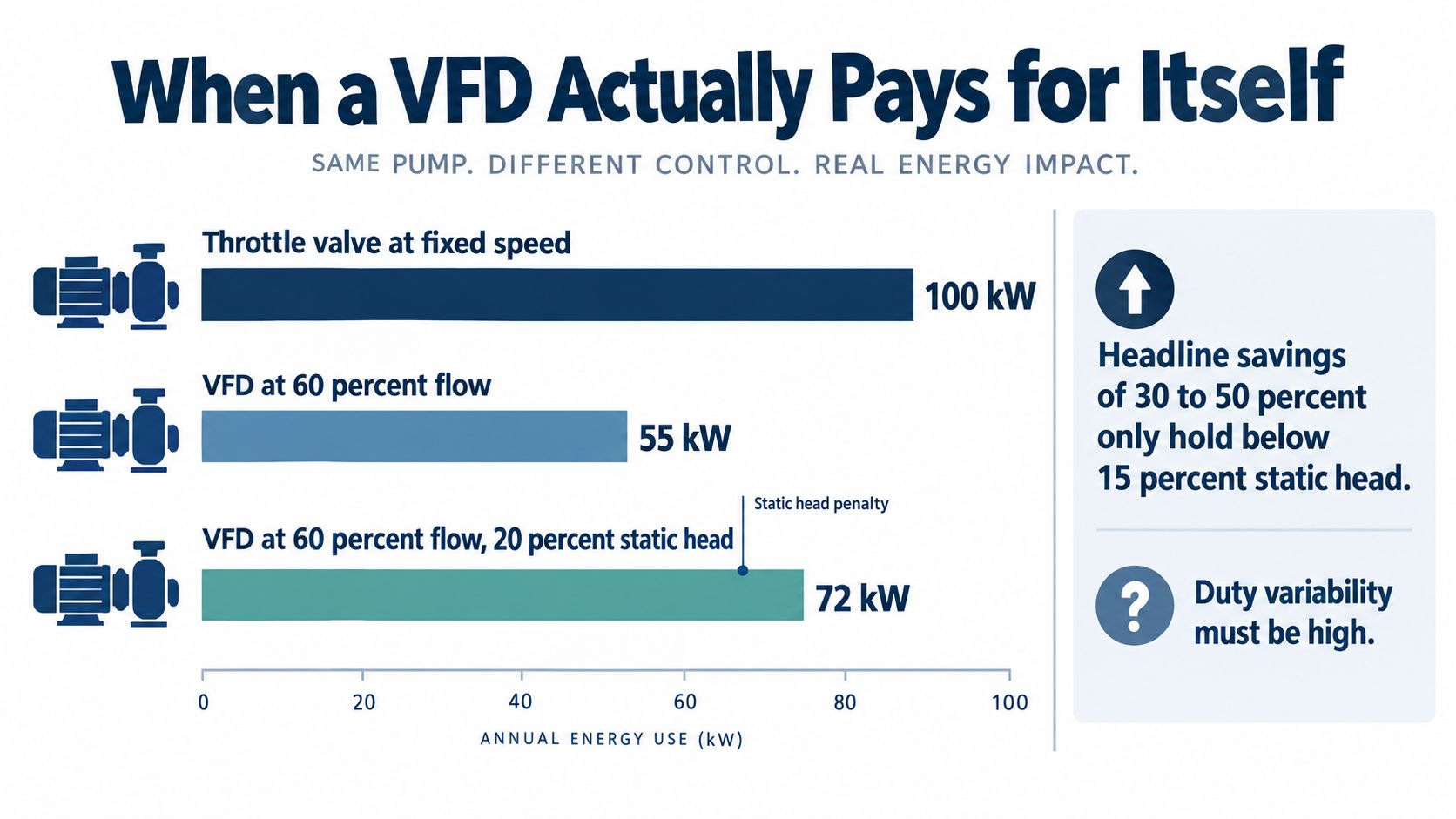
A pump retrofit can show an impressive power reduction on paper and still fail to repay its cost. The familiar claim of 30% to 50% energy savings applies to many rotodynamic pumping installations, but it is not a universal result. U.S. Department of Energy pumping guidance documents that range across many systems while also showing why site conditions determine the outcome.
Start with the system curve, not the affinity laws. Ask how much of the total head is static, how often demand falls below the fixed-speed duty point, and whether the process can accept a lower operating point. A cooling or recirculation system with low static head and frequent load changes is usually a stronger candidate than a process pump that must maintain high pressure at nearly every flow.
Use a static-head screen before building the ROI
A maintenance manager can make a useful first-pass assessment before commissioning a full energy study:
- Collect the pump curve family. Obtain curves for the installed impeller and, where available, different operating speeds.
- Estimate the system curve. Include pipe friction, fittings, valves, equipment losses, elevation, and vessel or discharge pressure.
- Mark static head. Separate fixed elevation or pressure requirements from friction-related head.
- Compare the shares. Systems with under 20% static head are generally strong VFD candidates. Systems with over 50% static head are usually poor candidates for energy savings, as outlined in practical guidance on VFD suitability for pumps.
- Map the duty duration. Record how long the pump operates at reduced demand rather than relying on its nameplate rating.
Treat a projection above 10% savings cautiously when static head is high unless measured data supports it. That threshold is an engineering screen, not a guarantee.
Look beyond the electricity meter
Energy is only one part of the return. A VFD can reduce throttling losses, lower peak electrical demand, limit hard starts on large motors, and make pressure or flow easier to control. The maintenance benefit may come from fewer pressure shocks, fewer starts, less valve intervention, and steadier operation rather than a dramatic drop in average power.
A high-static-head boiler-feed or transfer pump may offer limited energy savings because the pressure requirement remains substantial. Controlled starting, surge reduction, and process stability can still justify the drive when those issues cause failures or production interruptions.
Check the risks that energy calculators often omit. Plot the proposed operating points against the system curve, then verify suction conditions, harmonic requirements, and the pump's minimum permitted speed. A drive that saves power but causes unstable suction, motor overheating, control hunting, or operation below the pump's safe speed will transfer the cost to maintenance.
Compare measured fixed-speed performance with the proposed VFD operating map. Record motor current, flow, discharge pressure, suction pressure, valve position, and operating state across representative production conditions. Then calculate the usable speed range and confirm that the pump remains inside its preferred operating region.
The right ROI question is direct: how much of the pump's work is avoidable friction, how often can the process accept lower speed, and what reliability problems must the drive solve to earn its place?
Control Strategies Worth Knowing
A VFD can be operated in several ways, and the control method determines how much responsibility remains with the operator. A speed command that works well for a constant-pressure booster isn't automatically appropriate for sludge transfer or a cooling-tower loop. The best strategy is the least complicated one that protects the pump and maintains the required process variable.
| Strategy | Response | Pump Protection | Complexity |
|---|---|---|---|
| Direct manual speed | Immediate operator command, limited automatic correction | Frequency and current limits, if configured | Low |
| Closed-loop PID | Continuously adjusts speed from pressure, flow, level, or differential pressure feedback | Setpoint limits, ramp limits, dry-run logic, and sensor alarms | Moderate |
| Pump-specific anti-cavitation logic | Reduces or limits speed when suction conditions become unsafe | Helps protect the impeller and seals when NPSH margin tightens | Moderate to high |
| Water-hammer avoidance ramps | Gradual acceleration and deceleration reduce hydraulic transients | Protects piping, check valves, supports, and connected equipment | Low to moderate |
Direct speed is useful for testing
Manual speed control is valuable during commissioning and troubleshooting. It lets a technician observe flow, pressure, current, vibration, and suction behavior at selected speeds without introducing a control loop that may mask the underlying problem.
Its weakness is operator dependence. One person may run the pump conservatively, while another may push speed higher to recover flow without checking suction conditions. Manual operation should therefore have hard frequency, current, minimum-flow, and process-pressure limits.
PID control earns its place when the sensor is trustworthy
A closed-loop PID is usually the practical choice for constant-pressure boosting, differential-pressure control, and flow regulation. The drive compares the measured process variable with the setpoint and adjusts speed to reduce the error.
PID control fails when the transmitter is installed in a poor location, the signal is noisy, the process has excessive delay, or the gains are tuned for a different hydraulic condition. A pump can hunt between speeds, repeatedly cross a protection limit, or create pressure oscillations if the loop is tuned aggressively.
The sensor must be treated as part of the pump protection system. Verify its range, location, impulse connection, signal integrity, and failure response. Set a safe fallback speed or shutdown action for a lost or implausible signal.
Specialized logic protects against specific hydraulic risks
Anti-cavitation logic can derate speed when suction conditions deteriorate, but it needs a meaningful input. That may be suction pressure, liquid level, flow, calculated NPSH margin, or a validated combination of signals. It isn't a substitute for correcting a blocked suction line or inadequate liquid supply.
Water-hammer avoidance is simpler. Use acceleration and deceleration ramps that match the pipe volume, check-valve behavior, and measured surge response. A ramp that looks gentle on the drive display may still be too abrupt for a long liquid column.
For a broader comparison of operating modes and commissioning considerations, see this guide to VFD control methods. The key is to match the control strategy to the duty, not to enable every available feature.
Matching the VFD to the Pump
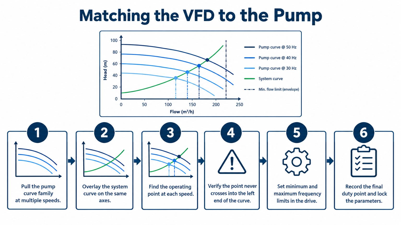
A drive that matches the motor can still be wrong for the pump. Start with the pump curve family at several speeds, overlay the estimated system curve, and mark the intersection for every proposed duty point. Check startup, normal production, reduced demand, emergency operation, and any permitted high-speed condition. The system curve, including static head, determines where the pump will operate, so affinity-law estimates alone cannot establish savings or safe limits.
A centrifugal pump normally presents a variable-torque load. Torque falls with speed, which usually simplifies VFD sizing when the motor, drive, cooling method, and operating envelope are matched correctly. Positive-displacement pumps, slurry pumps, and high-inertia equipment can require higher starting torque, longer acceleration, greater overload capacity, or a different braking arrangement.
Set limits from the hydraulic envelope
Do not choose the minimum frequency because the keypad allows it. At low speed, the motor's own cooling may be inadequate, while the pump can fall below its minimum continuous flow or lubrication requirement. The lower limit depends on motor construction, cooling, bearing arrangement, liquid, seal design, pump type, and the manufacturer's operating instructions.
A minimum operating range of roughly 25 to 30 Hz is common in some installations, but it is not a universal setting. Confirm it against the motor and pump documentation. Set the limit from the hydraulic and mechanical envelope, not from a copied parameter set.
The upper limit needs the same scrutiny. Higher speed changes required head, power, and NPSH, and the system curve can push the operating point into an unsuitable region. As with any adjustable-speed application, consider system curve and static head when estimating actual savings and operating limits. Adjustable-speed pumping guidance from the U.S. Department of Energy
NPSH changes with operating conditions
Lower speed can reduce the pump's NPSH requirement and improve available margin. That benefit disappears if suction piping is restricted, liquid temperature is high, tank level is low, or air enters the suction line. Higher speed raises NPSH required, so recheck suction conditions before permitting operation above nominal speed. A speed increase that looks acceptable on a curve can expose the maintenance team to cavitation, vibration, and seal damage.
Use this matching checklist:
- Motor data: Enter rated voltage, frequency, current, speed, power factor, and thermal information accurately.
- Service conditions: Check altitude, ambient temperature, enclosure cooling, and any required derating.
- Cable installation: Assess long motor leads for reflected-wave stress, voltage rise, insulation condition, and grounding quality.
- Output protection: Consider a dV/dt filter or sine filter for older motors, long cables, or strict insulation and EMC requirements.
- Operating envelope: Set minimum and maximum frequency, current limits, minimum flow protection, sleep and wake behavior, and safe restart logic.
- Mechanical limits: Confirm bearing speed, seal limits, coupling condition, vibration behavior, and the pump's preferred operating region.
Record the approved duty points and the reason for every limit in the final parameter set. Keep that configuration controlled. Informal changes across shifts make hydraulic and reliability faults much harder to trace.
<iframe width="100%" style="aspect-ratio: 16 / 9;" src="https://www.youtube.com/embed/jZaB5n24HRQ" frameborder="0" allow="autoplay; encrypted-media" allowfullscreen></iframe>Commissioning Without Headaches
Commissioning should prove that the motor, drive, pump, control loop, and hydraulic system work together. It shouldn't be treated as a keypad exercise. A technically correct drive can still trip if the motor rotation is wrong, the pump is air-bound, the PID sensor is badly located, or the deceleration ramp creates a surge.
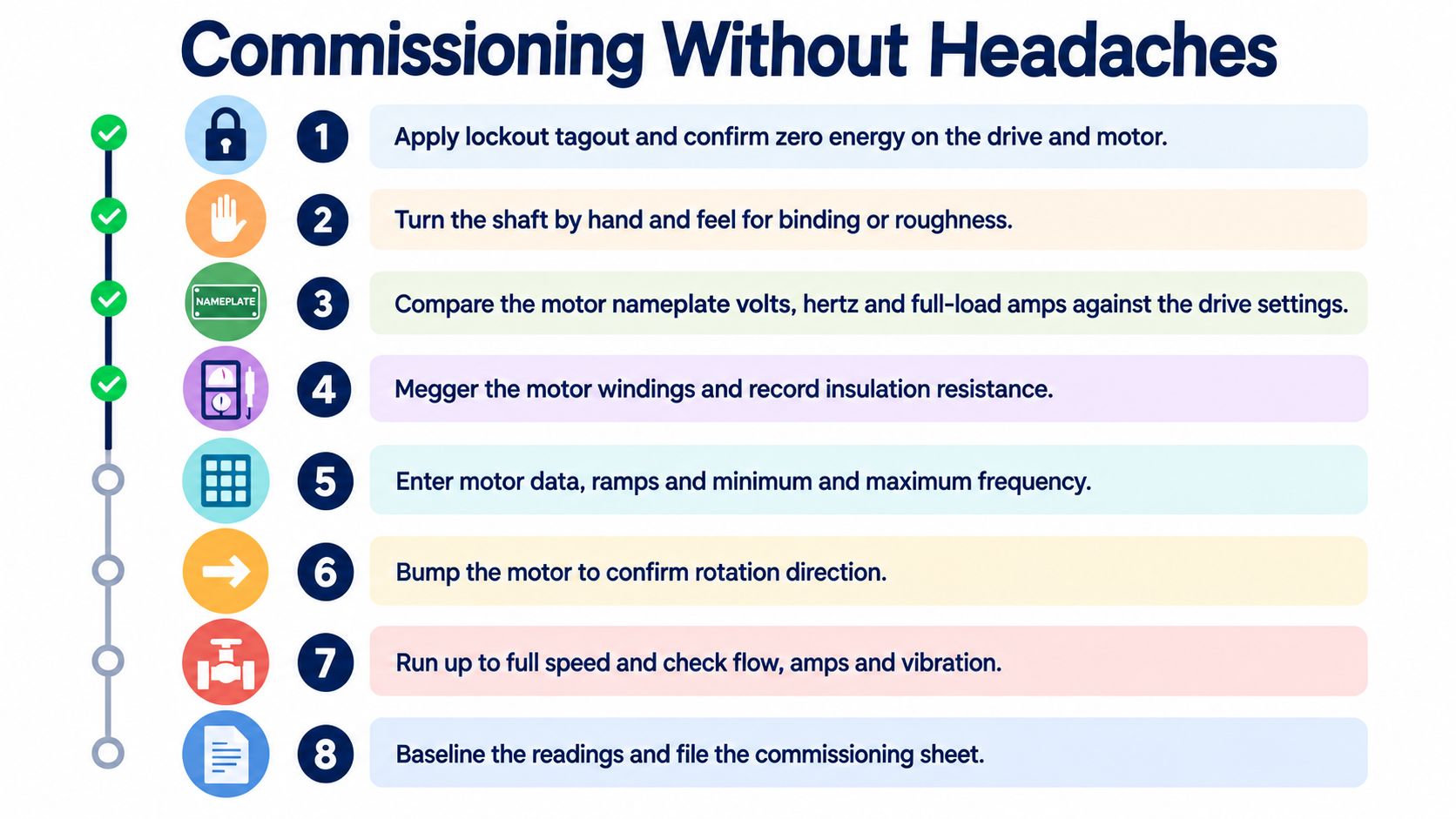
Start with isolation and verification. Apply lockout and tagout, confirm zero energy, inspect the coupling and guards, and turn the shaft by hand where the equipment design permits. Check the motor nameplate against the values programmed in the drive. Record insulation measurements according to the site procedure and motor requirements before energizing.
Prove rotation before loading the pump
With the coupling safely managed according to the equipment procedure, bump the motor at low frequency and confirm direction. Incorrect rotation can damage the process, produce abnormal hydraulic behavior, and create a misleading current or vibration signature. Confirm direction again after coupling if the mechanical arrangement makes that necessary.
Run at low speed long enough to identify binding, abnormal noise, unstable suction, or unexpected current. Then increase speed in controlled increments while watching discharge pressure, flow, motor current, vibration, bearing temperature, and seal condition. Don't tune the PID while the mechanical and hydraulic basics remain unverified.
Tune the loop in a deliberate order
A practical tuning sequence is:
- Set conservative acceleration and deceleration ramps.
- Disable integral action temporarily.
- Introduce proportional gain until the process responds promptly without hunting.
- Add integral action gradually to remove steady-state offset.
- Restore protective limits and test sensor-failure behavior.
- Confirm that the pump doesn't repeatedly cross its minimum-speed or minimum-flow boundary.
The process variable should be measured where it represents the actual duty. A pressure transmitter close to the pump may not represent the pressure at the controlled user, while a flow transmitter installed near severe turbulence may produce unstable feedback.
Set ramps against observed hydraulic behavior. If a stop command produces a surge, lengthen the deceleration ramp and inspect check-valve timing, air chambers, bypass arrangements, and column-separation risk. A longer ramp may reduce the hydraulic event, but it must still meet the process's safe-stop requirement.
For a field-ready preparation and handover sequence, use this VFD commissioning checklist. During the first week, trend bearing temperature, current at known duty points, vibration, harmonic levels where filters or mitigation equipment are installed, and every false trip. Capture the tuned parameters, baseline readings, alarm reactions, and change-log entry so the next shift inherits a known operating state.
Common Faults and How to Mitigate Them
The drive fault code is an observation, not always the root cause. A suction-side NPSH problem can look like an overcurrent or overload event. A long motor cable can produce insulation stress that appears only after the system has been operating for some time. A harmonic issue may show up as DC-bus instability near other large loads.
| Symptom | Root Cause | Mitigation |
|---|---|---|
| Instantaneous overcurrent during a demand change | Acceleration is too fast, the pump crosses an unstable hydraulic region, or the mechanical load is binding | Review the fault snapshot, lengthen the ramp, inspect the pump and coupling, and verify the operating point |
| Bearing noise or repeated bearing damage | Common-mode shaft current and bearing fluting | Check grounding and shaft-current paths, then evaluate insulated bearings or shaft-grounding measures |
| DC-bus or input-related trips near large loads | Harmonic distortion, supply impedance, or interaction with other power electronics | Perform harmonic analysis and consider line reactors, DC chokes, or active filtering |
| Current fluctuation with suction noise and vibration | Low NPSH available, air ingress, blocked suction path, or poor liquid level | Check suction pressure, liquid level, strainer, valves, piping leaks, and minimum-speed logic |
| Pressure spike after a stop command | Deceleration is too short, check-valve timing is poor, or the liquid column is separating | Slow the ramp, review surge behavior, and coordinate drive settings with hydraulic protection |
Read the fault log before changing parameters
The useful clues are often in the sequence around the trip. Record speed reference, actual speed, output current, DC-bus voltage, pressure, flow, suction condition, and the preceding command. An overcurrent that occurs immediately during acceleration points toward a different investigation than an overload that appears after the pump reaches steady speed.
If the fault coincides with suction chatter, don't increase the current limit or repeatedly reset the drive. Check the suction system first. Running harder into a collapsing suction margin may damage the impeller, seal, and bearings while making the electrical symptom more persistent.
Treat electrical side effects as design issues
VFD output pulses can stress older motor insulation, particularly with long motor leads. A dV/dt filter or sine filter may be appropriate after checking the motor, cable length, switching behavior, and grounding arrangement. The filter must be selected and installed as part of the drive system, not added casually after a failure.
Harmonics also deserve measurement rather than assumption. Line reactors and active filters can help, but the correct choice depends on the supply, drive population, loading, and compliance requirement. Shaft-grounding devices and insulated bearings can address bearing-current paths, but they won't compensate for poor cabinet bonding or an incomplete grounding design.
Water hammer requires hydraulic diagnosis. A slower stop may help, but so may check-valve maintenance, air management, bypass design, or a different control sequence. Field-proven mitigation starts with identifying the mechanism that creates the pressure transient.
Lifecycle Services That Keep Pumps Running
A pump VFD is a lifecycle asset, not a box that disappears after commissioning. The commissioning baseline becomes the reference for every later fault investigation. Without it, technicians are forced to guess whether a current reading, vibration level, temperature, or PID response is normal.
A useful handover includes the final motor and drive data, minimum and maximum frequency, acceleration and deceleration ramps, PID setpoints and gains, current limits, alarm reactions, sensor scaling, communication settings, and approved restart logic. Add insulation measurements, vibration readings, bearing temperatures, representative current values, and a copy of the fault-log state at handover.
Preventive work should follow failure mechanisms
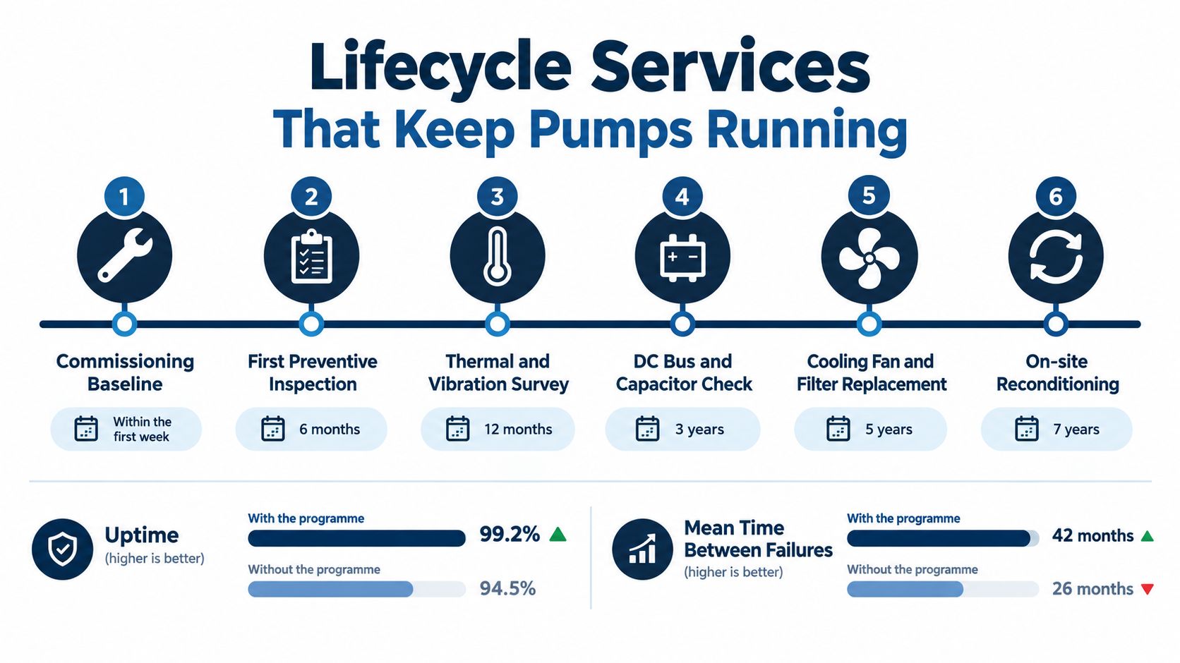
A practical maintenance program focuses on the conditions that age the drive and pump:
- Thermal condition: Inspect cabinet ventilation, cooling fans, heat sinks, and power connections. Use thermography on power cabling and terminations during an appropriate operating condition.
- Contamination: Check dust, moisture, salt, carbon residue, and chemical deposits before they become conductive or restrict cooling.
- Mechanical trend: Compare pump vibration and bearing temperature with the commissioning baseline, not just with a generic alarm limit.
- Electrical quality: Review supply behavior, harmonic measurements where relevant, motor-cable condition, grounding, and filter performance.
- Control integrity: Verify transmitter calibration, PID response, alarm handling, firmware records, and unauthorized parameter changes.
- Documentation: Update the change log after every repair, adjustment, restart, and controlled bypass.
A quarterly visual and filter inspection may be appropriate for a clean indoor cabinet, while harsher environments demand more frequent attention. Annual thermal and electrical surveys can reveal loose connections or deteriorating components before a trip. The schedule should follow contamination, heat, humidity, load, and downtime exposure.
Repair, reconditioning, and replacement are different decisions
A failed drive may need a component-level repair, a workshop overhaul, an on-site reconditioning process, or full replacement. The correct choice depends on fault history, parts availability, age, insulation and power-section condition, criticality, and the time available during a shutdown.
On-site reconditioning can make sense for large or medium-voltage equipment that is difficult or risky to transport. Workshop repair may be more suitable when bench diagnostics and controlled functional tests are required. A replacement assessment should also examine whether the pump, motor, cables, filters, sensors, and control architecture remain compatible with the proposed drive.
Spare strategy should match the consequence of downtime. A hot spare costs money to carry and maintain, but an emergency callout can cost more when the pump supports a continuous process with little production flexibility. Record compatibility carefully, including firmware, power class, control cards, cooling arrangement, enclosure, and application parameters.
DUCHENG Industrial provides multi-brand VFD commissioning, troubleshooting, preventive maintenance, workshop repair, on-site reconditioning, spare-parts identification, and controlled restart support for industrial drive systems. If a pump drive has become a recurring source of trips, compare the fault history and baseline data before deciding whether to repair, recondition, upgrade, or replace it.
If your pump is still being controlled by throttling, start by recording its real operating points, suction condition, valve position, current, and fault history. Then ask DUCHENG Industrial to help assess commissioning, troubleshooting, preventive care, or on-site VFD reconditioning against the hydraulic and electrical limits of your installation.