
VFD harmonics problems cause hidden damage and failures. Learn to diagnose IEEE 519 compliance, measure THD correctly, and select the right mitigation
VFD harmonic problems are rarely caused by one drive alone. They are system-level interactions between the drive's rectifier, source impedance, other nonlinear loads, and operating conditions, so the first step is always a PCC measurement under representative load, not a terminal THD reading.
A production line may run normally for months, then start tripping after a drive replacement, a capacitor-bank change, or a shift to generator supply. The maintenance team checks the motor, replaces the drive again, and tightens every termination. Meanwhile, a transformer cabinet runs hot, control boards fault intermittently, and a neutral conductor develops an audible buzz. Those symptoms can look unrelated, but harmonic current often connects them.
The practical mistake is treating distortion as a fixed property printed on a VFD datasheet. The same drive can behave differently on a stiff utility bus, a lightly loaded transformer, a generator-fed system, or a shared bus with many other nonlinear loads. Diagnosis has to follow the electrical system, not just the drive nameplate.
Table of Contents
- When Trips and Overheating Hide a Harmonic Root Cause
- How VFD Harmonic Problems Are Created and Measured
- Where and How to Measure Harmonic Distortion Correctly
- Comparing Harmonic Mitigation Strategies for VFD Systems
- Why Operating Conditions Make One Filter Inadequate
- System-Level Diagnostic Workflow for Plant Engineers
- Troubleshooting VFD Harmonic Issues in the Field
- Planning Lifecycle Harmonic Compliance and Maintenance
When Trips and Overheating Hide a Harmonic Root Cause
A line trips during acceleration. The drive fault history points to overcurrent, so the first response is to inspect the motor and replace the drive. A few weeks later, the replacement trips in the same operating window. The transformer feeding the line is warmer than nearby units, the panel neutral is noisy, and a sensitive controller resets without a clear input fault.
That pattern deserves a power-quality investigation. Repeated trips, unexplained heating, capacitor stress, and intermittent control faults can all accompany harmonic distortion, particularly when several nonlinear loads share the same source. A drive may be operating within its own terminal measurements while contributing to an unacceptable condition farther upstream.

Symptoms that deserve a system check
The symptom itself doesn't identify the cause. Transformer heating may result from aggregate current distortion, resonance, or excessive loading. A nuisance trip may involve protection coordination, voltage distortion, or interaction between multiple drives. Neutral heating can point toward zero-sequence harmonic currents, not just an uneven phase load.
Start by separating three questions:
- What is the drive doing? Check its input current, output condition, fault history, and operating point.
- What is the bus experiencing? Measure voltage and current distortion at the relevant point of common coupling.
- What else changes at the same time? Record capacitor switching, bypass operation, generator transfer, parallel-drive starts, and production loading.
The distinction matters because IEEE 519 assigns different responsibilities to users and utilities. Users control the current distortion they inject, while utilities and system designers maintain acceptable voltage quality. The standard's framework covers static converters, harmonic control, reactive compensation, disturbance limits, and equipment and communication impacts, with the current edition approved and published in 2014. The IEEE 519 standard overview explains why assessment belongs at the system interface rather than only at one drive.
Practical rule: If a replacement drive produces the same trip pattern as the original, stop treating the drive as the only suspect.
A terminal reading can identify what the VFD is drawing at that instant. It can't show how the entire drive population interacts with transformer impedance, capacitor banks, generators, UPS equipment, protection, and sensitive controls. That is why a measurement-first response usually costs less than repeated component replacement.
How VFD Harmonic Problems Are Created and Measured
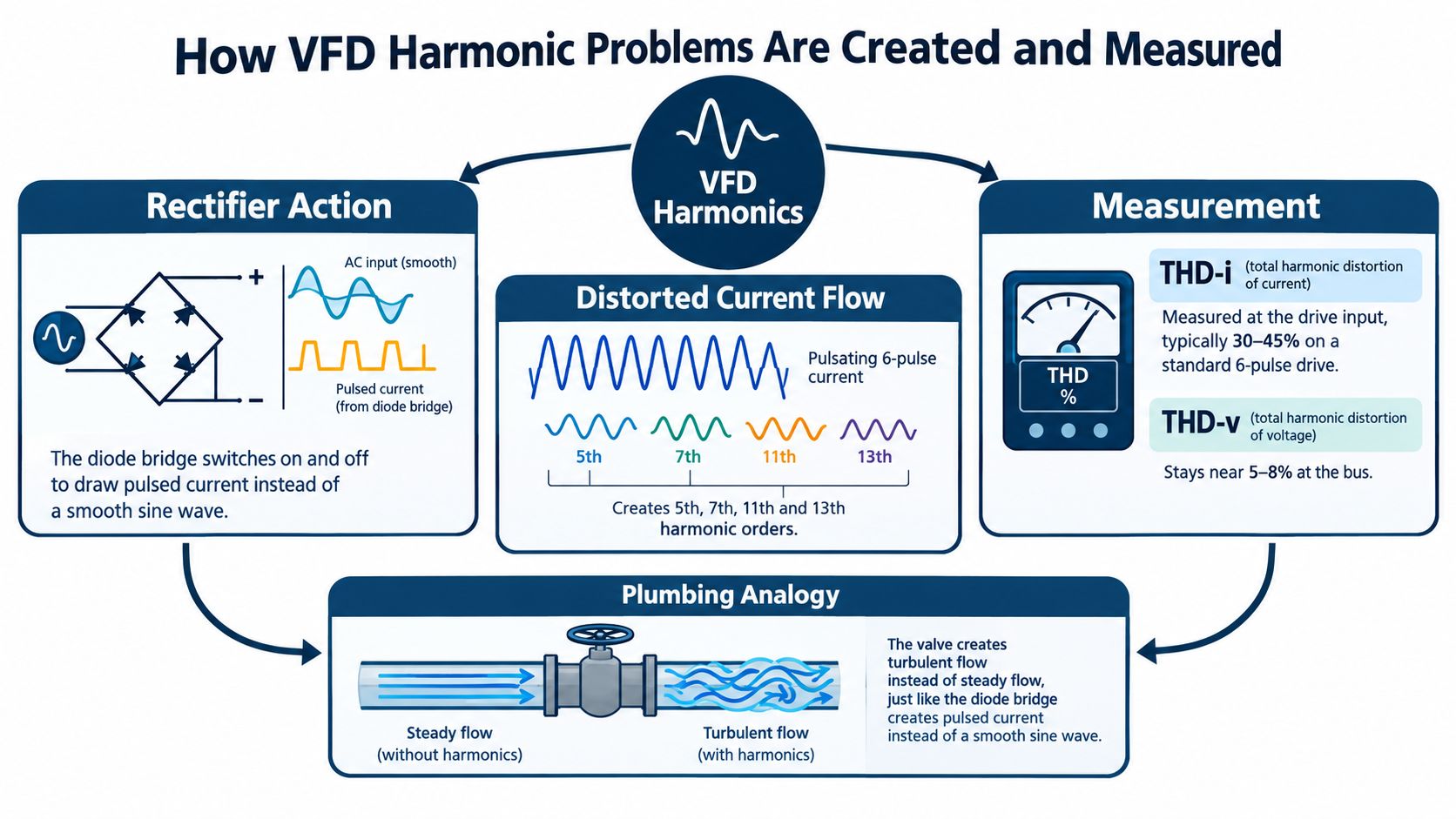
A VFD's input rectifier behaves more like a valve than an open pipe. It conducts during portions of the AC waveform, charging the DC link in pulses rather than drawing smooth sinusoidal current. Those pulses contain harmonic components, and the resulting voltage distortion depends on the source impedance and the combined behavior of other nonlinear loads.
The plumbing analogy is useful in the field. One pulsing valve may cause little visible disturbance in a large pipe, while many valves operating on a restricted pipe can create turbulence and pressure fluctuations. Electrically, a single drive may be acceptable on a strong source, while an aggregated drive population can create transformer heating, capacitor stress, nuisance tripping, resonance, and interference with controls.
Three measurements that shouldn't be confused
Current distortion describes how far the current waveform departs from a clean fundamental waveform. It reflects what the nonlinear load injects into the electrical system.
Voltage distortion describes the quality of the voltage waveform at the bus or PCC. Current distortion creates voltage distortion through system impedance, so two identical drives can produce different voltage results on different buses.
Total Demand Distortion, or TDD, relates harmonic current to the maximum demand load current at the PCC. That makes it more useful for system-level compliance than an isolated instantaneous current THD value. IEEE 519 current limits depend on the ratio of available short-circuit current at the PCC, (I_{SC}), to maximum demand load current, (I_L). A strong source can absorb more injected current than a weak industrial bus.
The 2014 framework identifies 5% for an individual voltage harmonic and 8% total harmonic voltage distortion for systems at or below 1 kV at the PCC. It also gives more restrictive total voltage distortion limits as voltage rises, reaching 1.5% at 161 kV. These are voltage benchmarks, not interchangeable VFD input-current THD values. The IEEE 519 application guidance and limit summary provides the relevant distinction.
A practical explanation of the drive itself is available in this guide to how a variable frequency drive works. For harmonic diagnosis, however, understanding the rectifier is only the beginning. The measurement location, source strength, load combination, and operating state determine whether the distortion is a plant problem.
Where and How to Measure Harmonic Distortion Correctly
A drive can appear to be the problem when the actual issue is the bus feeding it. Start the survey at the point of common coupling, then work toward the VFD and other major nonlinear-load groups. The PCC shows the condition seen by the upstream source. A terminal measurement remains useful, but it cannot replace the system view.
Use a power-quality analyzer or portable harmonic meter that records voltage, current, demand, power factor, individual harmonic orders, THD, and TDD. Check the connection method, current-transformer orientation, voltage category, and logging settings before energizing the test. A handheld screenshot may confirm a symptom. It does not show whether that symptom persists, what operating state caused it, or whether another feeder contributed.
Build an operating envelope
Record conditions that represent actual plant operation. Compare:
- Minimum and maximum motor speed, since the input-current waveform can change across the speed range.
- Unloaded and loaded operation, including the production state associated with the complaint.
- Bypass transitions, where the source, current path, and load behavior can change quickly.
- Parallel-drive operation, including the largest practical group of drives on the shared bus.
- Generator supply, if the plant can operate without the utility source.
- Capacitor-bank switching, with measurements before and after each switching event.
Measure both upstream and downstream of major nonlinear-load groups where practical. That comparison helps separate a single feeder problem from distortion produced by several loads on the same bus.
Log long enough to catch the problem
A short capture can miss the trip, switching event, or production condition that matters. IEEE 519 compliance concepts use time-based statistical windows, including weekly 95th-percentile, 10-minute short-time values, weekly 99th-percentile short-time values, and daily 99th-percentile, 3-second very-short-time values, as defined in the IEEE 519 statistical evaluation methodology. The permitted short-time and very-short-time levels may exceed the tabulated limits by factors of 1.5 and 2.0, respectively, under the time-based evaluation criteria summarized in the IEEE 519 measurement and compliance summary.
| Condition | What to Watch | Why It Matters |
|---|---|---|
| Minimum speed | Current waveform, individual harmonic orders, control stability | Low-speed operation may expose distortion hidden near normal speed |
| Maximum speed and rated production | PCC voltage, current, TDD, transformer loading | Shows the sustained plant condition |
| Unloaded drive | Current distortion and demand reference | Raw THD can appear severe when fundamental current is small |
| Loaded drive | Demand current, TDD, voltage distortion | Provides a more useful compliance context |
| Bypass transition | Voltage event, current transfer, protection response | Switching can reveal interactions absent in steady state |
| Generator operation | Voltage regulation, source stiffness, aggregate distortion | A weaker source can respond differently from the utility |
| Capacitor switching | Resonance indicators, current amplification, trips | Capacitance can change system response at harmonic frequencies |
Write the speed, load, source, capacitor state, active drives, alarms, and timestamp beside every capture. Without those conditions, a later comparison cannot show whether a filter changed the harmonic problem or production just became quieter.
Comparing Harmonic Mitigation Strategies for VFD Systems
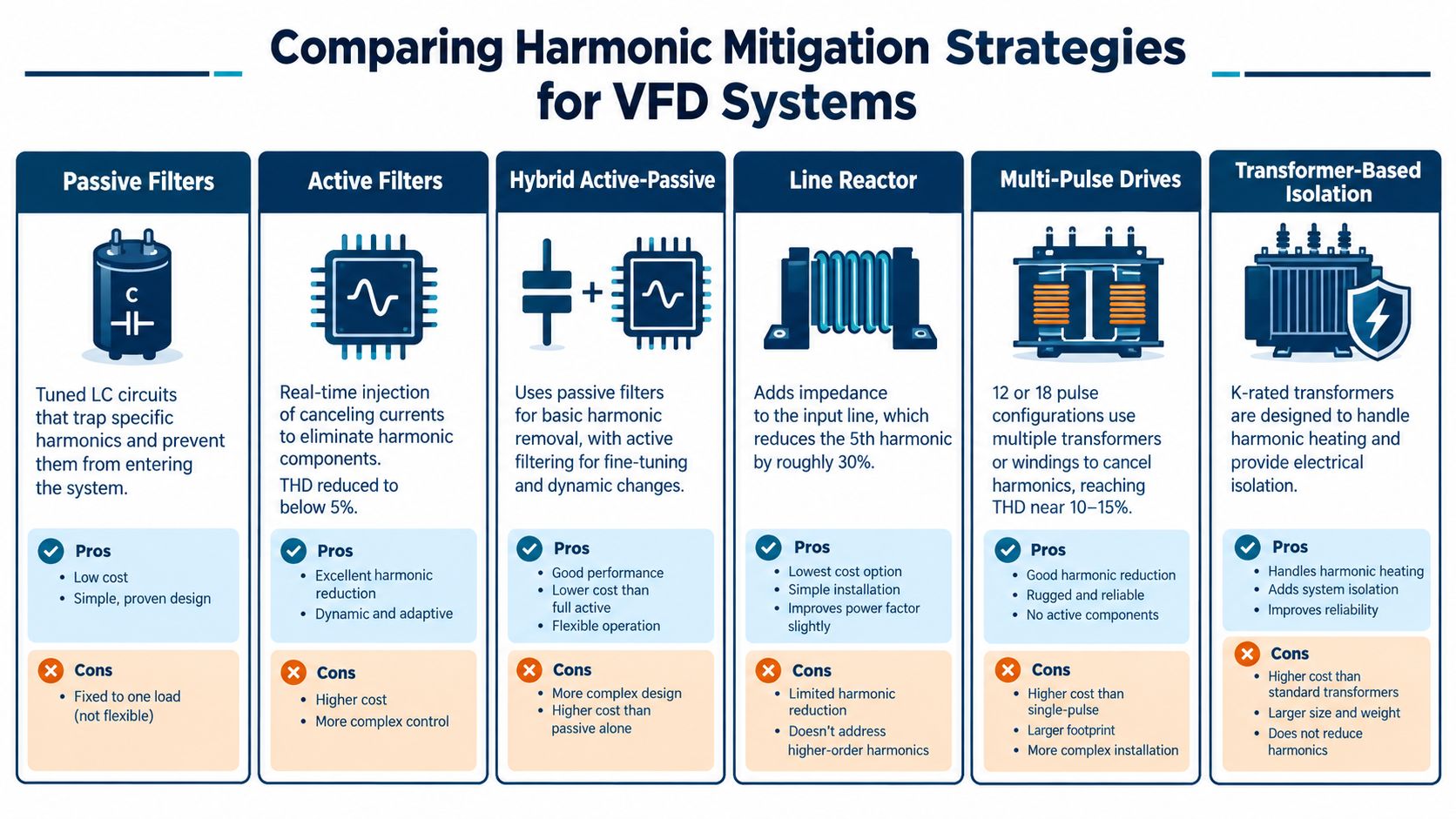
Select mitigation from measured system behavior, not drive nameplate power. A line reactor can suit one drive on a stiff, stable bus. A plant with changing production, several drive groups, or a weak source may need active compensation or a different front-end arrangement. No filter corrects an incorrectly defined PCC, poor wiring, or an overlooked resonance.
Match the method to the system
-
Line reactors add input impedance, reduce current peaks, soften the waveform, and limit some disturbances. They are simple to install, but they do not provide precise correction across every speed and load. Their result depends on source impedance and the equipment sharing the bus.
-
Passive filters use inductive and capacitive components to target selected harmonic orders. They can be economical for a predictable load. Tuning, resonance, fault protection, enclosure space, and future changes to the drive population require review. A fixed filter can become unsuitable when production duty changes.
-
Active filters measure unwanted current and inject a cancelling current. They are suited to changing loads and multiple harmonic components, but require more equipment cost, control coordination, heat removal, and commissioning work. Confirm their response at the operating points that produce the trips, not only at rated load.
-
Hybrid active-passive filters combine fixed reactive support with active correction. Test results can favor one arrangement at full load and another at partial load, so laboratory performance should not be treated as a plant guarantee. The installation and compliance requirements for VFD systems%20Installation%20and%20Compliance%20Requirements%20-%20June%202026%20NTU_508.pdf) reinforce the need to check the source, transformer, generator, UPS, protection, and aggregate load before choosing this approach.
-
Multipulse or phase-shifting arrangements reduce selected characteristic harmonics through phase displacement. They can suit planned installations, but transformers, floor space, coordination, and maintenance access add design obligations.
-
Transformer-based solutions can address isolation, thermal duty, and source interaction. Choose the transformer for the measured harmonic environment. It is not a replacement for system measurements.
Installation decides whether the design survives
Keep power and control wiring separated enough to limit coupling. Verify grounding and bonding against the equipment and site design. Route filter connections as specified, and confirm that protective devices suit the changed fault and current behavior.
Commission the complete arrangement at the PCC under representative operating states. Record current distortion, voltage distortion, loading, and active equipment while the plant is producing normally and while the suspected failure occurs.
The practical test is whether performance holds as drive count, motor speed, source configuration, and capacitor state change. A filter that performs well on a test bench may still leave recurring trips in the installed system.
Why Operating Conditions Make One Filter Inadequate
A filter chosen from nameplate power alone assumes the drive produces a stable harmonic signature. Field measurements challenge that assumption. One reported industrial measurement found current THD rising from approximately 13% to 30% overall, reaching about 45% at low motor frequency, then falling below the applicable limit near fundamental frequency while voltage THD remained below 5%. Those results are specific to the tested installation, but they illustrate why a single snapshot can send a maintenance team in the wrong direction. The industrial measurement study on operating-point effects provides that example.
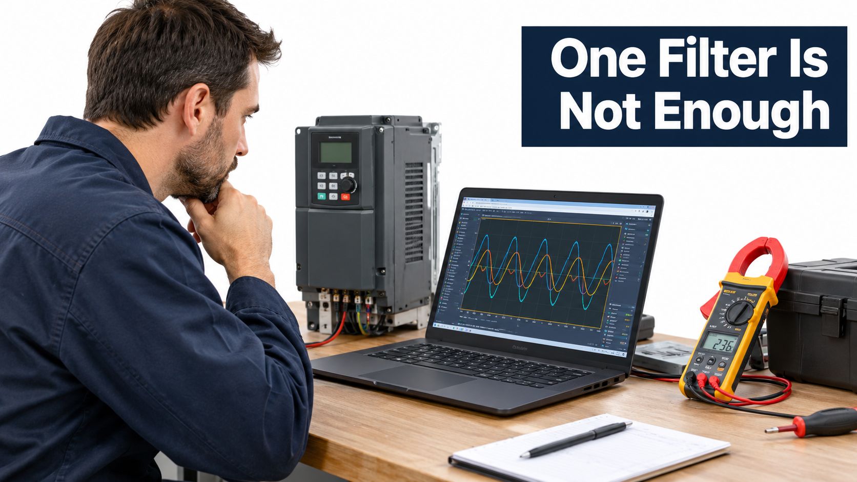
A drive can therefore pass a normal-speed check and still create trouble during low-speed operation, light loading, or a transition. Raw THD can also look high when the fundamental current is small. That's why TDD and PCC voltage quality provide better context for a plant decision than a terminal THD value by itself.
Conditions that expose hidden interactions
A weak source has greater voltage response to injected current than a strong source. Generator operation can alter source impedance and regulation. Capacitor-bank switching can change the network's frequency response, while bypass transitions can move a load between electrical paths. Parallel drives can add their currents at the same PCC even when each individual drive appears acceptable.
These conditions should be captured deliberately:
- Low-speed production: Look for the operating point where current distortion peaks.
- Light load: Compare THD with demand current and avoid judging compliance from THD alone.
- Shared-bus operation: Record which drives and nonlinear loads are active together.
- Source changes: Test utility and generator states when both are part of the operating plan.
- Reactive equipment switching: Correlate capacitor events with trips, heating, or waveform changes.
A filter that works at one operating point is a test result, not yet a reliability solution.
Commissioning should compare the design model with field measurements at the PCC, then preserve the operating conditions beside the results. If the plant replaces a drive, changes a capacitor bank, adds a generator, or expands the drive population, repeat the relevant measurements. The correct response may be a filter, a reactor, a source change, a control adjustment, or no hardware change at all.
<iframe width="100%" style="aspect-ratio: 16 / 9;" src="https://www.youtube.com/embed/-m-5b6jOMSo" frameborder="0" allow="autoplay; encrypted-media" allowfullscreen></iframe>System-Level Diagnostic Workflow for Plant Engineers
A reliable investigation moves from symptom to evidence, then from evidence to controlled verification. It doesn't begin with a filter quotation or a replacement-drive recommendation.
Start with the event, not the component
Pull fault records and maintenance logs for the affected line. Mark when trips, thermal alarms, capacitor failures, control resets, or communication faults occur. Compare those timestamps with production rate, drive speed, bypass status, source changes, and capacitor switching.
Then identify the electrical boundary. Draw the supply path from source to transformer, main switchboard, feeder, PCC, drive group, motor, and control equipment. Include generators, UPS systems, capacitor banks, and other nonlinear loads. A simple one-line diagram often reveals that the suspected drive shares a bus with equipment nobody included in the first diagnosis.
Capture and interpret the evidence
Use a portable analyzer for a temporary survey or a fixed power-quality system when the problem is recurring and operationally expensive. Capture phase voltage, phase current, individual harmonic orders, voltage THD, current THD, demand current, TDD, frequency, power factor, and event timestamps. Check the instrument setup before relying on the result.
Compare the data against the applicable IEEE 519 framework at the PCC. Don't label a drive defective because its terminal current THD is high, and don't declare the plant healthy because a single voltage capture looks acceptable. Review source stiffness, (I_{SC}/I_L), transformer loading, and the combined contribution of nonlinear loads.
Verify the remedy in the same conditions
Select mitigation only after identifying the mechanism. If a reactor is installed, test it under the operating state that created the complaint. If a passive or active filter is installed, verify current and voltage behavior during normal production, low-speed operation, transitions, and source changes that matter to the site.
Record the baseline, the intervention, the final readings, and the exact operating conditions. That documentation gives the next engineer a reference after a drive replacement or shutdown restart. It also prevents the plant from repeating the same investigation whenever a different component fails.
Commissioning record: Save the one-line diagram, PCC definition, analyzer configuration, load state, source state, harmonic spectrum, event log, and acceptance decision together.
Troubleshooting VFD Harmonic Issues in the Field
Field troubleshooting works best when the team tests the most likely system interaction before condemning the drive. A hot transformer isn't proof of a bad transformer. A hot neutral isn't automatically an unbalanced-load problem. A nuisance trip isn't automatically a defective relay.
Use the symptom to choose the first isolation
If transformer or cable temperature rises with the number of operating drives, compare the temperature and harmonic readings as drives are enabled in a controlled sequence. If the change appears only when a capacitor bank is connected, investigate resonance and switching interaction before replacing the VFD.
If the neutral conductor overheats, check phase currents and harmonic sequence behavior. Zero-sequence harmonics can circulate through phase and neutral conductors, producing high neutral current even when the fundamental phase loads appear balanced. If motors show heating, vibration, or abnormal protection response, examine positive- and negative-sequence effects and the voltage waveform at the bus.
A safe isolation plan may include:
- Capture a baseline with the plant in its normal state.
- Remove or change one operating condition under an approved switching procedure.
- Record the PCC response, not only the drive-terminal response.
- Restore the original state and confirm whether the symptom returns.
- Escalate when the result points to resonance, source weakness, or aggregate interaction.
Know when a quick fix isn't enough
A line reactor may reduce a current peak, but it won't resolve every bus-level problem. A passive filter may perform well with a stable load, but its suitability changes when the drive population or capacitor state changes. An active solution may offer flexibility, but it still needs correct sizing, wiring, protection, and verification.
Bring in commissioning or power-quality specialists when the plant has recurring trips after multiple drive replacements, unexplained transformer heating, generator operation, capacitor failures, unexplained neutral current, or sensitive-control interference. The investigation should include the source and all significant nonlinear loads.
After any corrective work, repeat the original test conditions and retain the records. Keep drive parameters, fault logs, one-line drawings, filter settings, reactor details, analyzer files, and commissioning decisions in the asset history. A repair without a comparable post-installation measurement leaves the root cause unproven.
Planning Lifecycle Harmonic Compliance and Maintenance
Harmonic compliance isn't a one-time certificate that stays valid after the plant changes. Drive replacements, production expansions, generator operation, capacitor-bank modifications, and new electronic loads can alter the system response.
Build harmonic checks into preventive maintenance, planned shutdowns, and commissioning handovers. The difference between preventive and corrective maintenance matters here because trend records let a team act before distortion becomes a trip or thermal failure.
Keep a concise checklist:
- During routine maintenance: Review drive fault histories, thermal observations, capacitor events, and changes to the drive population.
- During troubleshooting: Measure at the PCC and affected feeder under the operating condition linked to the symptom.
- During shutdowns: Inspect reactors, filters, wiring, grounding, cooling paths, and recording equipment.
- After changes: Repeat baseline measurements after drive, transformer, generator, capacitor, or filter work.
- For lifecycle support: Store waveforms, spectra, TDD results, source state, load state, and corrective actions with the asset record.
The mindset shift is straightforward. VFD harmonic problems aren't solved by asking which drive is bad or which filter appears on a catalog page. They're solved by measuring how the rectifier, source, other loads, and operating conditions behave together.
DUCHENG Industrial supports VFD commissioning, on-site troubleshooting, preventive maintenance, repair, condition checks, and on-site reconditioning for industrial drive systems. If recurring trips, thermal stress, or unexplained power-quality behavior is affecting your plant, visit DUCHENG Industrial to discuss a measurement-led service plan.